Abstract
To improve the rationality of the mechanical design of traditional ship anchor windlass, based on modal analysis, lightweight research was conducted on key components. Taking the first-order natural frequency as the constraint condition, topological optimization design was carried out for the base, and size optimization design based on the response surface algorithm was carried out for the anchor chain wheel. On the premise of meeting the overall structural strength and stiffness requirements of the anchor windlass, its weight was reduced as much as possible. Through the finite element analysis and strength check of the optimized model, it was verified that the optimization results met the design requirements. The research shows that the weight reduction rate of the base reached 13.34 %, and the weight reduction rate of the anchor sprocket reached 10.5 %. After analysis and verification, the optimized structure can still meet the overall mechanical performance of the anchor windlass and achieve the expected design goal, which also provides an important reference for the structural optimization and lightweight research of other ship equipment.
Highlights
- Taking the first-order natural frequency as the constraint condition, topological optimization design was carried out for the base, and size optimization design based on the response surface algorithm was carried out for the anchor chain wheel.
- On the premise of meeting the overall structural strength and stiffness requirements of the anchor windlass, its weight was reduced as much as possible.
- Through the finite element analysis and strength check of the optimized model, it was verified that the optimization results met the design requirements.
1. Introduction
For marine anchor winch equipment, the modal and strength characteristics are the keys to ensuring the stability and safety of the entire machine [1]. As the traditional design method relies on experience, there may be unreasonable problems. Therefore, it is essential to conduct analysis and optimization based on modal and strength requirements, such as lightweighting [2]. Modal analysis can provide important information about the natural frequency, characteristic mode and amplitude of the structure. These data can help structural engineers optimize the design scheme to ensure the stable operation of the mechanical structure under the most unfavorable working conditions [3, 4]. During the lightweight design research process, many developers still adhere to the traditional concept of weight reduction. Through design, demonstration, prototype experiments, modifications and repeated prototype experiments, and through continuous corrections, qualified products are finally obtained. This lightweight process significantly increases manufacturing costs, causes a large amount of waste of resources, energy, manpower and financial resources, prolongs the product research and development cycle, and limits the further development of marine anchoring equipment [5]. Not only that, the marine anchoring equipment produced through the traditional lightweight design method is too bulky, with a serious phenomenon of material redundancy, an uncompact structure, low mechanical transmission efficiency and large environmental pollution, further leading to an increase in production costs. Under the premise of adhering to the working principle and manufacturing process of the anchor winch, it is very necessary to conduct lightweight research on the key components of the anchor winch by using finite element analysis technology, computer simulation technology and structural optimization technology [6]. Therefore, this paper conducts lightweight design research on material redundancy in the support structure and completes the lightweight research task of key components through proxy models and multi-objective optimization methods, thereby achieving the goals of reducing materials, lowering resource consumption and protecting the environment.
2. Modal analysis of key components
2.1. Analysis of the base part
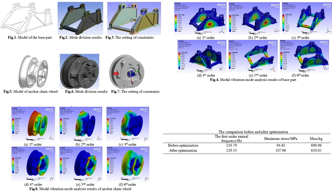
The structure of the anchor machine base is predominantly formed through the welding of several ship plates. In traditional designs, to guarantee its safety, a relatively high safety factor is typically adopted, which leads to the base structure in traditional designs being overly cumbersome and excessively large in volume, thereby resulting in the wastage of materials and energy. Create the solid model of the anchor machine base in SolidWorks. To enhance the quality of the finite element unit mesh division in the subsequent stage and boost the calculation speed and accuracy of the finite element analysis, in accordance with Saint-Venant’s principle, during the modeling process, the anchor machine base model was appropriately streamlined, and structural features such as bolt holes and chamfers that exert minimal influence in the finite element calculation and analysis process were eliminated, as shown in Fig. 1.
Fig. 1Model of the base part
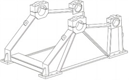
Fig. 2Mesh division results
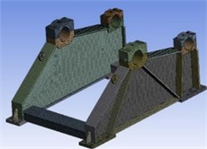
Fig. 3The setting of constraints
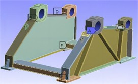
Fig. 4Modal vibration mode analysis results of base part
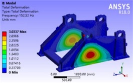
a) 1st order
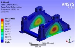
b) 2nd order
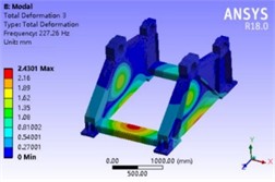
c) 3rd order
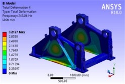
d) 4th order
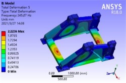
e) 5th order
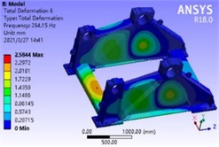
f) 6th order
After importing the three-dimensional model of the anchor machine base into Workbench, the material properties of the base were set first, and then the unit meshing of the base model was carried out. Considering the calculation amount and calculation accuracy of the finite element analysis comprehensively, the size of the mesh unit was set to 30 millimeters, and the free meshing method was adopted. The number of meshed elements was 47,998, and the number of nodes was 154,546, as shown in Fig. 2. The boundary constraint conditions of dynamic analysis mainly include two parts. One part is the same as the boundary constraint conditions of static analysis, setting the fixed constraint of the bolt holes at the bottom of the base. The other part is to set the cylindrical constraint in the bearing housing hole to constrain the radial and axial movements, and only allow the rotation in the circumferential direction, as shown in Fig. 3.
By analyzing the vibration mode shape cloud diagram and natural frequencies of the base, it can be ascertained that the first and second order modal vibration modes respectively represent the outward bulge vibration in the middle of the web plates on both sides of the base and the inward concave vibration of the web plates on both sides of the base. Herein, the protrusion deformation at the lower end of the sprocket bearing seat is the most significant, inducing the web plates on both sides of the base to have an outward separation tendency. The third and sixth order modal vibration modes are the upward bulge vibrations of the front and rear cross beams, resulting in the entire base having an upward tilting tendency. The fourth and fifth order modal vibration modes are the torsional vibrations of the web plates on both sides and the folding vibrations of the front and rear cross beams, causing the entire base to be in a torsional state. Additionally, the lowest natural frequency value of the first order mode is 152.52 Hz, which falls within the safe frequency range. Hence, the first six order vibration modes of the base are all merely local vibration modes, essentially will not resonate with other components, possess favorable dynamic characteristics and fulfill the design requirements.
2.2. Parameterized box body model
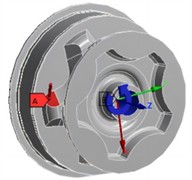
During the anchor raising process of the anchor windlass, the anchor sprocket meshes with the anchor chain and is always in a rotating state. Therefore, the design of the anchor sprocket should not only meet the strength requirements, but also make its vibration mode and natural frequency meet the requirements of its dynamic characteristics to avoid resonance with other shaft components in the working state, which may affect the normal operation of the anchor windlass or lead to other work accidents. Therefore, a prestressed modal analysis of the anchor sprocket is required. The solid model of the anchor chain wheel was imported into ANSYS Workbench, as shown in Fig. 5. In the prestressed modal analysis system, the material properties of the anchor chain wheel, the size of the cells and the division method of the grid cells were defined. The parameter settings were the same as those of the transient analysis, and the finite element mesh model of the anchor chain wheel was obtained as shown in Fig. 6. The external load and boundary conditions of the modal analysis were the same as those of the transient dynamic analysis, that is, a pressure perpendicular to the stressed surface was applied to the meshing surface of the anchor chain wheel and the anchor chain, with a magnitude of 29.18 MPa. At the same time, a cylindrical constraint was set on the inner hole surface of the anchor chain wheel to restrict its radial and axial movements, and only allow its rotation in the circumferential direction, as shown in Fig. 7.
Fig. 5Model of anchor chain wheel
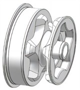
Fig. 6Mesh division results
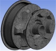
Fig. 7The setting of constraints
From the analysis results of the first six natural frequencies and vibration modes of the anchor sprocket, as shown in Fig. 8, it can be known that the values of the first three natural frequencies of the anchor sprocket are between 130.79 Hz and 157.61 Hz, which are the main vibration modes of the anchor sprocket. The values of the last three natural frequencies are all above 179.20 Hz, which are the local vibration modes of the anchor sprocket. During the anchor hoisting process of the anchor windlass, the anchor sprocket will simultaneously be subjected to the excitations generated by the transmission of the large and small gears and the rotary motion of the sprocket shaft. When the excitation frequency received by the anchor sprocket is consistent with its own natural frequency, resonance phenomenon will occur, generating huge vibrations in a short time, resulting in the inability of the anchor windlass to work normally or causing accidents. Therefore, designers should fully consider the excitation frequencies generated by gear transmission frequencies, meshing frequencies, and bearing vibration frequencies when designing the anchor sprocket. Generally, gear transmission and meshing frequencies are below 100 Hz, and bearing vibration frequencies vary from several tens of Hertz. Therefore, the excitation frequencies generated by the rotation of the sprocket shaft and gear transmission are much lower than the lowest natural frequency value of the anchor sprocket. Therefore, the anchor sprocket will not resonate with other components in the working state, thus meeting the dynamic characteristic requirements.
Fig. 8Modal vibration mode analysis results of anchor chain wheel
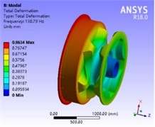
a) 1st order
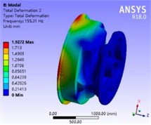
b) 2nd order
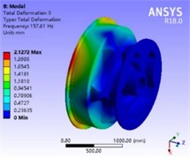
c) 3rd order
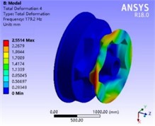
d) 4th order
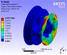
e) 5th order
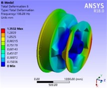
f) 6th order
3. Lightweight of key components
3.1. Topological optimization of the base part
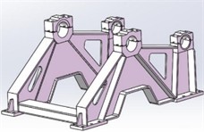
The lightweight design of the base adopts the topological optimization method. Its advantage lies in the combination of the mathematical optimization algorithm with the designer’s own experience. Thus, the correct design scheme can be established at the early stage of the structural optimization design to ensure that the final optimization design result meets the design requirements. The topological optimization process of the base is similar to the finite element analysis. In order to increase the calculation speed and accuracy of the topological optimization, the structural features such as bolt holes and chamfers of the base model are appropriately simplified during the modeling process. During the topological optimization process, on the basis of meeting the corresponding optimization goals, sometimes the optimized structure cannot be completed by the existing process. Therefore, reasonable constraints need to be imposed on the shape of the structure during the optimization process. With the first-order natural frequency as the limiting condition, the model is lightweighted based on Solid Thinking. The shape control and optimization model of the base are shown in Fig. 9.
The comparison results of base part before and after optimization are shown in Table 1. It can be known from the finite element analysis of the optimized model that the total mass of the optimized base model has decreased by 10.64 %, and the first-order natural frequency of the model has basically remained unchanged. Although the maximum stress value of the base after optimization has increased from the original 84.75 MPa to 96.95 MPa, it is still within the allowable stress range of the material and will not have an impact on the reliability of the overall structure of the anchor machine.
Fig. 9Topological optimization model
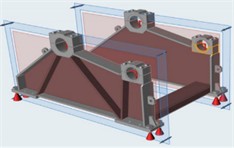
a) Shape control
b) The result after optimization
Table 1The comparison before and after optimization
The first-order natural frequency / Hz | Maximum stress / MPa | Mass / Kg | |
Before optimization | 152.52 | 84.755 | 1372.55 |
After optimization | 150.38 | 96.9 | 1226.88 |
3.2. Response surface optimization of the anchor chain wheel
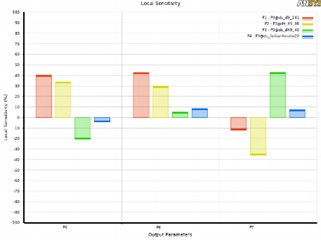
The engagement part between the anchor chain wheel and the anchor chain is the chain ring bearing well, which is composed of the bottom surface of the well and the side surface of the tooth of the wheel. It needs to withstand torque, traction, and impact from all directions, so the internal quality requirements are very strict. In engineering, a relatively large amount of redundant quality is usually used to ensure that the anchor chain wheel has sufficient strength, but it is easy to cause the overall quality to be too large and the local design to be unreasonable. The tolerance meets the requirements of GB/T 1804. In Creo, a parameterized model as shown in Fig. 10 is established, with four categories of design variables, the code number and value range of which are listed in Table 2. The criteria for selecting design variables mainly include two aspects. One is that the main assembly dimensions cannot be changed, and the other is the dimensions that have a significant impact on quality, which can be obtained through sensitivity analysis. The sensitivity of design variables is shown in Fig. 11. It can be seen that the selected design variables all have an important influence on the optimization objective.
Table 2The size variable range of the anchor chain wheel
Name of dimensions | Code | Initial dimensions | Minimum dimensions | Maximum dimensions |
ds_d9_131 | P1 | 131 | 110 | 145 |
ds_d5_38 | P2 | 38 | 30 | 46 |
ds_d49_40 | P3 | 40 | 20 | 80 |
ds_leibanhoudu20 | P4 | 20 | 15 | 25 |
Table 3The comparison before and after optimization
The first-order natural frequency / Hz | Maximum stress / MPa | Mass / Kg | |
Before optimization | 130.79 | 94.63 | 699.96 |
After optimization | 129.33 | 107.96 | 650.05 |
For the optimization of the structure, the minimum value of the mass is taken as the optimization objective, with the boundary conditions of the natural frequency not being lower than the initial value and the stress peak not being higher than the initial value. The polynomial fitting method is used to obtain the response surface function, and the Sequential Quadratic Programming algorithm can be used to obtain the optimal solution that satisfies the boundary conditions. The size optimization of the anchor chain wheel was carried out by using the Design Explorer optimization design module of ANSYS Workbench software with the multi-objective genetic algorithm. The comparison results of anchor chain wheel before and after optimization are shown in Table 3. It can be known from the finite element analysis of the optimized model that the total mass of the optimized anchor chain wheel has decreased by 7.1 %, and the first-order natural frequency of the model has basically remained unchanged. Although the maximum stress value of the base after optimization has increased from the original 94.63 MPa to 107.96 MPa, it is still within the allowable stress range of the material and will not have an impact on the reliability of the overall structure of the anchor machine. Due to the fact that the optimized structure did not change the overall structural layout and symmetry, only minor adjustments were made to local dimensions. Therefore, compared to the impact on natural frequency and mass, the modal shapes hardly changed.
Fig. 10Parametric model
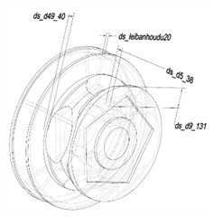
Fig. 11The sensitivity of design variables
4. Conclusions
1) Through multi-objective optimization method, it is possible to effectively improve structural configuration, reduce weight, and achieve good cost-effectiveness without compromising the mechanical performance and dynamic response. Through lightweight design, the total mass of the optimized base model and anchor chain wheel can be reduced by 10.64 % and 7.1 %. Optimization analysis not only meets the requirements of static strength, but also conforms to the dynamic characteristics, thereby reducing the probability of abnormal operation or other work accidents of the anchor device.
2) The total mass of the optimized basic model is significantly reduced, but the first-order natural frequency remains basically unchanged, and the economic effect is obvious. Although the maximum stress value of the optimized base has increased to a certain extent, it is still within the allowable stress range of the material and will not affect the reliability of the overall structure of the anchor machine.
References
-
M. R. Zarastvand, M. H. Asadijafari, and R. Talebitooti, “Acoustic wave transmission characteristics of stiffened composite shell systems with double curvature,” Composite Structures, Vol. 292, No. 1, p. 115688, Jul. 2022, https://doi.org/10.1016/j.compstruct.2022.115688
-
R. Talebitooti, M. Zarastvand, and H. Darvishgohari, “Multi-objective optimization approach on diffuse sound transmission through poroelastic composite sandwich structure,” Journal of Sandwich Structures and Materials, Vol. 23, No. 4, pp. 1221–1252, Jun. 2019, https://doi.org/10.1177/1099636219854748
-
R. Talebitooti, H. D. Gohari, and M. R. Zarastvand, “Multi objective optimization of sound transmission across laminated composite cylindrical shell lined with porous core investigating Non-dominated Sorting Genetic Algorithm,” Aerospace Science and Technology, Vol. 69, No. 1, pp. 269–280, Oct. 2017, https://doi.org/10.1016/j.ast.2017.06.008
-
H. D. Chalak, A. M. Zenkour, and A. Garg, “Free vibration and modal stress analysis of FG-CNTRC beams under hygrothermal conditions using zigzag theory,” Mechanics Based Design of Structures and Machines, Vol. 51, No. 8, pp. 4709–4730, Aug. 2023, https://doi.org/10.1080/15397734.2021.1977659
-
R. K. Bhamu, “Vibration response of steam turbine healthy and cracked blade under the stress stiffening and spin softening effects,” Proceedings of the Institution of Mechanical Engineers, Part K: Journal of Multi-body Dynamics, Vol. 236, No. 2, pp. 224–243, Feb. 2022.
-
I. Aarab, K. E. Amari, A. Yaacoubi, A. Etahiri, and A. Baçaoui, “Optimization of the flotation of low-grade phosphate ore using DOE: a comparative evaluation of fatty acid formulation to sodium oleate,” Mining, Metallurgy and Exploration, Vol. 40, No. 1, pp. 95–108, Dec. 2022, https://doi.org/10.1007/s42461-022-00706-w
About this article
The authors have not disclosed any funding.
The datasets generated during and/or analyzed during the current study are available from the corresponding author on reasonable request.
The authors declare that they have no conflict of interest.
