Abstract
In order to effectively achieve the optimization design of the aircraft cargo rack, based on finite element modal simulation, the structure was redesigned and analyzed using two schemes of surrogate model size optimization and topology optimization, ensuring the strength requirements while improving the natural frequency and reducing the weight. According to the modal shape of vibration, additional bridge structures were added at the weak points to improve the dynamic stiffness of the structure. According to the optimization design requirements, the response surface function was constructed, and the particle swarm optimization algorithm was applied in the size optimization and surrogate model solution. A multi-objective optimization model was established for flexibility and low-order natural frequencies, and topology optimization was carried out in HyperWorks. The structural dynamic modification of the topology optimization model was performed using the modal strain energy analysis method. The research results show that both optimization methods can achieve good lightweight design. The static performance of the optimized structure is stable, and the overall modal frequency is improved.
Highlights
- According to the modal shape of vibration, additional bridge structures were added at the weak points to improve the dynamic stiffness of the structure.
- According to the optimization design requirements, the response surface function was constructed, and the particle swarm optimization algorithm was applied in the size optimization and surrogate model solution.
- A multi-objective optimization model was established for flexibility and low-order natural frequencies, and topology optimization was carried out in HyperWorks.
1. Introduction
Compared to conventional cargo racks, the strength and stability requirements for airplane cargo racks are more stringent, necessitating modal analysis of mechanical structures. Modal analysis primarily entails investigating the dynamic characteristics of the airplane shelf structure and comprehending its response to external excitation by analyzing its vibration characteristics across various frequencies. This aids in assessing the dynamic performance and reliability of the shelf model. Modal analysis constitutes a crucial aspect of structural dynamics, enabling engineers to anticipate and mitigate resonance phenomena during the design phase, thereby ensuring that the airplane shelf can securely and dependably accommodate cargo during transportation, storage, and utilization. For the design of cargo rack, the traditional design method is based on empirical design and static design, and the design process mainly relies on formulas, experience, and reference manuals for semi-theoretical and semi-experiential design. The traditional design method requires multiple trial-and-error design in the design of new products, and formal design can only be carried out after the designer has accumulated mature design experience. This design method that is dominated by experience is difficult to effectively control the specific design process, and its accuracy and reliability depend on the designer's own level. It is difficult to quantify. In addition, the traditional design method often pays too much attention to the product itself in the design process, while neglecting the quality, cost, and service-related content throughout the product's entire life cycle. Where mechanical equipment functions are becoming more diverse and operation is becoming smarter, the traditional design method is no longer able to meet the needs of market development. In response to the above problems, this paper proposes a structural optimization method based on modal analysis. On the basis of the topology optimization model, modal strain energy is introduced to accurately identify weak points and perform dynamic modifications, thereby achieving lightweight design and optimization of the rack structure while ensuring its static and dynamic performance.
2. Modal and strength analysis
2.1. The establishment of finite element model
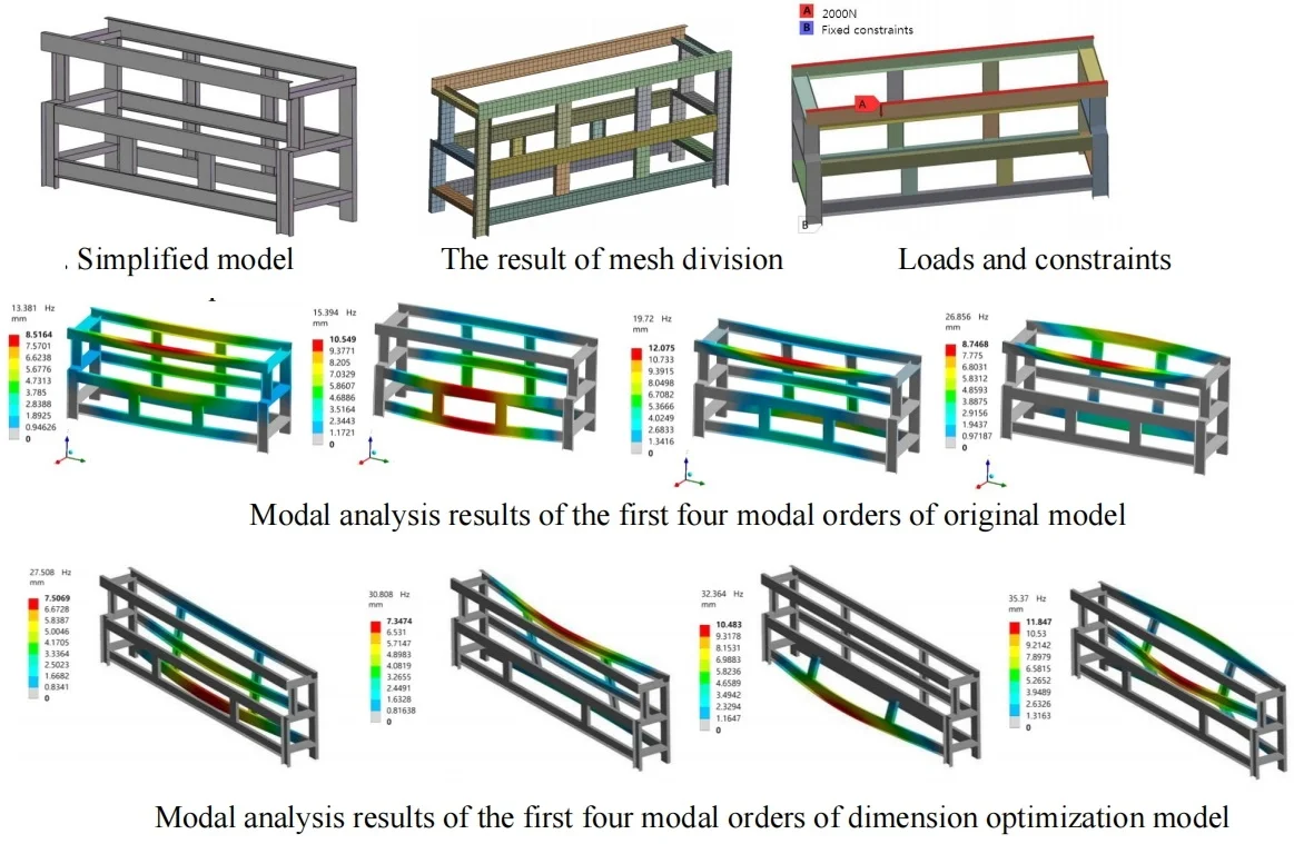
A finite element model, established using the finite element analysis method, constitutes a pivotal element of the entire finite element analysis process. The precision of subsequent computational outcomes, computation duration, and smoothness of the calculation process are directly impacted by the quality of the finite element model. The structural configuration of the rack model is illustrated in Fig. 1. The initial weight of the model is 180.58 kg. To ensure efficient mesh division in subsequent stages and reduce solution complexity, a simplified approach was employed during its establishment, disregarding features such as rounded corners on the channel steel. In the mesh division, since the rack structure is a regular solid structure, the hexahedral element is used for division. The size of the model unit is set to 40 mm based on the geometric dimensions of the structure, resulting in 25266 nodes and 3030 elements, as shown in Fig. 2. According to the load size of each device, the part with the largest load is selected for strength analysis. The model is imported into ANSYS Workbench for stress analysis. In the actual working environment, the model is fixed to the ground, so the 6 degrees of freedom of the four support points of the host frame are constrained during the analysis. Therefore, a load of 2000 N is applied at the top of the channel steel as shown in Fig. 3.
Fig. 1Simplified model
Fig. 2The result of mesh division
Fig. 3Loads and constraints
2.2. Results analysis and discussion
After completing the boundary constraints and load setting, the static structural simulation analysis was solved. The stiffness and strength of the model were analyzed by the total deformation and maximum equivalent stress, as shown in Fig. 4. From the deformation results, it can be seen that the total deformation of the model under an external load of 2000 N is about 1.26 mm, and the main deformation is twisting along the X direction. The total deformation is negligible compared to the overall size, indicating good stiffness. In the subsequent optimization design process, this will be used as a constraint condition for optimization, i.e., the subsequent optimized deformation should not exceed this value.
Fig. 4Results of strength analysis
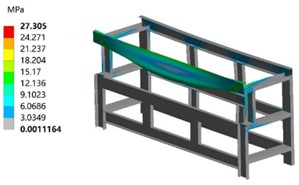
a) Results of stress
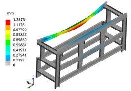
b) Results of displacement
According to the stress cloud map, it can be seen that the position of the maximum equivalent stress and the maximum deformation are the same, both located at the beam subjected to the load, and the maximum equivalent stress value is 27.31 MPa. The safety factor is high, and there is a large optimization margin. The stress distribution is symmetrical. The allowable stress of the model is 117.5 MPa. The maximum equivalent stress value received is much smaller than the allowable stress of the material, and it will be used as the optimization constraint condition in subsequent optimization. The modal analysis results of the first four modal orders are shown in Fig. 5. From the mode shape cloud diagram, it can be seen that the first and second modal shapes mainly consist of bending in the X-Y plane of the main frame in the middle, while the third and fourth modal shapes undergo torsion along the Y axis. The maximum deformation occurs at the 1/2 position of the upper beam, where the deformation changes the relative positions of the structures and affects the model stiffness, making this location more important for the entire model.
Fig. 5Modal analysis results of the first four modal orders of original model

3. Optimization of mechanical structures
3.1. Agent models and dimension optimization
Agent models refer to the use of statistical and experimental design methods in data analysis and optimization design to establish a functional relationship between design variables and responses. This functional relationship is used to replace the approximate mathematical model, which is more complex and time-consuming, thus also known as an approximation model or meta-model. Common agent models include polynomial response surface models, radial basis function models, and Kriging models, among others. The establishment of higher precision polynomial response surface models relies heavily on the sampling technology for the design space. Experimental design involves selecting representative points from a large number of trial points using mathematical statistics and orthogonal principles, and arranging the trial design rationally with the help of an orthogonal table. Latin hypercube sampling is a commonly used experimental design method for studying the distribution of multi-parameters, enabling uniform data sampling from the design space and reflecting the characteristics of the entire design space.
According to the principle of optimization design, it can be known that before fitting the response surface function, discrete data samples need to be obtained. Through the Latin hypercube sampling method, the dimension combinations of different design variables, including length and width, can be reasonably allocated, as shown in Fig. 6. Under these combinations of design variables, the corresponding mass and the first-order natural frequency can be calculated, which can be used as the basis for constructing the approximate model. After measuring the performance of each device, the total length of the model is required to be between 7000-7500 mm, and the width is required to be between 800-1,300 mm, and the two-stage structure is still adopted. Using the Latin hypercube sampling method to sample the length and width, a total of 150 sample data sets are obtained, and 125 of the sample data sets are set as training set samples, while the remaining 25 are set as test set samples.
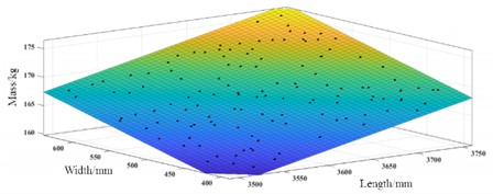
The quadratic polynomial response surface model for fitting quality and dimensions is shown in Fig. 7. The coefficient of determination of the test set is 0.9996, and the root mean square error is 0.005, indicating that the quadratic polynomial response surface model fits well and can be used to represent the theoretical model for subsequent optimization. The size optimization design takes length and width as design variables, and the quadratic polynomial established about quality as the objective function, with the interval of length and width as the constraint conditions. The particle swarm optimization algorithm is used to optimize the objective function, and the length and width that minimize the quality are obtained, achieving the goal of lightweighting. In the dimensionally optimized boundary conditions, set the first-order natural frequency of the model to be no less than the initial value of 13.84 Hz.
Fig. 6Combination of dimensional sampling
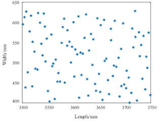
Fig. 7Response surface function
The optimized model weight is 159.349 kg, with a weight reduction rate of 11.7 %. Conducting modal analysis on the model with constraints on modal frequencies, the first four modal frequencies and displacement contour maps of the optimized model can be shown in Fig. 8. It can be seen that the natural frequencies have been significantly increased under the condition of weight reduction. The deformation of the rack mainly occurs at the beam section, where it shows a bending movement along the X-axis in the front and back directions. Among them, the bending deformation of the two upper beams is relatively large. If specific reinforcement measures are taken, they can be installed at this location, which is the key area for optimization.
Fig. 8Modal analysis results of the first four modal orders of dimension optimization model

3.2. Topology optimization
Topology optimization is a conceptual design method that primarily provides designers with certain material distribution schemes. After topology optimization, the specific shape and size of the structure still need to be redesigned based on the optimization results. Based on modal characteristics, the variable density method is used, whose basic idea is to assume that the structure is composed of several units, and the material density of these units can vary within the range of [0, 1]. The material interpolation model is used to link the material properties with the unit density, and a certain linear or nonlinear relationship is established. Using the variable density method can transform the discrete variable topology optimization problem into a more solvable continuous variable topology optimization problem. However, applying the variable density method generates a large number of intermediate density elements, which have no actual manufacturing significance in practical engineering, so to eliminate the intermediate density, a material penalty model is proposed to make the intermediate density approach 0 or 1, thereby enhancing the structural manufacturability. The penalty function curve is shown in Fig. 9, where the element elastic modulus of the material is determined by the material penalty function, and the unit elastic modulus is approached towards 0 or 1 by adjusting the size of the penalty factor. In the process of modifying the structural dynamics, the first step is to determine the weak points of the structure, and then modify the weak points according to the conditions to achieve the design goal of making the mechanical dynamic characteristics meet the requirements. Strain energy is stored in the form of strain and stress as potential energy in an object, and the modal strain energy distribution reflects the region of deformation in the structure's modal shape at that mode, the greater the deformation, the greater the strain energy in the structure, the lower the stiffness, therefore, the weak points of the structure can be determined more accurately by modal strain energy. According to the results of iterative optimization, the maximum flexibility value before optimization was 1.125 m/N. Through iterative optimization, the flexibility value was continuously reduced, and the final result was 0.743 m/N. Using OptiStruct for single-objective flexibility topology optimization, retaining elements with a density threshold of 0.7 or above, the topology optimization process is shown in Fig. 10, which shows that some elements with a relative density of 0 in the original model were removed, but some I-beams were retained, which do not have practical value and need to be completely removed in subsequent optimization. In structural optimization, increasing the lower-order natural frequencies can improve modal characteristics. When optimizing structures, to avoid the frequency oscillation phenomenon caused by the increase of the first-order frequency while other order frequencies decrease, the mathematical model of the natural frequency topology optimization is defined by the average eigenvalue.
Fig. 9The change trend of penalty function
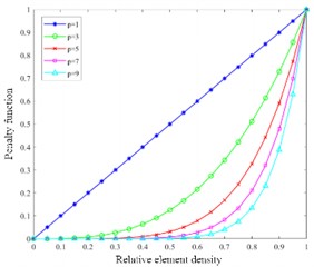
Fig. 10The process of topology optimization
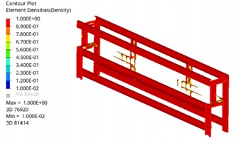
Fig. 11Topology optimization result
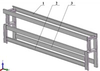
Fig. 12Topology optimization result
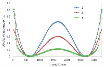
Fig. 13The results of stress
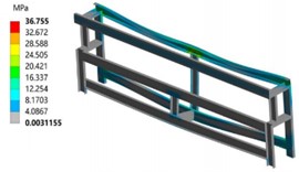
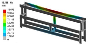
Fig. 14The results of 1st modal shape
According to the optimized results of the material density distribution cloud map, the topology optimized structure has a complex shape, large and irregular holes, and needs further processing on the used I-beams. After considering the manufacturing cost and processing difficulty, modifications are made to the original model based on the topology model, retaining the main structure. The modified topology model is shown in Fig. 11. As shown in Fig. 12, the larger the modal strain energy of a unit, the lower the stiffness of the structure at that location and the easier it is to deform. According to the modal strain energy curve, the peak values of the modal strain energy of each beam are all located at the ends and the middle position. The ends of the beams are the connection parts, where each beam intersects and connects with the others. Therefore, it is necessary to connect each beam firmly and reliably. The stiffness at the middle position is insufficient, and it is easier to deform compared to other positions when subjected to external excitation. Therefore, a bridge structure is added at the middle position of each beam to complete the second structural optimization.
The topology optimization results show that the mass can be reduced by 9.8 % compared to the initial model, which is not much different from the size optimization. Through finite element analysis, it can be known that the maximum stress of the optimized model is 36.75 MPa, the first-order natural frequency is 16.54 Hz, both of which meet the working requirements.
4. Conclusions
Using the particle swarm optimization algorithm to optimize the geometric parameters under the constraint conditions, the optimal dimensional parameters that minimize the mass can be obtained, with a mass reduction of 11.9 %. Topology optimization is performed in HyperWorks, and the topology optimization model can be obtained. The topology optimization model is modified structurally using the modal strain energy analysis method by adding bridge structures in the weak areas to improve the structural dynamic stiffness. The mass of the topology optimization model is reduced by 9.8 %, the static performance is stable, the overall modal frequency is improved, and the lightweight design requirements are achieved. Both optimization schemes can achieve performance improvement and cost reduction, which has important guidance for the advanced design of products.
References
-
Y. Wang, “Lightweight steering equipment based on prestressed modal analysis,” Journal of Vibroengineering, Vol. 26, No. 2, pp. 370–382, Mar. 2024, https://doi.org/10.21595/jve.2023.23547
-
P. Purwanto, N. F. Qaidahiyani, M. S. Ikbal, and D. Djamaluddin, “Shear strength analysis of rock due to the effect of surface roughness based on laboratory testing and numerical modeling,” Materials Science Forum, Vol. 1091, No. 1, pp. 81–92, Jun. 2023, https://doi.org/10.4028/p-q863a9
-
I. Aarab, K. E. Amari, A. Yaacoubi, A. Etahiri, and A. Baçaoui, “Optimization of the flotation of low-grade phosphate ore using doe: a comparative evaluation of fatty acid formulation to sodium oleate,” Mining, Metallurgy and Exploration, Vol. 40, No. 1, pp. 95–108, Dec. 2022, https://doi.org/10.1007/s42461-022-00706-w
-
S. Michałek et al., “The design of experiments (DoE) in optimization of an aerobic flow Pd-catalyzed oxidation of alcohol towards an important aldehyde precursor in the synthesis of phosphatidylinositide 3-kinase inhibitor (CPL302415),” RSC Advances, Vol. 12, No. 52, pp. 33605–33611, Nov. 2022, https://doi.org/10.1039/d2ra07003k
-
K. J. Kim, “Light-weight design and fatigue characteristics of automotive knuckle by using finite element analysis,” Journal of Mechanical Science and Technology, Vol. 35, No. 7, pp. 2989–2995, Jun. 2021, https://doi.org/10.1007/s12206-021-0622-0
-
B. A. Nitalikar, D. R. Kulkarni, and Z. A. Patel, “Structural and finite element analysis of steering yoke of an automobile,” International Journal of Engineering and Management Research, Vol. 10, No. 5, pp. 168–175, May 2020, https://doi.org/10.1007/10.31033/ijemr.10.5.13
-
R. Talebitooti, M. Zarastvand, and H. Darvishgohari, “Multi-objective optimization approach on diffuse sound transmission through poroelastic composite sandwich structure,” Journal of Sandwich Structures and Materials, Vol. 23, No. 4, pp. 1221–1252, Jun. 2019, https://doi.org/10.1177/1099636219854748
About this article
The authors have not disclosed any funding.
The datasets generated during and/or analyzed during the current study are available from the corresponding author on reasonable request.
The authors declare that they have no conflict of interest.

