Abstract
The modal characteristics of the crusher rotor and shell constitute the crucial factors influencing vibration and noise. Based on the principle of simplification, the rotor component model was established. Through mesh optimization, the model accuracy and calculation efficiency can be ensured, and the calculation of natural frequency and modal shapes was completed based on ANSYS. To verify the accuracy of the finite element model, the modal test was carried out by the hammering method. Sensors were set in three different directions to obtain the frequency response function and the modal assurance criterion matrix mode confidence criterion. Using the same research method, the modal characteristics of the shell model were simulated and analyzed. The research results show that the modal parameters identified by the modal test are basically consistent with the simulation model. The natural frequencies of the rotor and the shell are quite different from the excitation frequency of the motor, and resonance problems will not occur when the crusher is proper functioning.
1. Introduction
Modal analysis is an important method for studying the dynamic characteristics of structures and is crucial for crushers with large loads [1, 2]. Modal analysis can mainly be divided into two methods: computational modal analysis and experimental modal analysis. With the development of computer technology, modal analysis conducted through digital simulation technology is becoming increasingly popular, providing better conditions for achieving computational modal analysis [3, 4]. The rotor and the housing are the parts that are most significantly affected by vibration responses. Through modal analysis, the natural frequencies and modal shapes of the rotor and the housing can be understood, and then the responses of each part under different excitations can be predicted to assess whether resonance or instability is likely to occur, which is essential for ensuring the safety and stability of the system [5, 6]. Modal analysis helps determine the modal parameters of key components, and this information is very important for designing effective vibration reduction strategies (such as reducing the vibration amplitude, improving operational stability, and extending the service life of the transmission mechanism). To ensure the accuracy of the modal calculation, a vibration test system of the crusher was constructed in this paper, and free modal tests were carried out on it. The collected signals were analyzed and processed to obtain its vibration characteristics. The natural frequencies of the crusher rotor and the housing were obtained through modal tests. If there is a deviation, the finite element model can be corrected based on the modal parameters obtained in the experimental modal analysis.
2. Modal analysis of the rotor structure
2.1. Establishment and simplification of the rotor model
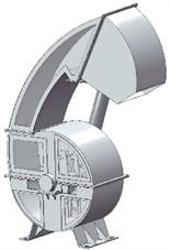
The rotor structure of the crusher is shown in Fig. 1(a). It is a complex structure that not only includes main components such as the main shaft, hammer pieces, connecting plates, hammer pieces, pin shaft sleeves, round nuts, shaft sleeves and support plates, but also has many small structures, such as bolts and nuts. To avoid having too small elements during the finite element meshing process and generating singularities when generating the element stiffness matrix, which would lead to increased analysis result errors and inaccurate analysis, the local features of the rotor group are simplified. Local features such as chamfers and keyways on the shaft are simplified during the modeling process, thereby avoiding calculation inaccuracies caused by mesh unit problems during meshing. There are many small parts in the rotor group, and they have little influence on the subsequent analysis results, so they are not considered. Because the simplified structure does not bear and transmit loads, and the model’s mass remains essentially unchanged, the effect of structural simplification on the accuracy of modal analysis results can be ignored. The established three-dimensional simplified model is shown in Fig. 1(b).
Fig. 1Establishment of the rotor model
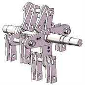
a) Initial model
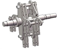
b) Simplified model
2.2. The preprocessing of the model
Based on the modal module of ANSYS, the finite element analysis and calculation of the crusher rotor were carried out. The material of the finite element mode was set as structural steel, and the mm unit system was adopted. The three-dimensional solid model of the rotor established in SolidWorks was imported into the geometry module of Workbench in the x_t format. The finite element meshing of the rotor was performed using the meshing tool provided by ANSYS. The accuracy of meshing is related to factors such as the type of mesh element, the size of mesh element, and the quality of meshing. Generally speaking, the higher the order of interpolation of mesh element nodes, the smaller the element size, the better the element division quality, and the higher the accuracy of the mesh. After many attempts, to minimize the calculation errors caused by mesh quality and mesh quantity as much as possible, the global mesh base size was finally determined to be 3 mm. According to the different structures, mixed meshing was adopted, and finally 123,500 meshes and 603,941 nodes were established, as shown in Fig. 2(a). Taking the element quality as the mesh metric standard, the worst mesh quality of the established finite element model of the rotor was 0.30, the maximum quality was 1, and the average quality was 0.859. The distribution of the number of meshes under different qualities is shown in Fig. 2(b).
Fig. 2Mesh generation results
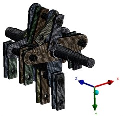
a) The division of the mesh
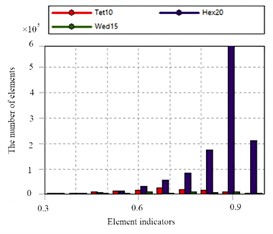
b) The inspection of mesh quality
2.3. Discussion of modal results
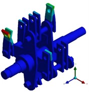
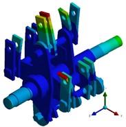
Theoretically, the first six modal frequencies of the unconstrained free mode are equal to 0, presenting as the translation and rotation of the rotor along the , , and axes. In the actual engineering analysis, it is found that the lower the modal order is, the larger the modal effective mass is, and the easier it is to be excited by the external environment. Therefore, in the finite element calculation mode, the seventh mode is actually the first elastic mode. The calculation results of the first six non-zero free modal frequencies of the rotor are extracted and shown in Table 1. Modal shapes of rotor structure are shown in Fig. 3. The first-order vibration mode of the crusher rotor is characterized by the bending of a single set of integral hammer blades on the same side in the plane. The maximum deformation position occurs at the edge line of the outermost hammer blade at the end of the hammer blade set, and the maximum deformation amount is 77.674 mm. The second-order vibration mode is represented by the bending of a single set of local hammer blades on the same side in the plane. The maximum deformation position appears at the edge line of the outermost hammer blade at the end of the hammer blade set, and the maximum deformation amount is 89.076 mm. The third-order vibration mode shows the symmetrical bending between adjacent hammer blades of the hammer blade set on the same pin shaft, and the deformation at the edge of the hammer blade is the largest, with the maximum deformation amount being 114.5 mm. The fourth-order vibration mode is characterized by the symmetrical bending between local adjacent hammer blades of the hammer blade set on the same pin shaft, and the deformation at the edge of the hammer blade is the largest. The fifth-order vibration mode is represented by the torsion of the rotor as a whole in the plane and the bending of the integral hammer blades in the plane. The initial deformation position occurs in the deformation at the end of the hammer blade, and the maximum deformation amount is 54.237 mm. The sixth-order vibration mode is composed of the bending of both ends of the rotor in the plane and the bending of the hammer blades in the and planes. The maximum deformation position occurs at the edge line of the inner hammer blade at the end of the hammer blade set, and the maximum deformation amount is 51.982 mm. In the actual rotor vibration forms, combinations of bending and torsion are mostly present, and single vibration forms are relatively rare.
Table 1The first six natural frequencies
Order | 1 | 2 | 3 | 4 | 5 | 6 |
Nature frequency / Hz | 569.36 | 588.68 | 619.15 | 6955.33 | 722.64 | 747.37 |
Fig. 3Modal shapes of rotor structure
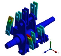
a) The first order
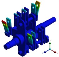
b) The second order
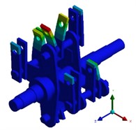
c) The third order
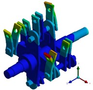
d) The fourth order
e) The fifth order
f) The sixth order
2.4. Verification of modal experiments
During the test, a rubber rope was used to suspend the rotor on the test frame, keeping it in a free suspension state. The measured suspension frequency of this structure was less than 10 % of the first natural frequency of the structure, which was a reasonable support. Since a single-axis acceleration sensor was used in this experiment, the hammering test was conducted three times, namely in the direction, direction, and direction. The acceleration sensors were respectively arranged at the hammer frame plate and the connecting plate, as shown in Fig. 4. Since the signals output by the acceleration sensor and the excitation force hammer were both electrical charges while the input signal of the data acquisition card was a voltage analog quantity, a charge amplifier was required for the conversion between electrical charge and voltage. Based on the upper and lower limits of the input voltage of the data acquisition card, the sensitivity and range of the acceleration sensor and the excitation force hammer, the amplification or reduction multiple of the charge could be calculated. The sampling frequency was set at 5000, the acquisition time was 1 second, the trigger and superposition times at each measurement point were 5 times. The calculation of adding windows to the transfer function was processed by adding a Hanning window. After setting the relevant parameters, the test was conducted. The three frequency response functions of the hammer mill rotor obtained by hitting the measurement points are shown in Fig. 5.
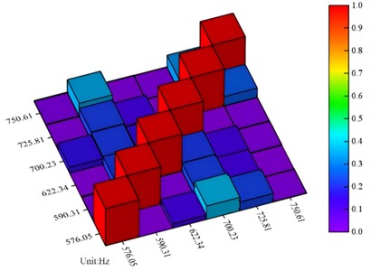
Through the correlation analysis of the crusher rotor mode, the MAC (Modal Assurance Criterion) matrix mode confidence criterion was obtained, as shown in Fig. 6. The MAC value at the main diagonal of the matrix is equal to 1, while the values outside the main diagonal are much less than 1. The MAC value of the same mode is 1, indicating that the theoretical modes are correlated; for the smaller values outside the non-diagonal of the matrix, it indicates that the independence of each order of calculated modes is better and the correlation is smaller, indicating that the mode test effectively extracts the modal parameters of the structure, and the test results have high credibility.
Fig. 4Modal testing scheme

Fig. 5Frequency response function
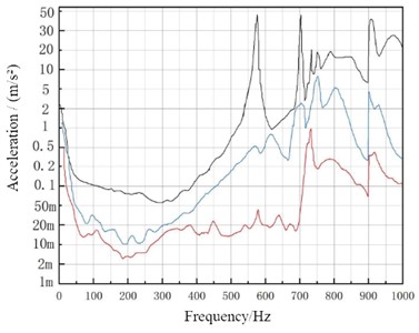
Fig. 6The MAC matrix mode confidence criterion
3. Modal analysis of shell structure
3.1. The establishment of the finite element model
The solid model of the crusher shell established in SolidWorks was imported into the geometry module in Workbench in the x_t format, and the finite element meshing was carried out on it using the meshing tool provided by ANSYS. Considering the computing resources and computing accuracy comprehensively, the global mesh base size was finally determined to be 5 mm, and the mixed meshing was adopted to finally establish the finite element model. Taking the element quality as the mesh metric standard, the number of elements of the finite element model established this time was 817,764, and the number of nodes was 603,941, as shown in Fig. 7. Taking the element quality as the grid evaluation index, the worst quality of the finite element mesh model established this time was 0.17, the maximum quality was 1, and the average quality was 0.789.
Fig. 7Optimization scheme
a) Three-dimensional model
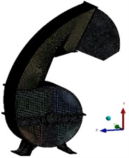
b) The mesh model
3.2. Discussion of modal results
The unconstrained free modal calculation is conducted for the crusher shell, so the influence of damping does not need to be considered. The modal of the crusher shell is only related to its own mass and stiffness. Apart from setting the contact between the acrylic plate and the crusher as a non-separating binding constraint, no other constraint conditions need to be set. For the shell structure, the effective participation factors of the low-order modes are larger. Compared with the rotor parts, the difference between the shell and the working excitation frequency of the motor is also greater. The effective natural frequencies of the first three orders are extracted as shown in Table 2, and the corresponding modal shape results are shown in Fig. 8. Since the validity verification of the model has been completed through the modal analysis of the rotor, therefore, the repeated verification is no longer necessary for the modal analysis of the shell under the same research method.
Table 2The first three natural frequencies
Order | 1 | 2 | 3 |
Nature frequency / Hz | 569.36 | 588.68 | 619.15 |
It can be seen from the analysis results of the vibration mode that the vibration displacement of the shell is mainly distributed at the discharge port and the separation device, and the vibration forms are mainly local bending and torsion. The first-order vibration mode is mostly manifested as the overall bending and torsion of the discharge component. The second-order vibration mode is mainly the torsional deformation vibration on the side of the discharge port. The third-order vibration is mainly based on the deformation of the separation chamber. With the increase of frequency, the influence on the discharge port becomes smaller and smaller.
Fig. 8Modal shapes of shell structure
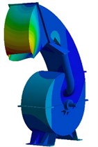
a) The first order
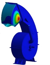
b) The second order
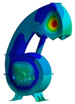
c) The third order
4. Conclusions
1) The vibration of the crusher is a forced vibration caused by a simple harmonic force. The alternating load brought to the bearing seat by the eccentric rotation of the rotor causes the excitation displacement of the base and the shell. Through finite element calculation, it can be concluded that the main vibration mode of the rotor is mainly the bending-torsion combination of the hammer group, and the maximum deformation occurs at the end of the hammer. According to the critical speed of the rotor, there is no possibility of resonance.
2) In terms of the verification of the finite element simulation, the hammering method was adopted to conduct the free modal test on the rotor. According to the test results of the natural frequency, it can be known that the accuracy of this finite element simulation model is relatively high and no correction is required. This also proves that the digital simulation technology has good reliability in modal analysis and can provide an important basis for engineering research and development.
References
-
Y. Wang, “Mesh refinement of finite element method for free vibration analysis of variable geometrical rotating cylindrical shells,” Engineering Computations, Vol. 40, No. 1, pp. 210–228, Jan. 2023, https://doi.org/10.1108/ec-02-2022-0082
-
H. Tomobe, V. Sharma, H. Kimura, and H. Morikawa, “An energy-based overset finite element method for pseudo-static structural analysis,” Journal of Scientific Computing, Vol. 94, No. 3, pp. 203–219, Jan. 2023, https://doi.org/10.1007/s10915-023-02113-9
-
A. Ajay Didolkar, S. Aniket Dhavale, and B. Kothavale, “Structural acoustics analysis of automobile parts by using finite element method,” Materials Today: Proceedings, Vol. 72, No. 3, pp. 1297–1301, Jan. 2023, https://doi.org/10.1016/j.matpr.2022.09.302
-
Y. He, Y. Ding, S. Mohrmann, and Z. Wang, “Experimental and finite element method study on dynamic characteristics of beam-column glulam frame structure,” Advances in Structural Engineering, Vol. 25, No. 13, pp. 2738–2753, Jun. 2022, https://doi.org/10.1177/13694332221107577
-
M. Sohrabifard, M. Nategh, and M. Ghazavi, “Evaluation, calibration, and modal analysis for determination of contact stiffness between workpiece and components of milling fixture,” Proceedings of the Institution of Mechanical Engineers, Part B: Journal of Engineering Manufacture, Vol. 237, No. 12, pp. 1819–1835, Nov. 2022, https://doi.org/10.1177/09544054221138165
-
A. Kim, M. Doudkin, A. Ermilov, G. Kustarev, M. Sakimov, and M. Mlynczak, “Analysis of vibroexciters working process of the improved efficiency for ice breaking, construction and road machines,” Journal of Vibroengineering, Vol. 22, No. 3, pp. 465–485, May 2020, https://doi.org/10.21595/jve.2020.20446
About this article

The paper is supported by the College Research Project (YTQC2023JYJX04).
The datasets generated during and/or analyzed during the current study are available from the corresponding author on reasonable request.
The authors declare that they have no conflict of interest.
