Abstract
In order to improve the stability, safety, and trajectory efficiency of hydraulic support, a composite simulation scheme was applied to analyze the modal characteristics and dynamic stress. A multi-objective optimization method was proposed, which can effectively reduce the weight and stress peak while ensuring the stability of the support, and improve the trajectory efficiency of the front end point of the top beam. Through multi rigid body dynamics analysis, the vertical movement of the top beam and vertical pressure of the front connecting rod were obtained. Through finite element analysis, the modal shapes and transient stress variation laws of the hydraulic support were investigated, and the optimization results were validated. A mechanical analysis model was established for the four-bar linkage mechanism structure of hydraulic support, and the dimension combination that satisfies the minimum angular velocity was obtained. The results indicate that the proposed optimization scheme can effectively improve the motion efficiency and dynamic response characteristics of hydraulic supports.
Highlights
- A multi-objective optimization method was proposed, which can effectively reduce the weight and stress peak while ensuring the stability of the support, and improve the trajectory efficiency of the front end point of the top beam.
- Through multi rigid body dynamics analysis, the vertical movement of the top beam and vertical pressure of the front connecting rod were obtained.
- Through finite element analysis, the modal shapes and transient stress variation laws of the hydraulic support were investigated, and the optimization results were validated.
1. Introduction
With the development and application of CAD and CAE technology, the design and research of hydraulic supports have shifted from traditional empirical calculation and verification to dynamic numerical simulation analysis [1, 2]. Virtual prototyping technology has a good application effect in the dynamic characteristic analysis of hydraulic supports. Through multi rigid body dynamic analysis based on ADAMS, the dynamic bearing characteristics of hydraulic supports can be accurately calculated, eliminating the production cost of physical prototypes and effectively saving the development cycle of products [3, 4]. In addition, due to the large load-bearing capacity of hydraulic supports, higher requirements are placed on structural stability, making modal and strength characteristics crucial [5, 6]. The low position posture of hydraulic supports has poor load support, so it is necessary to study the dynamic characteristics of hydraulic supports when subjected to low position loads. In general, in order to improve research and development efficiency, technicians effectively optimize and improve the hydraulic system based on the original hydraulic support structure. However, the dynamic characteristics of the overall system are not clear enough, and the level of attention is insufficient. For this reason, a specific optimization method has been proposed to improve the mechanical structure of hydraulic supports, and the effects before and after structural optimization were compared through finite element numerical calculations. This can effectively improve the mechanical performance of hydraulic supports and ensure the safety of coal mine production.
2. Simulation and analysis of dynamic characteristics
2.1. Model establishment
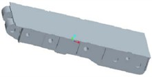
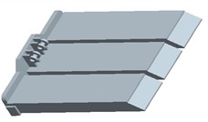
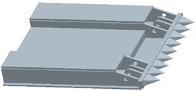
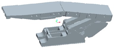
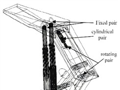
Modeling and analysis are conducted on vertical beam hydraulic supports, which consist of components such as insert plates, guide rods, shield beams, top beams, bases, and columns, as shown in Fig. 1. In order to simplify the analysis process of hydraulic supports, the components are divided into two categories: welded parts and assembled parts. The welded components are connected together through the welding process of steel plates or circular pipes, forming a rigid connection. Therefore, the relative position between each part is fixed and can be fully assembled directly according to the assembly or connection relationship. The assembly of components needs to consider the issue of freedom of motion, and assemble according to the characteristics of rotation. The three-dimensional model of the hydraulic support can be connected to ADAMS and PRO/E through Mech/pro to achieve parameterized conversion of the system dynamics model, making the dynamic and kinematic calculations of the virtual prototype model more efficient. Mech/pro can directly define the rigid body characteristics and related degree of freedom constraints of the model in Pro/E, and transfer them to ADAMS for comprehensive dynamic joint simulation analysis, as shown in Fig. 2. In order to conduct more accurate motion simulation of the hydraulic support, pin connections are used between the four columns and the pin holes at both ends of each oil cylinder, as well as the ear seats on their related components. Sliding connections are used between the piston rod and the cylinder body, between the insert plate and the shield beam, between the guide rod and the guide cylinder, and between the forward beam and the top beam.
Fig. 1The main components of hydraulic support
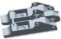
a) Base
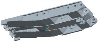
b) Top beam
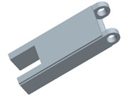
c) Guide rod
d) Cover beam
e) Expansion beam
f) Insertion plate
Fig. 2Model and setting of hydraulic support
a) Assembly structure
b) Degree of freedom setting
2.2. Dynamic characteristics analysis
In the dynamic analysis software ADAMS, open the cmd file to obtain the parameterized virtual prototype model of the hydraulic support. In order to better simulate the kinematic characteristics of hydraulic supports, it is necessary to define the top beam drive motor and set the descent speed to 50 mm/s. The support is set to descend from 2400 mm, and loads are added to the top beam and base according to the support type.
In the load conditions of the virtual prototype of the hydraulic support, the support force applied at both ends of the base is simplified from the support force in the actual working conditions of the base. Therefore, in order to be closer to the actual working conditions, the pressure load of the top beam is dispersed according to the structure. In ADAMS, the lifting motion of the hydraulic support is set as a uniform motion, and the relationship between the dynamic load of the support and time variation is established, so that the dynamic characteristics of the hydraulic support at different heights can be calculated, and the relationship between the bearing capacity of the hydraulic support and the height variation of the support can be studied. After completing the system settings, dynamic simulation analysis can be carried out, and the final curve graphs of the top beam's spatial motion are shown in Fig. 3 and Fig. 4, respectively. The curve shows that the movement of the hydraulic support top beam is relatively stable, and the speed change is relatively gentle. Its maximum horizontal speed is 0.191 m/s, and the acceleration is 0.905 m/s2. During the process of mobile support, the inertia additional force in the horizontal direction is relatively small and the inertia frequency is low for hydraulic supports. In the vertical direction, the motion characteristics of the hydraulic support are similar to those in the horizontal direction, with a flatter and more uniform variation compared to the horizontal direction. The maximum speed is 0.238 m/s and the acceleration is 0.92 m/s2. The additional inertial force is relatively large compared to the horizontal direction. The load on the front link changes significantly, first rapidly decreasing, then gradually remaining stable, before increasing rapidly and finally remaining stable. The angle of the front force column changes little as the support height is reduced. The rear link, on the other hand, shows a curve with sawtooth-like shape, but the changes in its load line are all within 1 kN. From the load curve, it can be seen that the support capacity of this bracket is very stable.
Fig. 3Dynamic simulation results
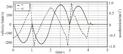
a) Vertical movement of the top beam
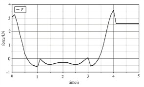
b) Vertical pressure of front connecting rod
2.3. Modal analysis
In order to study the dynamic response of hydraulic supports more accurately, the modules of strength analysis and modal analysis are coupled, that is, the pre-processing, solving, and post-processing settings of static analysis are transmitted to the corresponding analysis steps in modal analysis through data exchange methods. Modal shapes of hydraulic support are shown in Fig. 4. It can be concluded that the maximum displacement of the hydraulic support during vibration mostly occurs at the position of the base, and only the top beam undergoes displacement during 3rd and 4th order vibration, with a displacement value of 0.0710 mm. When the hydraulic support is subjected to vibration, the maximum displacement of orders 2-4 occurs on the top beam, and the first 5 orders of vibration have an impact on the top beam.
2.4. Transient stress analysis
Because the maximum working resistance of the hydraulic support is 9000 kN, a uniformly distributed impact loading of 1.66 MPa is applied to the top beam as prestress. The stress analysis results, as shown in Fig. 5, can be obtained through simulation calculation. The analysis of the stress curve indicates that the highest impact stress is found at the column socket, nearing the yield strength of Q690 material used for the top beam, which is 690 MPa, of which value reaches 640.89 MPa and shows the greatest fluctuation amplitude. It is important to note that while considerable stress fluctuations occur at the junction between the top beam and cover beam, both remain within permissible limits with a maximum stress recorded at 513.36 MPa. Conversely, variations in stress observed in the balance jack are relatively mild and increase steadily, reaching a peak of 475.48 MPa. This suggests that dynamic loads resulting from impacts cause more significant damage to the top beam compared to static loads. When coal rock collides with the top beam, areas of initial contact display marked levels of stress; over time, notable stresses develop in regions such as the column socket of the top beam and pin holes connecting to both balance jacks and shield beams. The subsequent propagation of generated stress waves spreads throughout hydraulic support structures over time. Ultimately, substantial stresses appear in pin holes linking various components: those associated with shield beams as well as front and rear connecting rods-emphasizing that dynamic loading results in wider-ranging damage across entire support systems than static loading does.
Fig. 4Modal shapes of hydraulic support
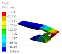
a) The first order (366 Hz)
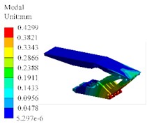
b) The second order (389 Hz)
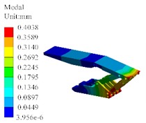
c) The third order (392 Hz)
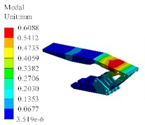
d) The fourth order (438 Hz)
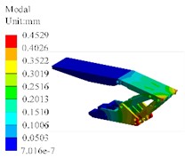
e) The fifth order (499 Hz)
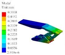
f) The sixth order (512 Hz)
Fig. 5Results of transient stress analysis
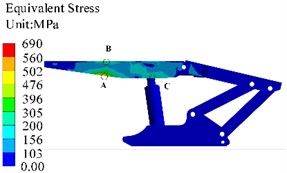
a) Stress contour map
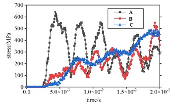
b) Changes in dynamic stress at different nodes
3. Structural optimization of hydraulic supports
3.1. Optimization of multi-link dimensions
For the four-bar linkage structure of hydraulic support, a mechanical analysis model was established, and the structural parameters are shown in Fig. 6. The minimum lateral oscillation value at the end of the top beam is the main optimization target of the genetic algorithm parameterization, i.e., the minimum angular velocity. The optimized parameters obtained by the genetic algorithm were verified by simulation calculation in ADAMS. The accuracy of the results and the speed of the calculation were achieved by the genetic method selected in this paper. The four-bar linkage parameters , ,, , and were optimized for the optimization target.
Fig. 6Structural parameters of multi-link dimensions
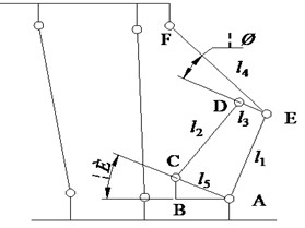
In ADAMS/View, design variables can be used to store data as well as serve as variables in the design process. The main method used to implement parameter variables is Create Design Variable. The type and value of the variable are selected using the variable generation dialog box. The design variables are set to DV_1 (), DV_2 (), DV_3 (), DV_4 (), and DV_5 (). In ADAMS/View, three optimized combination schemes were obtained through continuous iterative calculation, as shown in Table 1. After repeated comparative analysis, the more effective optimization scheme 1 was selected for trajectory simulation. The lateral oscillation value of the end point of the top beam is significantly reduced after optimization, which has important implications for improving the working efficiency of the hydraulic support.
Table 1Results optimized target of multi-link
Scheme | DV_1 (mm) | DV_2 (mm) | DV_3 (mm) | DV_4 (mm) | DV_5 (mm) | (°) |
1 | 1606 | 1511 | 635 | 2043 | 1242 | 1.2 |
2 | 1622 | 1503 | 644 | 2203 | 1252 | 2.2 |
3 | 1602 | 1505 | 645 | 2255 | 1244 | 1.8 |
3.2. Optimization of modal properties
In the optimization analysis, to improve the stiffness and strength of the model, the maximum value of the first-order natural frequency is set as the optimization target, and the minimum value of mass and the minimum value of stress peak are defined as the boundary conditions. The algorithm used for modal optimization calculation is the objective driven optimization method. This method belongs to multi-objective optimization methods and can efficiently process and calculate the optimal design points for multiple sets of parameter variables. In goal driven optimization methods, the selection of initial sample size has a significant impact on the accuracy and efficiency of optimization calculations. Generally speaking, the more samples there are, the higher the computational complexity and accuracy of optimization, but the longer the computation cycle. According to the load-bearing characteristics, the structure of the top beam has the most significant impact on the overall modal behavior. Therefore, with the thickness of the top beam as the design variable, as shown in Fig. 7, the range of up and down fluctuations for each design variable input is set to 20 %, and other preprocessing and grid division are ensured to be consistent with before optimization. The optimized target of thickness of the top beam can be shown in Table 2.
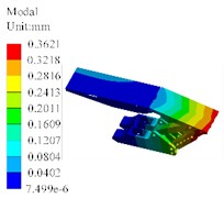
Taking into account the optimization criteria provided by ANSYS and the structural characteristics of the hydraulic support, the third combination of design variables is selected as the final optimization variable, and the corresponding modal vibration results are shown in Fig. 8. The optimization results show that the first natural frequency has increased by 6.0 %, the mass has decreased by 1.6 %, and the stress peak has decreased by 9.9 %.
Table 2Results optimized target of thickness of the top beam
No | th_1 (mm) | th_2 (mm) | th_3 (mm) | Mass / kg | First natural frequency / Hz | Maximum stress / MPa |
1 | 27.73 | 27.26 | 26.26 | 5057 | 375 | 651 |
2 | 27.65 | 27.34 | 24.78 | 5038 | 390 | 673 |
3 | 26.55 | 26.56 | 26.02 | 5034 | 388 | 622 |
Initial value | 30 | 25 | 25 | 5120 | 366 | 690 |
Fig. 7The design variable of top beam
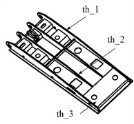
Fig. 8The first order modal shape
4. Conclusions
1) A three-dimensional model of the hydraulic support was established and imported into ADAMS through Mech/Pro. A rigid parameterized model was established, and a virtual prototype model of the hydraulic support was finally obtained. The dynamic characteristics of the hydraulic support were analyzed. In addition, the modal characteristics and stress response results of the hydraulic support were obtained through finite element analysis. It can be seen that based on CAE technology, combined with various computer simulation techniques, comprehensive analysis of the dynamic characteristics of hydraulic supports can be carried out.
2) In order to improve the trajectory efficiency and stability of hydraulic supports, optimization of the linkage mechanism and top beam structure was implemented. By selecting and calculating design variables, objective functions, and constraint conditions, the main four-bar linkage structure of the hydraulic support and the structural dimensions of the top beam were optimized, which improved the trajectory efficiency of the front end point of the top beam of the hydraulic support, and reduced weight and stress peaks while ensuring stable support conditions, thus reducing costs. Modal analysis plays an important role in the optimization process, it can identify the modal parameters of the hydraulic support, providing a basis for optimizing the structural dynamic characteristics and reducing the probability of resonance.
References
-
X. Chen, F. He, F. Chen, and Y. Dai, “Dynamic simulation and experimental study of the effect of one-dimensional vibration on the packing of wood powder particles,” Particuology, Vol. 94, No. 1, pp. 294–304, Nov. 2024, https://doi.org/10.1016/j.partic.2024.08.013
-
X. Liu et al., “Dynamic performance analysis of adsorption heat transformer system driven by large pressure jump for low-grade waste heat upgrade,” Applied Energy, Vol. 377, No. 1, p. 124478, Jan. 2025, https://doi.org/10.1016/j.apenergy.2024.124478
-
Z. Xiong, Y. Yuan, L. Tong, X. Li, and B. Shen, “Dynamic performance analysis of proton exchange membrane fuel cell in marine applications,” Energy, Vol. 310, No. 13, p. 133218, Nov. 2024, https://doi.org/10.1016/j.energy.2024.133218
-
V. Nicoletti, R. Martini, L. Amico, S. Carbonari, and F. Gara, “Operational modal analysis for supporting the retrofit design of bridges,” ce/papers, Vol. 6, No. 5, pp. 1182–1188, Sep. 2023, https://doi.org/10.1002/cepa.2125
-
H. D. Chalak, A. M. Zenkour, and A. Garg, “Free vibration and modal stress analysis of FG-CNTRC beams under hygrothermal conditions using zigzag theory,” Mechanics Based Design of Structures and Machines, Vol. 51, No. 8, pp. 4709–4730, Aug. 2023, https://doi.org/10.1080/15397734.2021.1977659
-
Y. Boudjaada, T. Benmansour, H. E. Fiala, and B. Issasfa, “Experimental and numerical investigation of the honeycomb structures’ effect on the dynamic characteristics of rotors: a modal analysis,” The International Journal of Advanced Manufacturing Technology, Vol. 133, No. 9-10, pp. 4453–4467, Jun. 2024, https://doi.org/10.1007/s00170-024-13875-3
Cited by
About this article
The authors have not disclosed any funding.
The datasets generated during and/or analyzed during the current study are available from the corresponding author on reasonable request.
The authors declare that they have no conflict of interest.
