Abstract
In order to ensure higher structural stability and load safety of the heat exchanger, modal analysis of the folded flow plate assembly was carried out based on the finite element simulation method. In extreme conditions, the stress linearization and evaluation of the tube plate structure were achieved. The models of spiral baffle and traditional single arch baffle components were established, and the first 20 nature frequencies and the first six modal shapes were compared and analyzed. The strength of the tube plate structure was analyzed under the conditions of separate action of tube side pressure and shell side pressure, and the linearization results of stress were obtained through the setting of path. The results indicate that the spiral baffle component has better stability. In addition, through stress decomposition and evaluation, it can be determined that the strength under extreme working conditions meets safety requirements.
Highlights
- In extreme conditions, the stress linearization and evaluation of the tube plate structure were achieved.
- The models of spiral baffle and traditional single arch baffle components were established, and the first 20 nature frequencies and the first six modal shapes were compared and analyzed.
- The strength of the tube plate structure was analyzed under the conditions of separate action of tube side pressure and shell side pressure, and the linearization results of stress were obtained through the setting of path.
1. Introduction
Spiral baffle plate heat exchanger, as an indispensable equipment in industrial processes, has higher heat exchange efficiency compared to traditional heat exchanger. Its stable operation is crucial for ensuring the continuity and safety of the production process. Modal analysis can determine the natural frequency and mode of vibration of a structure by calculating its vibration frequency and shape [1, 2]. In the design and application of heat exchanger, modal analysis can help determine the natural frequency of the heat exchanger, thereby avoiding the occurrence of resonance phenomena caused by matching it with external excitation frequencies during the design phase [3, 4]. Resonance not only affects the normal operation of equipment, but may also cause structural damage. Modal analysis can optimize the design to ensure that the heat exchanger does not resonate under actual working conditions. Through modal analysis, the dynamic characteristics of the heat exchanger can be understood, and its structure can be optimized to reduce vibration and noise, thereby improving the operating efficiency and stability of the heat exchanger [5, 6]. This is of great significance for ensuring the continuity of the production process and product quality. In addition, in order to ensure the strength of the heat exchanger under extreme conditions, a linearized stress solution and verification method has been proposed. Compared with traditional static strength calculation, it can comprehensively consider the impact of load on the equipment, which has the advantages of saving resources and low cost.
2. Modal analysis of heat exchanger baffle components
2.1. Model establishment
Spiral baffle plate heat exchanger is a new type of structure, as shown in Fig. 1, which has stronger fluid disturbance inside, thus enhancing heat transfer efficiency. In order to highlight the dynamic response characteristics of the structure more effectively, the traditional single bow baffle component is also modeled in the article. Through ANSYS simulation calculation, the stability of the baffle under two different structures is compared. Based on the actual dimensions of the structure, Pro/E software was used to model it. At the same time, in order to improve computational efficiency and accuracy, the initial model was simplified, and the final model was determined as shown in Fig. 2. With the development of computer technology, the application of finite element technology has gradually become widespread and popular, which can represent modal characteristics in the form of graphics and images. In addition to seamless integration with CAD software, ANSYS Workbench can also be imported in file formats such as x_t, iges, sat, etc., and there is basically no loss of elements.
Fig. 1Internal structure of heat exchanger

Fig. 2Heat exchanger baffle components
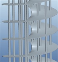
a) Spiral baffle plate component
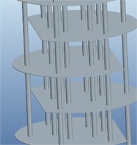
b) Single bow baffle component
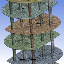
In the preprocessing stage, it is necessary to define the material properties of the model and complete the mesh partitioning. The grid diagram is shown in Fig. 3. For the spiral baffle, there are 88156 elements and 254253 nodes. The traditional bow shaped baffle model generates 30748 elements and 207056 nodes through grid partitioning. Modal analysis has become an essential part of mechanical design. By simulating and calculating modal characteristics, the natural frequencies and modes of vibration of the structure can be obtained, thereby identifying the dangerous positions and states of the mechanical structure during resonance.
Fig. 3Grid division results
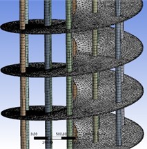
a) Spiral baffle plate component
b) Single bow baffle component
2.2. Discussion on modal analysis results
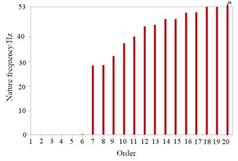
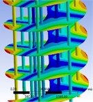
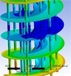
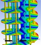
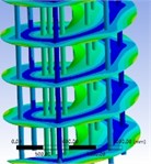
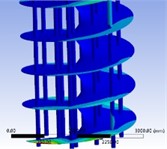
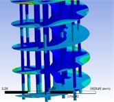
Calculate the first 20 modal characteristics of two different structures separately. Due to the absence of boundary conditions in free mode calculations, the natural frequency values of the first six modes tend to approach 0. The natural frequency variation characteristics of the spiral baffle component are shown in Fig. 4(a). The natural frequency variation within the 20th mode is relatively stable, and the effective lowest resonant frequency is the 7th order, which is 28.2 Hz. The vibration mode cloud map of the spiral baffle component is shown in Fig. 5.
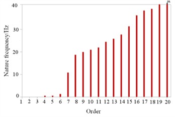
Fig. 4Changes in the first 20 natural frequencies
a) Spiral baffle plate component
b) Single bow baffle component
Fig. 5Modal shapes of spiral baffle plate heat exchanger
a) The first order
b) The second order
c) The third order
d) The fourth order
e) The fifth order
f) The sixth order
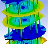
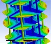
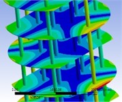
Fig. 6Modal shapes of single bow baffle component
a) The first order
b) The second order
c) The third order
d) The fourth order
e) The fifth order
f) The sixth order
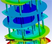
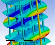
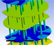
It can be seen that at low order resonance frequencies, the deformation location is mainly at the edge of the helical baffle, which is the main impact point of the fluid. At high-order resonance frequencies, the deformation positions are mainly at the initial and final ends of the baffle. For the bow shaped baffle structure 4, its natural frequency variation characteristics are shown in Fig. 4(b). The fluctuation range of its natural frequency is larger than that of the spiral baffle, so its structure is not stable enough. The effective lowest natural frequency of the bow shaped structure is 10.7 Hz. Therefore, compared to other forms, the bow form is more prone to resonance. The typical vibration mode cloud map of the bow shaped baffle is shown in Fig. 6. During low order resonance, the most intense vibration is located at the top and bottom ends of the baffle. During high-order resonance, the most intense vibration is located at the edge of the bow shaped baffle. In summary, the structure of spiral baffles is more stable than that of ordinary bow baffles, and can ensure safer and more normal use when subjected to fluid impact and vibration.
3. Dynamic stress analysis of tube plate under extreme conditions
3.1. Model establishment and boundary condition setting
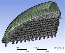
The structure connecting the tube plate, tube box head, and shell side cylinder in the heat exchanger is the core load-bearing component, so the strength verification of the connection structure is very necessary. Due to the symmetrical structure of the tube plate, establishing a quarter model can effectively improve computational efficiency. Import the three-dimensional model of the established tube plate through seamless connection interface with ANSYS, as shown in Fig. 7(a), and then set physical properties of the model, including density, elastic modulus, Poisson's ratio, etc. Apply hexahedral partitioning method to mesh the head and cylinder, and use tetrahedral partitioning method to mesh the tube plate. The result of grid division is shown in Fig. 7(b), which contains 51289 elements and 99617 nodes.
Fig. 7Finite element model of tube plate
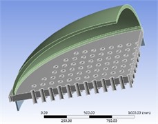
a) 3D model of tube plate
b) Grid division results
3.2. Linearized stress analysis with limit of tube load
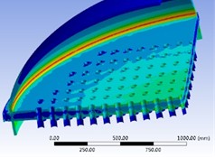
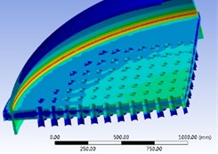
Under extreme load, there are two separate effects of tube side pressure and shell side pressure. When the shell side pressure acts alone, the load borne by the upper surface of the tube plate, the inner surface of the cylinder, and the outer surface of the heat exchange tube is 0.39 MPa. By analyzing the results, it can be concluded that the stress and strain distribution of the tube plate under only shell side pressure is shown in Fig. 8. It can be seen that the maximum stress value of the tube plate is 231.99 MPa, which is located at the connection between the tube plate and the cylinder. In addition, the stress value at the connection between the cylinder and the tube plate on the inner side of the shell side is lower than the pressure value on the tube side.
Fig. 8Analysis results of static strength with limit of tube load
a) Stress cloud map
b) Strain cloud map
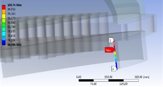
Fig. 9The result of stress linearization with limit of tube load
a) Path setting
b) Decomposition of stress
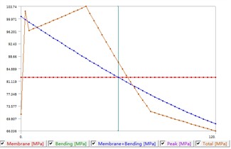
The prerequisite for conducting stress evaluation is to linearize the overall stress experienced by the tube plate by selecting an appropriate path. Select the maximum evaluation stress path to conduct evaluation analysis on the connection between the cylinder and the tube plate. After loading and stress calculation, stress linearization can be continued from the calculation results and further calculations can be performed, as shown in Fig. 9. The results indicate that the maximum evaluation stress occurs at the end of the path, which is the lower edge of the weld seam. However, this is the connection between two components, and the structure is not continuous. Therefore, when conducting stress analysis at this location, one should consider the local membrane stress and the sum of the primary and secondary stresses. For the two selected paths, the maximum value of the first local thin film stress reached 82.69 MPa, and the maximum value generated by the sum of the first and second stresses PS is 103.74 MPa. According to the evaluation criteria, 1.5 230.6 MPa, 3 = 461.2MPa, where is assessment stress. Therefore, when only the tube side pressure is applied to the pressure vessel, the structure at the joint between the cylinder and the tube plate weld is quite safe.
3.3. Linearized stress analysis with limit of shell load
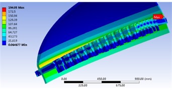
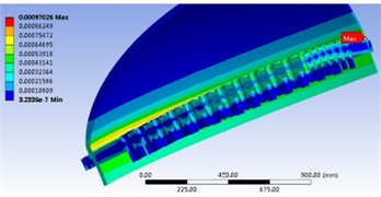
Considering the ultimate load capacity of the heat exchanger, analyze the impact of the ultimate load on the strength of the entire tube sheet structure when only the tube side pressure is applied. Set the tube side pressure in the heat exchanger to 0.45 MPa. According to the analysis results, the distribution of stress and strain in the tube plate with the independent action of tube side pressure can be obtained shown in Fig. 10. The maximum stress generated by the tube plate is 194.05 MPa, which is located at the connection between the cylinder and the tube plate. In addition, the stress value at the weld joint between the cylinder and the side tube plate is greater than that at the weld joint on the inner side of the shell side. The connection between the cylinder and the tube plate structure will generate edge stress due to the discontinuity of the structure, known as the discontinuity effect, resulting in the maximum stress value at this point.
Fig. 10Analysis results of static strength with limit of shell load
a) Stress cloud map
b) Strain cloud map
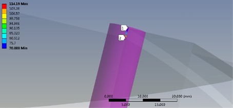
After loading and stress calculation, stress linearization with limit of shell load can be performed, as shown in Fig. 11. For the selected paths, the maximum value of the first local thin film stress reached 42.16 MPa, and the maximum value generated by the sum of the first and second stresses is 114.19 MPa. According to the evaluation criteria, 230.6 MPa, 461.2 MPa, where is assessment stress. Therefore, when only the shell side pressure is applied to the pressure vessel, the structure at the joint between the cylinder and the tube plate weld is also safe.
Fig. 11The result of stress linearization with limit of shell load
a) Path setting
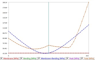
b) Decomposition of stress
4. Conclusions
1) Based on the finite element method, the modal characteristics of two different heat exchanger structures were analyzed and compared. It can be verified that the vibration mode of the spiral baffle plate heat exchanger is more balanced, and therefore can resist stronger external excitation loads. From this, it can be seen that both in terms of heat transfer efficiency and stability, the spiral baffle structure is superior.
2) Global strength analysis and local stress linearization are applied to stress assessment and safety verification. When only the shell and tube side pressure acts on the heat exchanger, it belongs to the extreme working condition. Through stress linearization and evaluation, it can be concluded that the tube plate structure under existing loads and design dimensions is in a safe state. Therefore, under normal working conditions, it can be inferred that the structure of the heat exchanger is stable and can effectively meet different usage requirements.
References
-
H. D. Chalak, A. M. Zenkour, and A. Garg, “Free vibration and modal stress analysis of FG-CNTRC beams under hygrothermal conditions using zigzag theory,” Mechanics Based Design of Structures and Machines, Vol. 51, No. 8, pp. 4709–4730, Aug. 2023, https://doi.org/10.1080/15397734.2021.1977659
-
R. K. Bhamu, A. Shukla, S. C. Sharma, and S. P. Harsha, “Vibration response of steam turbine healthy and cracked blade under the stress stiffening and spin softening effects,” Proceedings of the Institution of Mechanical Engineers, Part K: Journal of Multi-body Dynamics, Vol. 236, No. 2, pp. 224–243, Feb. 2022, https://doi.org/10.1177/14644193221078656
-
W. Wu, L. Hu, and Z. Zhang, “Collaborative optimization of nonlinear hydropneumatic suspension dynamic characteristics,” Journal of Testing and Evaluation, Vol. 48, No. 2, pp. 825–837, Mar. 2020, https://doi.org/10.1520/jte20180506
-
V. Nicoletti, R. Martini, L. Amico, S. Carbonari, and F. Gara, “Operational modal analysis for supporting the retrofit design of bridges,” ce/papers, Vol. 6, No. 5, pp. 1182–1188, Sep. 2023, https://doi.org/10.1002/cepa.2125
-
D. Yang et al., “Modelling and prediction on the modal and harmonic response of helix tube in large-scale spiral-wound heat exchangers,” Engineering Failure Analysis, Vol. 148, No. 1, p. 107186, Jun. 2023, https://doi.org/10.1016/j.engfailanal.2023.107186
-
V. N. Khmelev, D. S. Abramenko, D. V. Genne, V. A. Nesterov, R. V. Barsukov, and S. A. Tsyganok, “Investigation of modes and conditions for superimposing ultrasonic vibration on heat exchangers,” Journal of Physics: Conference Series, Vol. 1679, No. 2, p. 022011, Nov. 2020, https://doi.org/10.1088/1742-6596/1679/2/022011
About this article
The authors have not disclosed any funding.
The datasets generated during and/or analyzed during the current study are available from the corresponding author on reasonable request.
The authors declare that they have no conflict of interest.
