Abstract
The dynamics and modal characteristics are important basis for the stable operation of vibrating screen. A multi-body dynamic model of vibrating screen was established based on ADAMS, and the laws of change in the center of mass and the dynamic response of the vibration isolation system were obtained. The amplitude-frequency response results of acceleration under varying stiffness and damping coefficients were compared and analyzed, providing a crucial foundation for enhancing vibration isolation performance. The vibrating screen was analyzed for its modal characteristics using ANSYS, and the natural frequencies and vibration patterns were investigated. The distribution and main causes of the maximum resonance displacement were discussed. Drawing on the results of stress and modal shapes, the strength of the vibrating screen was significantly enhanced through multi-objective optimization methods without increasing its weight. The findings indicate that the optimized structure can achieve a 32.2 % reduction in peak stress.
Highlights
- A multi-body dynamic model of vibrating screen was established based on ADAMS, and the laws of change in the center of mass and the dynamic response of the vibration isolation system were obtained.
- The amplitude-frequency response results of acceleration under varying stiffness and damping coefficients were compared and analyzed, providing a crucial foundation for enhancing vibration isolation performance.
- The vibrating screen was analyzed for its modal characteristics using ANSYS, and the natural frequencies and vibration patterns were investigated.
1. Introduction
In the production process of sand and gravel aggregate, a vibrating screen is needed to remove the soil attached and mixed with the ore during mining. The vibrating screen works by the reciprocating rotary vibration generated by the vibrator, so the dynamic characteristics have a very critical impact on the performance [1, 2]. In today’s constantly developing machinery and construction industry, the quality and requirements of sand and gravel aggregates are becoming increasingly high, and there is a need to develop and manufacture higher performance sand and gravel aggregate screening equipment and processing equipment. Therefore, it is necessary to analyze the dynamic characteristics of the vibrating screen, especially kinematic response and modal characteristics under vibration excitation, which are important indicators for measuring the performance of the isolation system [3, 4]. Generally speaking, in order to achieve greater screening processing capacity and screening efficiency, greater excitation force is required [5]. However, the problems caused by the increasing excitation force have become more apparent, making it increasingly difficult to ensure the stability and reliability of the vibrating screen. The insufficient structural stiffness and strength, such as deformation of the screen body, tearing of the side plate, and fracture of the crossbeam, have become important reasons for seriously reducing the service life of the vibrating screen. Modal analysis can verify whether the mechanical structure is in the resonance region, identify weak or reinforcement-needed areas, which is crucial for directed optimization. Therefore, a multi-objective optimization method has been proposed that can significantly reduce stress peaks and improve strength characteristics without increasing weight.
2. Simulation and analysis of dynamic characteristics
2.1. Model establishment
Vibration screening equipment, as shown in Fig. 1(a), mainly consists of three parts: excitation vibration device, screen body, and isolation system, as shown in Fig. 1(b). The excitation device generates periodic inertia excitation force, which enables the screen to continuously undergo periodic vibration. The screen body undergoes periodic motion due to the inertial excitation force generated by the vibration device, carrying the flow of animal material and passing through the screen to complete the screening process. The main function of the isolation system is to support the vibrating screen body and screen material, so that the screen body can vibrate at a specific amplitude and reduce the dynamic load transmitted to the foundation or structural support. Dynamics analysis is mainly used to study the motion of vibration systems under external loads. By establishing a dynamic model of the vibrating screen, the motion law of the vibrating screen in a stable motion state can be obtained. Export the 3D model created and assembled in SolidWorks to the parasolid file format. Import the exported file into ADAMS, set the gravity in the working environment in ADAMS/view, connect the components using Boolean operations, and set the density of each component based on its material properties. According to the actual operation of the vibrating screen, set constraint pairs on the simulation model in the constraint interface, as shown in Fig. 1(c). A fixed pair is set between each support seat of the vibrating screen and the ground, and a rotating pair is set between the excitation shaft and the bearing seat. A single row cylindrical roller bearing is installed at the corresponding position between the excitation shaft and the bearing seat, connected by a bearing between the excitation shaft and the bearing seat. A synchronous device is installed on one side of the excitation shaft for forced synchronization. Therefore, a synchronous belt and a synchronous wheel are set up, and the synchronous wheel is connected to one side of the excitation shaft.
Fig. 1Model and setting of hydraulic support
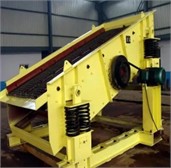
a) Assembly structure
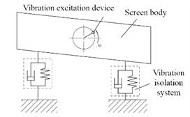
b) Degree of freedom setting
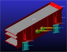
c) Model
2.2. Dynamic characteristics analysis of mass center
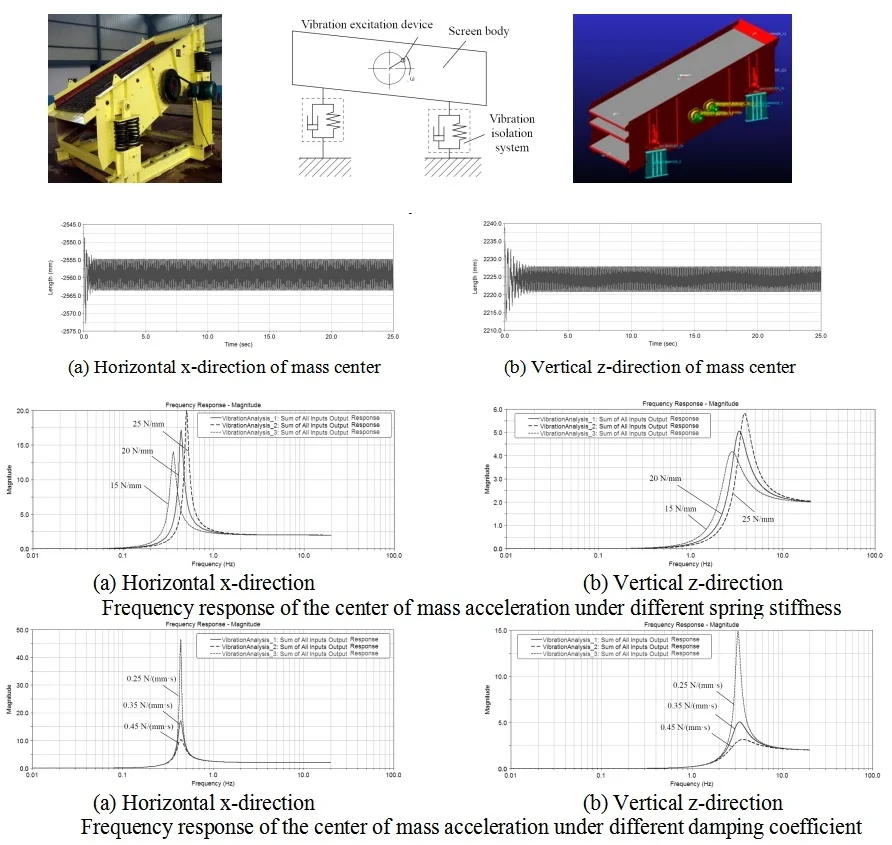
Set the simulation time to 25 seconds and iterate the calculation steps to 10000. After the simulation calculation is completed, the dynamic data of the vibrating screen can be exported and processed accordingly through the ADAMS post-processing module. Fig. 2 shows the variation law of displacement over time in the vertical y-direction and horizontal -direction at the center of mass of the vibrating screen body.
Fig. 2The motion law of the center of mass
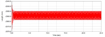
a) Horizontal -direction of mass center
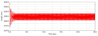
b) Vertical -direction of mass center
According to the simulation results, it can be seen that the displacement change of the vibrating screen is relatively large during the start-up stage. This is because the vibrating screen is subjected to the combined action of free vibration and forced vibration during this stage, and the amplitude changes dramatically. After running for a period of time, the motion of the vibrating screen gradually stabilizes, and the -direction and -direction displacements show obvious periodic changes. Due to the gradual attenuation of free vibration with the operation of the vibrating screen until it reaches zero, the vibrating screen is only subjected to forced vibration during stable operation. During the start-up phase of the vibrating screen, the amplitude in the -direction is greater than that in the direction. This is due to the fact that the vertical stiffness and damping coefficients of the vibrating screen rubber spring are greater than those in the horizontal direction.
2.3. Vibration response analysis of isolation system
The isolation system of the vibrating screen includes an upper support seat, a lower support seat, and a rubber spring. By simplifying the rubber spring into a spring and damping unit, the spectral response results of the center of mass acceleration under different spring stiffness and damping coefficient conditions can be obtained, as shown in Fig. 3 and Fig. 4.
Fig. 3Frequency response of the center of mass acceleration under different spring stiffness
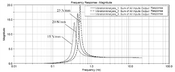
a) Horizontal -direction
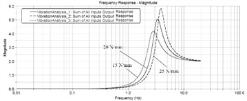
b) Vertical -direction
Fig. 4Frequency response of the center of mass acceleration under different damping coefficient
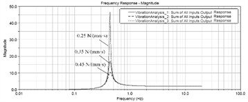
a) Horizontal -direction
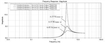
b) Vertical -direction
It can be seen that the spring stiffness can significantly affect the natural frequency and vibration amplitude of the entire vibrating screen. Within a certain range, the higher the spring stiffness, the higher the natural frequency, and the corresponding amplitude. The damping coefficient does not affect the natural frequency of the system, but it greatly reduces the amplitude under resonance conditions. Rubber spring is an elastic component of damping support device, which achieves spring, vibration reduction and isolation effects through the elastic deformation of rubber. Rubber springs have good damping, sound insulation, and wear resistance, with a small elastic modulus and excellent nonlinear characteristics. They can withstand strong impact loads, absorb high-frequency vibrations and noise well, are easy to install and disassemble, and can withstand compression and shear deformation. Although the stiffness of rubber springs can meet the normal operation requirements of vibration screening equipment, their high damping characteristics can significantly attenuate the dynamic amplification factor of the system, and once produced and formed, it is difficult to fine tune the stiffness and damping. Under long-term exposure to high dynamic loads, aging, relaxation, and bulging phenomena are prone to occur, affecting work efficiency and screening effectiveness. When there is a significant height or stiffness difference between rubber springs, the vibrating screen may even exhibit lateral motion, affecting the normal operation of the equipment and the stability of the vibration system. When the vibrating screen undergoes periodic vertical downward vibration, the excitation force will be greater than the weight of the vibrating screen, and the upper support seat and rubber spring will periodically detach and collide, resulting in noise.
2.4. Modal analysis of screen body
In order to obtain the dynamic characteristics of the screen body, modal analysis is required. The finite element analysis model of the vibrating screen body is established, and the required modal vibration mode solving parameters are set. The Subspace method is used for modal solving operations. Under actual constraints, extract the first 6 modes of the vibrating screen after the calculation is completed as shown in Fig. 5 and Table 1. It can be seen that under the first order fixed frequency condition, the screen body begins to undergo bending deformation, and the maximum vibration displacement is located at the center of the two side clamping plates, which is related to the structural stiffness. At the second and third natural frequencies, the maximum amplitude is distributed on the supporting rod at the edge. The most significant deformation structure in the remaining modal shapes of the vibrating screen is the reverse twisting of the discharge end along the -axis, followed by the serpentine twisting around the exciter along the -axis. The main reason for this vibration pattern is that the stiffness of the discharge port is too small and the structure is not reasonable enough. In addition, the distribution of reinforced angle steel on the side plate is uneven.
Table 1Natural frequency and vibration mode
Order | Natural frequency / Hz | Description of vibration modes |
1 | 7.39 | Swing left and right along the -axis and rotate around the -axis |
2 | 11.26 | Bend and swing along the -axis direction |
3 | 11.87 | Swing left and right along the -axis and twist slightly around the -axis |
4 | 17.43 | Swing left and right along the -axis in the middle |
5 | 21.22 | Swing slightly around the -axis direction |
6 | 25.25 | Swing left and right along the -axis direction |
Fig. 5The first six modal shapes
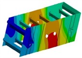
a) The first order
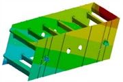
b) The second order
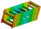
c) The third order
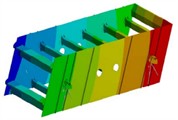
d) The fourth order
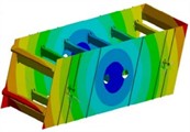
e) The fifth order
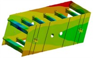
f) The sixth order
3. Strength optimization of screen body
3.1. Strength analysis under ultimate load
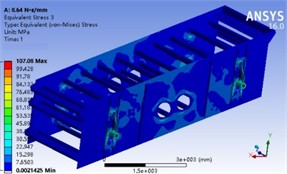
The quality of the grid directly affects the speed and accuracy of simulation solutions. Due to the large size and numerous components of the vibrating screen, automatic mesh division was first used to partition the entire machine. Structures that are prone to damage are subjected to mesh refinement, while other parts maintain the size of the automatically partitioned mesh, as shown in Fig. 6. The method of local refinement can ensure the accuracy of simulation results, reduce simulation computational complexity, and improve computational efficiency. The distribution of stress is shown in Fig. 7. It can be seen that the stress on the screen body is mainly concentrated on the supporting beams and the side plates near the excitation device. The stress at the connection between the supporting tube and the reinforcing rib of the supporting beam is the highest, with a maximum value of 107.08 MPa. As the supporting beam is a supporting structure connecting the screen box and the damping support device, it not only bears the mass of the screen body and the material during operation, but also the dynamic load composed of the excitation force generated by the excitation device and the inertia force of the screen body, which is transmitted to the damping support device, resulting in a high stress on the supporting beam.
Fig. 6Finite element mesh division results
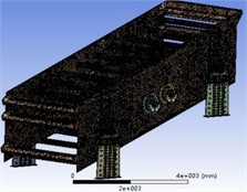
Fig. 7Overall stress field cloud map
3.2. Discussion on optimization schemes
According to the simulation analysis of the stress and modal vibration mode of the vibrating screen, it is known that the stress of the vibrating screen body is relatively high at the position of the support beam and the side plate near the excitation device, and the maximum stress of the support beam is close to the allowable stress. After long-term use, structural damage may occur, and the deformation of the two crossbeams near the lower excitation device and the side plate near the excitation device is relatively large. There is a certain problem of uneven structural distribution in the side plate of the vibrating screen. Therefore, on the basis of improving stress, a certain degree of lightweight improvement is proposed for the vibrating screen. In order to improve the stiffness and strength of the vibrating screen mechanical structure without increasing the manufacturing cost, the maximum value of the first-order natural frequency is set as the optimization target, and the minimum value of the mass and the minimum value of the stress peak are defined as the boundary conditions.
Fig. 8Structural parameters of design variables
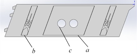
Fig. 9Optimized stress cloud map
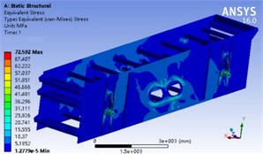
To enhance the structural strength of the side plate exciter position, improve stress distribution, and reduce deformation, the strengthening plate length , rib spacing , and pulley aperture are used as design variables, as shown in Fig. 8. For optimization algorithms, the response surface function method is chosen. Based on the characteristics of the design variables, the Latin hypercube DOE method was used to generate sample points, with a total of 15 points sampled to achieve approximate model fitting. Optimization is based on a model constructed with limited sample points, so the characteristic of this method is that the optimization time is fast, but it sacrifices some accuracy, which can be compensated for through secondary validation. According to engineering practice, the response function of stress has significant complex nonlinear characteristics. By fitting the regression function in the text and combining it with advanced optimization algorithms, the maximum target variable within the design variable range can be efficiently searched. Essentially, the optimization of separation performance is achieved through mathematical calculations to optimize parameter allocation and obtain the minimum stress peak and mass. The search for target extremum belongs to a typical iterative algorithm. To improve the stability of the calculation process and achieve global convergence, the total sample size can be defined first, and then the linear search factor can be combined with the Lagrangian value function to obtain a reasonable iteration step size. In the self adjustment of convergence speed, it is necessary to change the iteration step size according to the accuracy judgment criteria. Through continuous iterative calculations, the results of the design variables and optimization objectives can be obtained as shown in Table 2, and the optimized stress cloud map is shown in Fig. 9. It can be seen that on the premise that the mass remains basically unchanged, the maximum stress value can be decreased from 107.08 MPa to 72.59 MPa, with a reduction rate of 32.2 %. The first natural frequency has slightly increased. Compared with the stress distribution of the sieve body before improvement, the stress distribution is roughly the same, but the maximum stress value of the vibrating sieve body has been effectively reduced, indicating that the stress concentration of the structure can be effectively reduced, the stiffness can be improved, and there is sufficient redundancy with the allowable stress, which can be used for long-term operation. This indicates that the structural improvement scheme is very effective.
Table 2Optimized results
Parameter | / m | / mm | / mm | Mass / kg | Maximum stress / MPa | First natural frequency / Hz |
Initial value | 1.62 | 20 | 25 | 3234 | 107.08 | 7.39 |
Optimized values | 1.57 | 23.36 | 27.33 | 3219 | 72.59 | 9.44 |
4. Conclusions
Through multi-body dynamics analysis, the displacement and acceleration curves of the center of mass of the vibrating screen were obtained based on ADAMS, and the reasons for the differences in motion characteristics under different isolation parameters were analyzed. In addition, through finite element analysis, the modal characteristics of the screen body were obtained based on ANSYS, including the variation laws of natural frequencies and vibration modes. The results indicate that during the start-up phase of the vibration screen, the amplitude in the -direction is greater than that in the -direction. Under low order natural frequency conditions, the maximum vibration displacement mainly occurs at the center of the side plate.
Based on the stress and modal analysis results, the side panel was selected as the optimization object. Through multi-objective optimization methods, the stress peak was effectively reduced by more than 30 % without increasing weight, while also increasing the natural frequency. The optimal design of the structure plays an important role in improving the reliability of vibrating screen that work continuously for a long time.
References
-
H. Lu et al., “Dynamic simulation and active vibration control design of an ultra-precision fly-cutting machine tool,” The International Journal of Advanced Manufacturing Technology, Vol. 133, No. 9-10, pp. 4663–4678, Jun. 2024, https://doi.org/10.1007/s00170-024-13996-9
-
P. Shi, Z. Liu, M. Li, X. Xu, and D. Han, “Nonlinear dynamics analysis of enhancing energy harvesting from intense vibration based on improved asymmetric bistable stochastic resonance model,” Chinese Journal of Physics, Vol. 90, No. 1, pp. 223–236, Aug. 2024, https://doi.org/10.1016/j.cjph.2023.05.004
-
W. Wu, L. Hu, and Z. Zhang, “Collaborative optimization of nonlinear hydropneumatic suspension dynamic characteristics,” Journal of Testing and Evaluation, Vol. 48, No. 2, pp. 825–837, Mar. 2020, https://doi.org/10.1520/jte20180506
-
V. Nicoletti, R. Martini, L. Amico, S. Carbonari, and F. Gara, “Operational modal analysis for supporting the retrofit design of bridges,” ce/papers, Vol. 6, No. 5, pp. 1182–1188, Sep. 2023, https://doi.org/10.1002/cepa.2125
-
D. Yang et al., “Modelling and prediction on the modal and harmonic response of helix tube in large-scale spiral-wound heat exchangers,” Engineering Failure Analysis, Vol. 148, No. 1, p. 107186, Jun. 2023, https://doi.org/10.1016/j.engfailanal.2023.107186
About this article
The authors have not disclosed any funding.
The datasets generated during and/or analyzed during the current study are available from the corresponding author on reasonable request.
The authors declare that they have no conflict of interest.
