Abstract
The dynamic response of the box and suspension system is one of the most important factors affecting the vibration and noise of the washing machine. To ensure the accuracy of dynamic analysis, a rigid-flexible coupling model was put forward and established, enabling the acquisition of the load responses of flexible box and the dynamic characteristics of suspension system. The free vibrations of the washing machine box were analyzed, and the effective natural frequencies and modes were obtained. The modal neutral file was imported into ADAMS, where the rigid elements were replaced and spring and damping constraints were set. The dynamic responses of the center of mass displacement and load of the suspension system under different spring stiffness and damping system conditions were analyzed, which can provide important basis for optimizing the vibration isolation performance. The results show that the first-order natural frequency of the box exceeds the maximum excitation frequency, and the maximum stress is mainly distributed in the joints of the sheet metal.
Highlights
- To ensure the accuracy of dynamic analysis, a rigid-flexible coupling model was put forward and established.
- The modal neutral file was imported into ADAMS, where the rigid elements were replaced and spring and damping constraints were set.
- The dynamic responses of the center of mass displacement and load of the suspension system under different spring stiffness and damping system conditions were analyzed.
1. Introduction
According to the working principle of the washing machine, the clothes will rotate eccentrically in the inner drum, causing the washing drum to be stimulated by variable loads and directional inertial forces, which can cause severe vibration of the entire machine. The vibration of the entire machine not only generates significant noise, but also affects the lifespan of the mechanical and electrical components [1, 2]. When running at low speed, the lifting ribs will drive the clothes to a high place and cause them to fall, which will have an impact on the inner cylinder. When the inner cylinder accelerates from rest to high speed, the system will experience resonance at a certain speed stage, causing severe vibration of the cylinder suspension system, which can easily lead to collisions between the cylinder and the box or other internal parts. When the inner cylinder is in the high-speed dehydration stage, the eccentric excitation generated by the eccentric clothing inside at high speed will be transmitted to the box through the suspension system, causing vibration and noise in the box. The vibration generated by the drum washing machine not only affects the service life of the product itself, but also affects the user experience and even causes harm [3, 4]. Conventional dynamic analysis cannot consider the vibration response caused by flexible enclosures, resulting in certain deviations from actual operating conditions [5, 6]. Therefore, a rigid flexible coupling model is proposed. Through modal analysis of the flexible box, a virtual prototype model of dynamic response can be established to ensure the accuracy and reliability of vibration analysis, which can provide reliable basis for the evaluation of the working state of the washing machine and the optimization of its performance.
2. Establishment of rigid flexible coupling model
2.1. Model establishment and flexible processing
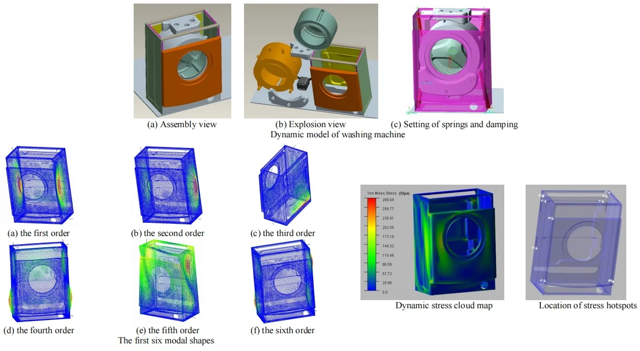
Based on the principle of analyzing the main factors and weakening the secondary factors, a virtual prototype model as shown in Fig. 1 was established according to the actual product characteristics of the washing machine. Each model component contains corresponding quality attributes, and the main parts in the model include: box, inner cylinder, outer cylinder, upper counterweight, lower counterweight, motor, eccentric mass, etc. All key components of the washing machine vibration system, except for springs and dampers, have their own mass characteristics. The spring and damper models are implemented through parameter feature settings. In terms of model simplification, the model components omit features such as holes and chamfers that have little impact on the dynamic characteristics of the model. At the same time, mechanical parts that have little impact on the dynamic characteristics of the washing machine are ignored in the assembly. However, while simplifying the model, it is necessary to ensure that the mass, center of gravity, and moment of inertia of key components remain unchanged. This can be achieved by setting the shape and density of the model, as shown in Fig. 1(c).
Fig. 1Dynamic model of washing machine
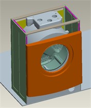
a) Assembly view
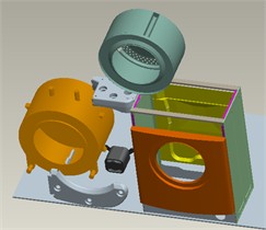
b) Explosion view
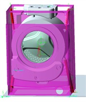
c) Setting of springs and damping
Fig. 2Establishment of coupling model
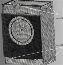
a) Establishment of modal neutral file
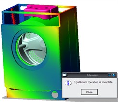
b) Flexible processing
The parameters of the washing machine box model were set in the finite element analysis software ANSYS. As presented in Table 1, Shell63 and Mass21 were selected as the element types. Given that the box body is constituted by sheet metal parts, Shell63 elastic shell elements were employed to divide the grid. Shell63 elements possess bending capability and thin film force, can withstand plane and normal loads, and also have the capacity for stress stiffening and large deformation. The Mass21 element simulates the transmission of connecting forces with an extremely small mass, with its mass and moment of inertia properties being set to 1e-6. Four key-points were established based on the suspension points of the spring and damper, and Mass21 elements were utilized to mesh them. The grid size of the box was set to 11 mm, Shell63 elements were employed for grid division, and eventually a grid number of 37389 and a node number of 36679 were obtained, as shown in Fig. 2(a). Rigid flexible coupling requires replacing the rigid body of the box with the generated modal neutral file. To ensure the accuracy of structural analysis, it is necessary to set the “align flex body CM with CM of current part”, that is, to determine that the centroids between the two are coincident. After the rigid flexible coupling, expired constraints will appear on the model, so further constraint settings are needed to obtain the rigid flexible coupling model as shown in Fig. 2(b).
Table 1Parameter settings
Element type | Density (kg/m3) | Elastic modulus (MPa) | Poisson’s ratio | |
Shell63 | Mass21 | 7800 | 2e5 | 0.3 |
2.2. Dynamic characteristics analysis of flexible box body
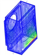
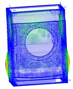
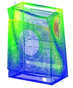
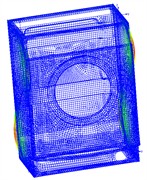
The natural frequency of the flexible box is presented in Table 2. It can be observed that the first natural frequency value is 43.2 Hz, which is far from the maximum excitation frequency of 20 Hz in the system. Hence, the box will not resonate. However, with the escalating demand for the maximum dehydration speed in the consumer market, it implies that the excitation frequency will approach the resonance frequency of the box. Therefore, in the next step of the box design, its stiffness needs to be further enhanced through various means and methods. The first six modal shapes are presented in Fig. 3. It can be observed that the side walls of the box, the front door opening, and the bottom of the rear wall are the main resonance areas and also the parts that require reinforcement in the structure. The vibration mode of a flexible box is essentially the characteristic vector of the modal equation, which corresponds one-to-one with the natural frequency and theoretically has an infinite number. The manifestation of the vibration mode of the box after modal calculation in the finite element software is structural deformation. However, the deformation on the box structure is only a relative quantity, not the actual deformation. That is to say, the maximum relative deformation under resonance represented by the vibration mode.
Table 2Nature frequency
Order | 1 | 2 | 3 | 4 | 5 | 6 |
Nature frequency / Hz | 43.2 | 46.4 | 55.3 | 60.8 | 77.4 | 80.5 |
Fig. 3The first six modal shapes
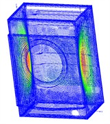
a) The first order
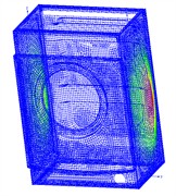
b) The second order
c) The third order
d) The fourth order
e) The fifth order
f) The sixth order
Owing to the constantly varying excitation force generated by springs and dampers on the box, the structural analysis of the box cannot merely rely on static analysis but requires dynamic analysis. Through the durability module in ADAMS, it is straightforward to obtain the dynamic stress and hotspot positions of the entire system during operation, as respectively shown in Fig. 4 and Fig. 5.
As presented in Table 3, the maximum dynamic stress of the box can be determined by analyzing the force information at these positions. It can be perceived that the location of the highest stress is generally distributed at the end nodes between the parts. Therefore, in actual production, the connection structure of these nodes needs further reinforcement and inspection.
In theory, there are countless natural frequencies and vibration modes of a flexible box. However, in modal calculations, the higher the order of the mode, the greater the error. Therefore, the first six or so modes of the system are used for analysis The flexible box of a washing machine, as a thin-walled component with a side plate thickness of less than 1mm, has relatively low overall stiffness. When subjected to forces transmitted by the suspension system, deformation and vibration cannot be ignored. By establishing a finite element model for quantitative analysis, and directly using modal parameters for modeling and analysis, it is faster and more convenient.
Fig. 4Dynamic stress cloud map
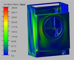
Fig. 5Location of stress hotspots
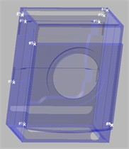
Table 3Dynamic stress information of hotspots
Top 15 hot spots | Abs | Radius = 0.0 mm | ||||
Hot spot | Stress (Newton/Mm2) | Node id | Time (sec) | Location wit LPRF (mm) | ||
# | X | Y | Z | |||
1 | 854.55 | 5157 | 4.725 | –1 | –296.605 | –347.9 |
2 | 835.03 | 4603 | 6.335 | –340.939 | –278.2 | 274.347 |
3 | 830.905 | 2122 | 3.43 | -1 | 297.485 | –347.9 |
4 | 739.545 | 14491 | 6.335 | –288.17 | 276 | 330 |
5 | 658.106 | 4941 | 5.075 | –1.88 | –296.5 | 202.4 |
6 | 648.983 | 2123 | 4.725 | –1 | 296.605 | –347.9 |
7 | 631.234 | 2120 | 5.075 | –1.88 | 296.5 | 347.9 |
8 | 621.932 | 2121 | 3.43 | –1.88 | 297.5 | –347.9 |
9 | 610.605 | 1356 | 6.335 | –340.978 | 278.2 | 273.54 |
10 | 594.707 | 5159 | 3.185 | –1.88 | -297.5 | –347.9 |
11 | 588.652 | 29080 | 2.975 | –343.88 | 251.569 | 229.6 |
12 | 569.691 | 4610 | 6.335 | –340.998 | –278.2 | 280.535 |
13 | 566.436 | 4938 | 5.11 | –1 | –296.605 | 202.4 |
14 | 541.045 | 27008 | 3.15 | –343.38 | –251.435 | 229.1 |
15 | 537.165 | 4608 | 2.975 | –341.113 | –278.2 | –184.396 |
3. Vibration analysis of washing machine suspension system
3.1. Dynamic response under different spring stiffness
The stiffness and damping coefficient of the spring are crucial for vibration reduction in the entire suspension system, and rational parameter selection can better attain the vibration isolation effect. If the stiffness of the spring is overly high, it will cause excessive force to be transmitted to the box, which will not only impact the structural stability of the box but may also result in the displacement of the entire body. Conversely, if the spring is too small, it will lead to excessive vibration of the outer cylinder inside the box and even impact the box. Dampers are also of great significance in vibration isolation as they can suppress severe vibrations of the system when it approaches or undergoes its natural frequency. However, the isolation effect is not remarkable when the system is stable.
To investigate the influence of the stiffness coefficient of the spring k on the dynamic characteristics of the suspension system, a comparison was conducted between two cases of k= 7.5 N/mm and k= 10 N/mm, and the displacement of the center of mass and the variation law of the spring tension were obtained, as depicted in Fig. 6. When the system reaches a steady state, an increase in the spring's stiffness leads to greater fluctuations in vibration amplitude. This also indicates that as the spring's stiffness coefficient rises, the natural frequency of the system increases while its damping effect deteriorates. Furthermore, with a higher stiffness coefficient for the spring, there is a notable rise in force acting on the box structure, particularly at its maximum load point – known as the resonance point. the force experienced at the suspension points of the box is directly influenced by the spring’s stiffness; thus, under identical excitation forces, an increase in spring stiffness will inevitably result in a corresponding increase in force on the box body.
Fig. 6Dynamic response under different spring stiffness
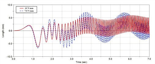
a) Change in the center of mass displacement
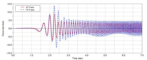
b) Change in spring tension (the upper suspension point)
3.2. Dynamic response under different damping coefficient
Dampers play a role in energy dissipation in vibration isolation, which can convert the energy of system vibration into heat. At the same time, dampers can also buffer high-speed amplitudes. the vibration response results can be obtained when the damper coefficient c is 0.15 N/(mm·s) and 0.25 N/(mm·s), as shown in Fig. 7.
Based on the dynamic analysis outcomes, when the damping coefficient is increased, the natural frequency of the vibration isolation system remains unaltered. Nevertheless, the fluctuation of the center of mass displacement diminishes, and the response force at the lower damping suspension point escalates, particularly at the resonance point of the system, where the effect of force manipulation is more conspicuous. Damping force constitutes a crucial factor in counteracting the internal displacement of the vibration isolation system. The selection of the damping coefficient necessitates optimization and arrangement in accordance with the structure of the vibration isolation system. in conjunction with the influence of spring stiffness, an overly large damping coefficient will curtail the force at the upper suspension point and augment the force at the lower suspension point, rendering the load on the box more uneven, influencing the stability of the entire machine on the ground, and potentially inducing the external displacement of the washing machine.
Fig. 7Dynamic response under different damping coefficient
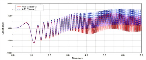
a) Change in the center of mass displacement
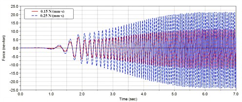
b) Change in damping force (the lower suspension point)
4. Conclusions
1) By establishing and analyzing the stiffness-flexibility coupling model of the washing machine, the dynamic responses of the flexible drum and suspension system can be effectively obtained. The results show that the increase of the spring stiffness coefficient will raise the system resonance frequency and reduce the damping effect, but a small stiffness may cause the outer drum to collide with the drum wall. The increase of the damping coefficient of the damper will not change the system’s natural frequency but can reduce the amplitude of resonance.
2) Using finite element software, the components can be discretized into small meshes for modal calculation, which can yield the modal neutral file, or MNF file, of the component. the MNF file contains the mass properties and modal characteristics of the target model. The mesh elements are connected by sharing a node to achieve force transmission. The internal stresses and strains of the component can be calculated based on the material properties. However, this calculation method uses modal superposition, so it can only simulate the linear deformation of the component.
References
-
P. R. Donavan and C. J. Janello, “Development of a recommended practice for evaluating rumble strip noise and vibration performance,” Transportation Research Record: Journal of the Transportation Research Board, Vol. 2678, No. 7, pp. 537–548, Dec. 2023, https://doi.org/10.1177/03611981231213567
-
C. Zhao and K. Chai, “Simulation study on the flow-induced vibration and noise in marine centrifugal pumps,” Journal of Vibration and Control, Vol. 30, No. 11-12, pp. 2549–2567, May 2023, https://doi.org/10.1177/10775463231180017
-
A. Ghorbel, B. Zghal, M. Abdennadher, L. Walha, and M. Haddar, “Investigation of friction-induced vibration in a disk brake model, including mode-coupling and gyroscopic mechanisms,” Proceedings of the Institution of Mechanical Engineers, Part D: Journal of Automobile Engineering, Vol. 234, No. 2-3, pp. 887–896, May 2019, https://doi.org/10.1177/0954407019845723
-
M. Sohrabifard, M. Nategh, and M. Ghazavi, “Evaluation, calibration, and modal analysis for determination of contact stiffness between workpiece and components of milling fixture,” Proceedings of the Institution of Mechanical Engineers, Part B: Journal of Engineering Manufacture, Vol. 237, No. 12, pp. 1819–1835, Nov. 2022, https://doi.org/10.1177/09544054221138165
-
F. Wang, W. Xu, L. Yan, and B. Liang, “Configuration reconstruction and all-joint synchronous measurement based on vision for segmented linkage manipulator of rigid-flexible dual-arm space robot,” Advances in Space Research, Vol. 74, No. 8, pp. 4009–4029, Oct. 2024, https://doi.org/10.1016/j.asr.2024.07.005
-
G. Y. Pan and Y. K. Feng, “Improved design of disc brake vibration based on spring contact dynamics model between disk and block,” Vibration and Shock, Vol. 41, No. 17, pp. 244–253, Sep. 2022, https://doi.org/10.13465/j.cnki.jvs.2022.17.030
About this article
The authors have not disclosed any funding.
The datasets generated during and/or analyzed during the current study are available from the corresponding author on reasonable request.
The authors declare that they have no conflict of interest.

