Abstract
The dynamic response characteristics of shock absorber have a crucial influence on the stability and safety performance of vehicles. Based on the finite element method, the modal simulation of the mechanical structure of shock absorber was conducted, and the natural frequencies and modal shapes were obtained. According to the dynamic stiffness test scheme, the first four natural frequencies were set as the excitation frequencies, and the response characteristics of displacement, damping force and dynamic stiffness were tested and analyzed. In the experimental loading scheme, shear force was applied to the damper, and the shear amplitude gradually increased from 0.5 mm. Three cycle tests were conducted to obtain the average evaluation value. The results show that although the natural frequencies of the mechanical structure of the shock absorber do not avoid the excitation frequency of the road surface, it still shows good dynamic response effects at low-order excitation frequencies. The elastic stiffness and damping stiffness of the shock absorber decrease with the increase of the shear amplitude, while the damping stiffness increases with the increase of the excitation frequency.
Highlights
- Based on the finite element method, the modal simulation of the mechanical structure of shock absorber was conducted, and the natural frequencies and modal shapes were obtained.
- According to the dynamic stiffness test scheme, the first four natural frequencies were set as the excitation frequencies, and the response characteristics of displacement, damping force and dynamic stiffness were tested and analyzed.
- In the experimental loading scheme, shear force was applied to the damper, and the shear amplitude gradually increased from 0.5 mm.
1. Introduction
The shock absorber in vehicles can improve the smoothness and comfort of driving, while ensuring the steering and braking functions of the vehicle to ensure driving safety [1, 2]. Shock absorber consume mechanical energy in the system by reducing vibration and shock, thereby protecting the mechanical system. Therefore, the modal characteristics have a significant impact on the damping effect [3-5]. Shock absorber usually adopt forms such as friction, liquid or gas resistance. Friction shock absorber prevent the movement of objects through the friction force between two contact surfaces. On the other hand, hydraulic shock absorber consume mechanical energy through the viscosity and resistance of the liquid to reduce vibration and shock [6]. Pneumatic shock absorber consume mechanical energy through gas resistance. According to their structure and function, shock absorber can be divided into various types, including friction shock absorber, hydraulic shock absorber, pneumatic shock absorber, hydraulic shock absorber, pneumatic shock absorbers and rotary shock absorbers. Currently, research mainly focuses on finite element analysis, dynamics research and modeling analysis, and relatively less attention is paid to the study of dynamic response, representative instances encompass: Li [7] put forward and fabricated a series of variable stiffness magnetic fluid shock absorbers, and carried out simulations and experimental tests on vibration attenuation under the circumstance of small amplitudes. Valerio [8] executed experimental and numerical evaluations of the impact behavior of a composite shock absorber to attain high mechanical efficiency of the shock absorber. In order to ensure the good performance of the shock absorber, it is proposed to use finite element analysis for modal calculation, and the influence of shear amplitude and excitation frequency on the elastic stiffness, damping stiffness and loss factor of the hydraulic shock absorber is studied using special test equipment. A deep understanding of these complexities can improve the design and performance in a wide range of applications from mechanical engineering to civil infrastructure. By exploring these complexities precisely and rigorously, engineers and researchers can open up new possibilities for optimizing damping systems in various fields.
2. Modal analysis of mechanical structure of shock absorber
2.1. The structure and working principle
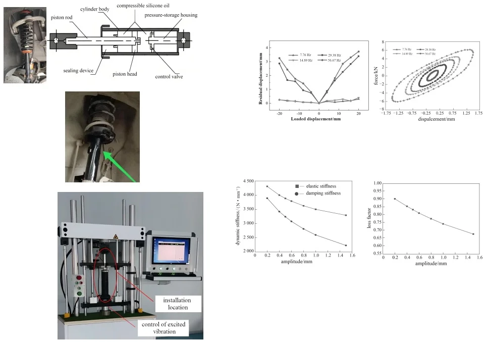
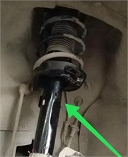
The main structure of the shock absorber for small carrier vehicles is shown in Fig. 1. The key mechanical components include the housing, damping elements and damping medium. This structure is relatively simple, but the rationality of the design will directly affect the usage effect. The external protective cover of the shock absorber is used to protect the internal components from the influence of the external environment. The internal damping elements include springs, rubber, air cushions, etc., which are responsible for absorbing the shock and vibration generated by the movement. The medium is usually made of oil, gas and friction pads, and is used to generate damping force to convert kinetic energy into heat energy. During the movement, the shock absorber, through the synergy of the damping elements and damping medium, converts the high-speed shock and vibration generated by the movement into heat energy to achieve the purpose of energy consumption. The working principles of different types of shock absorbers are also different. Firstly, the liquid is forced to pass through narrow channels to cause energy loss, and then flows to the piston inside the shock absorber column to form damping force and absorb the shock and vibration of the rod. The medium continuously presses the piston to generate greater damping force, and finally converts the kinetic energy of the rod into heat energy for consumption. The structure of the shock absorber is prone to large deformation or fatigue damage under long-term vibration, as shown in Fig. 2. Through modal analysis, verifying whether the mechanical structure of the shock absorber is reasonably designed has a crucial impact on the working stability of the suspension.
Fig. 1The main structure of the shock absorber
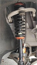
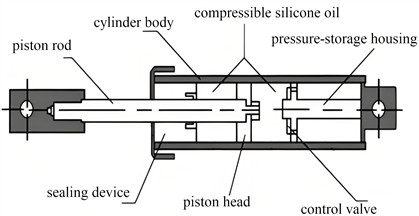
Fig. 2Large deformation caused by vibration
2.2. Simulation and calculation of modal characteristics
Modal analysis can be divided into free modal and constrained modal according to boundary conditions. Free modal analysis is mainly used to study the vibration characteristics of the structure in the unconstrained free state. The analysis of constrained modal is mainly used to study the vibration characteristics of the structure under the added external constraint conditions. The interaction attribute settings for the establishment of the finite element model are carried out in the finite element software for the contact problems among various structures. The types of settings are based on the mating relationship of each part of the shock absorber structure in reality. The connection methods between the cylinder and the base, and between the base and the installation support are welding. In finite element analysis, binding constraints are usually selected, such as the face-to-face contact between the piston rod and the guide seat, and between the piston valve system and the inner side of the hydraulic cylinder. Based on the relevant theory of modal analysis, the frequency analysis step under linear perturbation in ABAQUS is selected. Therefore, the first six effective modal shapes of the shock absorber can be obtained as shown in Fig. 3. The suspension system and shock absorbers will be subjected to many external excitations during the operation of the vehicle. The main ones include excitations from the road surface, excitations generated by wheel imbalance, and excitations produced by the engine, etc. Among them, the excitation frequency from the road surface is related to the roughness of the road surface, and the vibration frequency range is about 5 to 20 Hz. The excitation generated by wheel imbalance is generally less than 11 Hz. The first six natural frequencies are shown in Table 1. According to the natural frequency of the mechanical structure of this type of shock absorber, it can be known that the suspension system and the road surface complete the transmission of vibration through the wheels, which is prone to induce the occurrence of resonance phenomena. Therefore, it is necessary to further verify the responses of parameters such as load and displacement at the resonant frequency through testing methods to ensure the safety and reliability of the shock absorber structure.
Fig. 3The first four effective modal vibration shapes
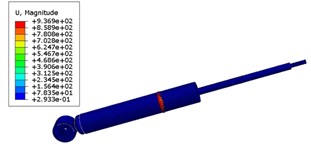
a) The firs order
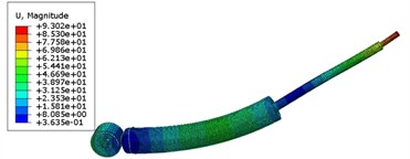
b) The second order
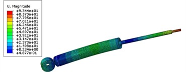
c) The third order
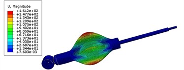
d) The fourth order
Table 1The first six natural frequencies
Order | 1 | 2 | 3 | 4 | 5 | 6 |
Natural frequency / Hz | 7.76 | 14.89 | 29.38 | 56.67 | 73.35 | 88.06 |
3. Test and analysis of excitation vibration response
3.1. Test scheme of excitation vibration
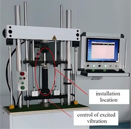
During the entire testing process, variations in the initial amplification angle, loading amplitude and loading frequency were adopted to apply loads to the supporting specimens, as shown in Fig. 4. A linkage device installed between the upper and lower fixtures of the testing machine can accommodate the placement of shock absorber, and a sinusoidal excitation waveform was selected. The actuator driven by the controller applies the test load to the shock absorber, and at the same time, the data of load, displacement, elastic stiffness, damping stiffness and loss factor of each specimen were collected during the test. Each test condition was repeated 10 times, and only the data of the last 3 cycles were recorded. Subsequently, the arithmetic average of these recorded values constitutes the final result. To ensure the dynamic test response in the vertical direction, the shock absorber is installed on the base plate of the support structure, connected to the working slider on the slide rail assembly by screws, and linked to a series of damping pads. The damping pads can prevent the errors caused by the rigid connection between the support structure and the slider. The criteria for data collection in the experiment is chosen as DIN 27201-2014, which includes the collection of displacement and force data, the calculation of equivalent stiffness, and the determination of the failure factor.
Fig. 4Test scheme of excitation vibration
3.2. The response of load and displacement
The excitation frequency is set to be the same as the natural frequency in the modal analysis results. The displacement characteristics under different excitation frequencies can be obtained as shown in Fig. 5. It can be seen that in the low-frequency state, the reset ability of the displacement is stronger, indicating a more effective energy absorption system at lower frequencies. In the lower frequency range, the stiffness curve of the energy absorption system forms an almost linear relationship with the load amplitude, demonstrating its stable and predictable behavior. With the increase of the load amplitude, the support stiffness continues to rise, resulting in the hysteresis curve gradually filling up. This phenomenon implies a significant increase in energy absorption capacity and enhanced structural elasticity. In addition, it should be noted that the stiffness of the shock absorber increases proportionally with the loading displacement without yielding. This indicates its robustness and the ability to withstand increasing forces while maintaining structural integrity. The displacement characteristics also show a certain compression at the origin position, resulting in a partial loss of the damping force transfer from the energy absorption system to the loading end. Understanding these complex dynamics is crucial for optimizing the performance of engineering applications involving such systems and ensuring safety.
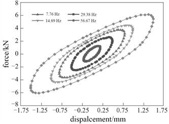
The damping force response under different frequencies is shown in Fig. 6. It can be seen that the area enclosed by the damping force curve before lubrication is very small. When the shear amplitude is 0.5 mm and the excitation frequency is 7.76 Hz, the area enclosed by the curve is 0.275 N·m. When the excitation frequency is increased to 29.38 Hz, the area enclosed by the curve is also only 0.305 N·m, indicating that the excitation frequency has little effect on the energy dissipation capacity of low-loss damping material. As the excitation frequency increases, the energy dissipated by the hydraulic damper in each vibration cycle gradually increases, significantly improving its energy dissipation capacity. Meanwhile, the slope of the load-displacement curve also gradually increases. As the excitation frequency increases, the pressure difference between the two oil chambers inside the damper increases, causing the pressure in the high-pressure oil chamber to rise. As the damping fluid experiences compressibility, the reduction in free volume within the fluid results in a notable increase in its viscosity. This heightened viscosity necessitates more energy for the dissipation of molecular chain segment migration and molecular chain sliding, contributing to enhanced damping performance. Moreover, with an escalation in shear frequency, there is a substantial rise in pressure loss due to contraction and expansion. Consequently, this amplifies the energy dissipation of the damper, further optimizing its effectiveness in managing vibrations and oscillations within mechanical systems.
Fig. 5The response of displacement
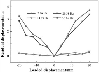
Fig. 6The response of damping force
3.3. The change of dynamic stiffness and damage factor
Dynamic stiffness refers to the ratio of the change in pressure to the change in displacement under a certain range of displacement and a certain frequency. Therefore, loading and unloading tests need to be conducted, and the dynamic response needs to be recorded and analyzed. The damage factor is a parameter that describes the phase difference between the deformation and stress of the shock absorber. Through the test, it can be concluded that the variation laws of dynamic stiffness and damage factor at the first-order natural frequency are shown in Fig. 7. When the amplitude increases to 1.5 mm, the elastic stiffness and damping stiffness of the shock absorber decrease by 23.6 % and 42.7 % respectively, which indicates that the elastic stiffness and damping stiffness of the shock absorber decrease with the increase of the shear amplitude. The internal structure of the vibration damper is a dual network of rubber and filler networks. At a small strain, the rubber material exhibits a high modulus due to the presence of a rigid filler network. With the increase of the strain, the reconstruction rate of the filler network cannot keep up with the damage rate, and the density of the filler network structure decreases. The modulus decreases, resulting in a decrease in the elastic stiffness of the shock absorber.
Fig. 7The variation laws of dynamic stiffness and damage factor
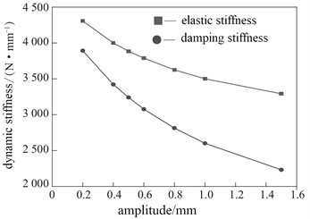
a) Change of dynamic stiffness
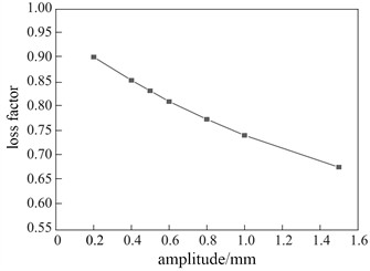
b) Change of damage factor
The stiffness of the shock absorber is one of the most critical factors in controlling the vibration and movement of mechanical systems. It plays a vital role in ensuring stability, safety, and performance. The damping effect of the damping fluid within the shock absorber is crucial for dissipating energy and reducing oscillations. When the damping fluid flows through the shock absorber, it encounters different flow velocities in different fluid layers. This leads to complex interactions among molecules when they move at different speeds in these layers. When the amplitude or shear stress on the damping fluid increases, its viscosity has a significant impact. Due to this increased stress, the long-chain molecules in the damping fluid start to migrate from different flow layers with different flow velocities to a common flow layer. Therefore, this phenomenon leads to shear thinning behavior, that is, at higher shear amplitudes, molecular chain segments continuously migrate out of their original positions. Due to this shear thinning behavior, the overall damping stiffness exhibited by the shock absorber significantly reduces when subjected to higher shear amplitudes. These complex dynamics provide valuable insights for optimizing the design and performance of shock absorbers in various engineering applications.
4. Conclusions
1) Under long-term and complex dynamic loading, shock absorbers are prone to failure, therefore, it is very necessary to analyze the causes of induced mechanical damage. By modal analysis, the natural frequencies and modes of the mechanical system can be identified, which can provide a basis for subsequent vibration characteristic analysis and structural dynamic property optimization design. In addition, by analyzing the test results of dynamic characteristics, the reasons for easy damage under different excitation frequencies and pressure loads can be inferred, which can provide a basis for improving reliability. It can be known that the low-order natural frequency of the mechanical structure of the shock absorber is within the excitation frequency range of the road surface, and the elastic deformation has a greater influence on the stiffness, which requires considering the influence of the damping fluid performance in the subsequent analysis and design.
2) The research on vibration response by combining the finite element simulation and dynamic performance test is an effective technical means. It is found that although the low-order natural frequencies of the mechanical structure do not completely avoid the external excitation range, the energy dissipation of the damping fluid provides important support for vibration reduction. With the increase of shear amplitude and frequency, the energy dissipation capacity of the damping device improves significantly.
References
-
N. Zhang, M. Fard, J. Xu, J. L. Davy, and S. R. Robinson, “Road safety: The influence of vibration frequency on driver drowsiness, reaction time, and driving performance,” Applied Ergonomics, Vol. 114, No. 1, p. 104148, Jan. 2024, https://doi.org/10.1016/j.apergo.2023.104148
-
A. F. Bezruchko, N. I. Zezetko, V. Vainola, W. Tanaś, and M. Szymanek, “Vibration reduction with rubber-metal cab supports,” Agricultural Engineering, Vol. 28, No. 1, pp. 1–8, Jan. 2024, https://doi.org/10.2478/agriceng-2024-0001
-
A. Daşdemir, “A modal analysis of forced vibration of a piezoelectric plate with initial stress by the finite-element simulation,” Mechanics of Composite Materials, Vol. 58, No. 1, pp. 69–80, Mar. 2022, https://doi.org/10.1007/s11029-022-10012-7
-
S. R. Jafari and M. Pasbani Khiavi, “Parametric study of the modal behavior of concrete gravity dam by using finite element method,” Civil Engineering Journal, Vol. 5, No. 12, pp. 2614–2625, Dec. 2019, https://doi.org/10.28991/cej-2019-03091437
-
X. Zhang et al., “Modal analysis and vibration control of a vertical cable with dual tuned mass dampers,” Journal of Low Frequency Noise, Vibration and Active Control, Vol. 43, No. 1, pp. 455–475, Jul. 2023, https://doi.org/10.1177/14613484231182487
-
M. Filippoupolitis and C. Hopkins, “Experimental validation of finite element models representing stacked concrete beams with unbonded surface contacts,” Engineering Structures, Vol. 227, No. 2, p. 111421, Jan. 2021, https://doi.org/10.1016/j.engstruct.2020.111421
-
Y. Li, D. Li, and Y. Li, “Performance tests and design of a series of magnetic fluid shock absorbers with varying stiffness based on optimal stiffness formula,” Frontiers in Materials, Vol. 9, No. 1, pp. 1–11, Oct. 2022, https://doi.org/10.3389/fmats.2022.1011550
-
V. Acanfora, M. Zarrelli, and A. Riccio, “Experimental and numerical assessment of the impact behaviour of a composite sandwich panel with a polymeric honeycomb core,” International Journal of Impact Engineering, Vol. 171, No. 1, p. 104392, Jan. 2023, https://doi.org/10.1016/j.ijimpeng.2022.104392
About this article
The authors have not disclosed any funding.
The datasets generated during and/or analyzed during the current study are available from the corresponding author on reasonable request.
The authors declare that they have no conflict of interest.
