Abstract
In order to improve the seismic resistance capacity of the multi-storey gymnasium frame, based on the finite element analysis method, the dynamic response characteristics were analyzed, and the natural frequencies and vibration modes were obtained. Based on the results of the modal analysis, different reinforcement methods were proposed for verification. Under the excitation conditions of Borego waves, the vibration responses of different nodes in initial model were obtained. Modal verification was carried out by using two methods of shear strengthening and support rod strengthening respectively. The analysis results show that the bearing capacity of the single-span frame is insufficient, the lateral stiffness is small, and it is prone to cause severe torsional vibration damage. It can also be known that the seismic resistance capacity of the support rods reinforcement is more balanced in different directions. It can not only effectively improve the lateral stiffness and bearing capacity of the structure, but also improve the seismic performance of the main structure through the energy dissipation of component yield, which is more suitable for multi-story buildings.
Highlights
- Based on the finite element analysis method, the dynamic response characteristics were analyzed, and the natural frequencies and vibration modes were obtained.
- Based on the results of the modal analysis, different reinforcement methods were proposed for verification.
- Modal verification was carried out by using two methods of shear strengthening and support rod strengthening respectively.
1. Introduction
Modal analysis is an effective technical means for studying the seismic performance of buildings [1, 2]. In the design process of multi-storey gymnasiums, it is indispensable to take into account the intricate and variable excitation loads and geological conditions, such as earthquakes and typhoons, which impose more rigorous challenges on the foundation and stability of the project [3, 4]. Traditional gymnasiums fall into the category of single-span frame structures, and their merits lie in relatively high construction efficiency and low cost. Nevertheless, during earthquakes, the structural safety redundancy is comparatively low, and the common failure mode is the loss of the bearing capacity of the load-bearing components due to local weak layers, which might lead to overall collapse in extreme cases. Under the influence of earthquakes, frame column components are damaged prior to frame beam components and generate concentrated plastic deformation. The seismic damage of the structure is mainly concentrated on the vertical load-bearing frame column components, while the damage degree of frame beam components is relatively low, and the weak layer centers on the frame columns [5]. Studies have indicated that the majority of house collapses in earthquake-stricken areas are attributed to the column hinge mechanism in the frame structure, resulting in house collapses and severe damage [6, 7]. In earthquake engineering, structural dynamic response can be analyzed by decomposing the modal shapes, which is of great significance for determining the peak acceleration and displacement response of the structure. In response to this issue, this paper conducts modal analysis on the initial structure to verify local high-risk structures and proposes reinforcement measures for verification to guarantee a significant enhancement in seismic performance.
2. Modal analysis of the initial frame structure
2.1. Establishment of the finite element model
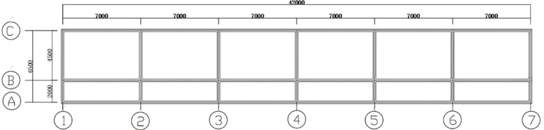
The multi-story gymnasium frame under study is a 3-story cast-in-place reinforced concrete single-span frame structure. The single-span is 7.0 m, the overhanging corridor is 2.0 m, and the floor height is 3.5 m for each story. The structural plan is shown in Fig. 1. The size of the frame column KZ1 is 500 mm×400 mm, the size of the transverse frame beam KL2 is 200 mm×700 mm, and the size of the coupling beam LL is 300 mm×500 mm. The concrete precast hollow floor slabs, beams and columns all adopt C30 concrete, and the main stressed reinforcement bars adopt HRB400 grade steel bars.
Fig. 1The plan structure and dimensions of the building
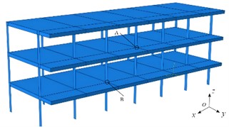
In ABAQUS, the plastic damage model (CDP) is used for the constitutive construction of concrete materials, and the shell element is used to model the floor, and the layered shell element is used to simulate the frame beam and column members. The reinforcement layer is modeled by layer, and the concrete is also equivalent to the corresponding layer. Finite element analysis requires the creation of two components, namely the wall and the roof, as shown in Fig. 2. Mainly considering the modal response analysis of the frame structure, the shapes of the door and window openings are irregular. During the modeling process, they are simplified, and the haunches at the ends of the beams are not considered. The wall and the roof are established as three-dimensional models by stretching according to the construction drawings. Considering the large degrees of freedom of the structure and the complex spatial load distribution, in order to improve the calculation accuracy and efficiency, the Lanczos method is adopted for modal solution. Lanczos method is a combination of inverse iteration method in vector space and Rayleigh-Ritz method. The original matrix variable eigenvalues are transformed into Ritz vector space, and then simplified to unit tridiagonal matrix eigenvalues. The specific steps of the Lanczos method are that the initial vector is processed several times, and then the orthogonal coefficients are transformed into a group of diagonal matrices, which are converted into the first several order eigensolutions of the original generalized matrix variable eigenvalues by certain transformation relations.
Fig. 2The three-dimensional model of the frame structure
2.2. Analysis of modal characteristics
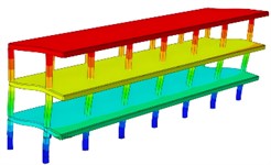
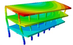
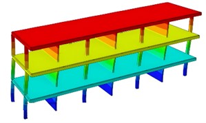
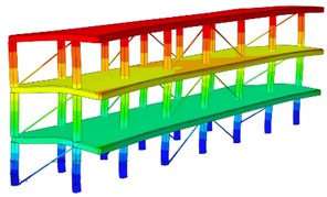
The calculation results of the first six natural frequencies are shown in Table 1. From the corresponding results of the vibration modes, as shown in Fig. 3, it can be seen that the vibration modes as a whole are manifested as vertical vibration, horizontal vibration and torsional vibration, all of which have strong symmetry and are closely related to the spatial symmetry of the structure. The first-order vibration mode is the coupled bending vibration of the entire structure in the horizontal and vertical directions. The 2nd to 4th order vibration modes are mainly vertical vibrations, among which the vibrations of the outer wall in the 2nd and 4th order vibration modes are the most obvious. The 3rd order vibration mode is mostly the vibration of the upper roof. The 5th order vibration mode is mainly vertical vibration at the top, accompanied by torsional vibration at the same time. The 6th order vibration modes all show vertical vibrations in the upper part, combined with horizontal vibrations. The vibration modes of the structure are mainly vertical vibrations, and the local part of the structure is accompanied by horizontal vibrations and torsional vibrations. It can be seen from the dynamic diagram that the low-frequency vibration of the structure is relatively serious, and the overall resonance balance is good under high-frequency conditions, indicating that the seismic characteristics of the structure can be improved by increasing the stiffness.
Table 1The first six natural frequencies
Order | 1 | 2 | 3 | 4 | 5 | 6 |
Nature frequency / Hz | 1.58 | 1.96 | 2.33 | 5.47 | 5.81 | 5.97 |
Fig. 3The first six-order modal vibration shapes
a) The firs order
b) The second order
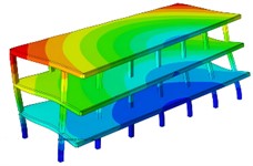
c) The third order

d) The fourth order
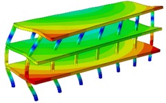
e) The fifth order
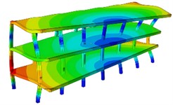
f) The sixth order
2.3. Response analysis of seismic waves
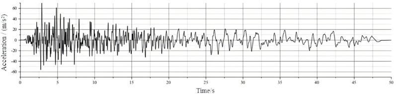
For the response analysis of seismic waves, the original seismic ground motion records cannot be directly used. According to the requirements of the specifications, seismic waves must meet three conditions, namely, consistent in statistical significance, meeting the requirements of base shear force and the requirements of seismic ground motion duration. The requirement of base shear force largely depends on the consistency in statistical significance. Therefore, the original seismic ground motion records should be processed before being used. Taking the seismic waves in southern California (Borrego wave) as an example, the seismic waves downloaded from the PEER seismic ground motion database need to be processed by seismic wave processing software to convert the selected original seismic ground motion format, including the adjustment of peak values and the calculation of spectral values. Finally, the available time history curve is obtained as shown in Fig. 4. The magnitude of acceleration represents the intensity of ground motion. The peak acceleration of ground motion can to some extent reflect the degree of influence of earthquakes on structures. It can effectively reflect the magnitude of the energy released by the ground motion and the influence on the deformation of the structure. Therefore, the peak acceleration of seismic waves should correspond to the peak required by the local fortification intensity.
Fig. 4The time-history curve of Borrego wave
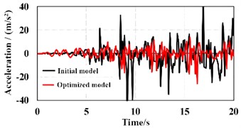
Through the time-history analysis method, the dynamic problems of the response spectrum method can be overcome. After determining the moment order, by using the step-by-step integration method, integration is carried out from the initial state until the earthquake action is completed. Finally, the dynamic seismic response of the entire system from the initial vibration to the completion of vibration during the entire process under the earthquake action can be obtained. Under the excitation condition of Borrego wave, the vibration response of node A and node B can be calculated as shown in Fig. 5. It can be seen that the amplitudes between different floors are relatively large, and optimization can be carried out through the reinforcement of the frame structure.
Fig. 5The vibration response of different nodes
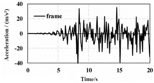
a) Node A
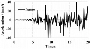
b) Node B
3. Optimization and verification of the structure
3.1. Reinforcement scheme of shear wall
To achieve the goal of efficient seismic resistance, while taking into account economy and construction convenience, a reinforcement scheme for shear walls is proposed. It is chosen to add reinforced concrete shear walls in the 2nd, 4th, and 6th spans, with a wall thickness of 240 mm, as shown in Fig. 6. The reinforced concrete shear walls are simulated using laminated shell elements.
Fig. 6The Reinforcement scheme of shear wall
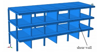
Fig. 7The first order modal vibration shape (4.63 Hz)
As shown in Fig. 7, through modal analysis, it can be known that adding shear walls in the direction of the structure increases the lateral stiffness of the structure, and the natural frequency has a significant improvement, making the structure less likely to be damaged first in this direction and achieving a good seismic effect. Since this single-span frame structure only adds shear walls in the direction for the convenience of construction and use after reinforcement, its -direction displacement is in a shear type. The horizontal displacement in the direction of the structure is comparable to the model. By adding shear walls, the lateral stiffness of the structure along the -axis is greatly increased, and the deformation of the single-span frame structure along the weak axis under earthquake action is reduced, with good lateral resistance performance. After adding shear walls only in the direction of the single-span frame, the -direction displacement has not decreased after calculation. For this situation, it may be because the out-of-plane stiffness of the shear wall is very small, and the seismic resistance in this direction leads to an insignificant reinforcement effect. Therefore, when adopting the seismic reinforcement scheme of shear walls, attention must be paid to the layout scheme of the shear walls. For a single structural system, when the structural stiffness increases, the structural lateral displacement and period will be reduced. Therefore, when increasing the structural stiffness, attention should be paid to the appropriate stiffness in the and directions. According to the response analysis of seismic waves, the vibration response of reinforcement scheme of shear wall can be obtained as shown in Fig. 8. It can be seen that compared with the initial structure, the maximum displacement of node A can be reduced by 62.2 %, and the maximum displacement of node B can be reduced by 51.3 % under the optimized shear wall scheme, showing a very obvious improvement in seismic resistance.
Fig. 8The vibration response of reinforcement scheme of shear wall
a) Node A
b) Node B
3.2. Reinforcement scheme of the supporting rods
In order to coordinate the deformation ratio, anti-buckling restraint support rods were arranged at different positions, as shown in Fig. 9. The structure is equipped with three buckling-restrained brace supports along the story height at the side span in the direction. Three pairs of buckling-restrained brace supports are respectively arranged along the story height at the middle beam span in the direction. This increases the lateral stiffness of the structure, making it less prone to damage and having good seismic performance.
Fig. 9Reinforcement scheme of the supporting rods
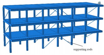
Fig. 10The first order modal shape (4.88 Hz)
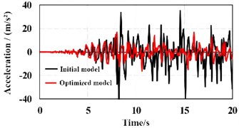
Through modal analysis, as shown in Fig. 10, the horizontal displacement in the direction of the structure was significantly reduced, achieving the expected purpose of increasing the stiffness in the direction and reducing the lateral displacement. Similarly, the maximum horizontal displacement in the direction of the structure was reduced by 18 %, increasing the lateral stiffness of the structure, reducing the deformation of the single-span frame structure under seismic action, and the lateral resistance performance was good. After adding buckling supports to the single-span frame structure, the lateral displacement of the structure did not reduce much, and the maximum inter-story drift angle of the structure was slightly smaller than before reinforcement. Considering the reinforcement cost and the convenience of use after reinforcement, during the reinforcement process using buckling supports, only three buckling-restrained supports were arranged along the floor height in the middle beam span in the direction, and three buckling-restrained supports were arranged along the floor height in the side span in the direction. According to the response analysis of seismic waves, the vibration response of reinforcement scheme of supporting rods can be obtained as shown in Fig. 11. It can be seen that compared with the initial structure, the maximum displacement of node A can be reduced by 66.5 %, and the maximum displacement of node B can be reduced by 62.2 % under the optimized shear wall scheme, showing a very obvious improvement in seismic resistance.
Fig. 11The vibration responses of reinforcement scheme of the supporting rods
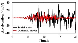
a) Node A
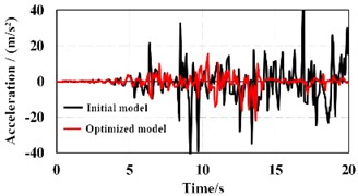
b) Node B
4. Conclusions
1) According to the analysis of the initial model, it can be known that the bearing capacity of the single-span frame is insufficient, the lateral stiffness is small, and the torsional seismic damage is severe. The inter-story drift angle of the single-span frame structure is too large, the lateral displacement is large, and the structure is prone to collapse, which is not conducive to the improvement of seismic resistance characteristics.
2) Through the modal analysis after reinforcement with buckling-restrained bracing rods and shear walls, it can be known that the buckling-restrained bracing rods are more conducive to the dispersion of vibration, reduce the deformation of the structure under seismic action, and improve the seismic performance of the structure. On the premise of ensuring convenient, fast construction, cost savings, and no impact on the use of the structure, the reinforcement scheme with buckling-restrained bracing rods can be given priority.
References
-
S. R. Jafari and M. Pasbani Khiavi, “Parametric study of the modal behavior of concrete gravity dam by using finite element method,” Civil Engineering Journal, Vol. 5, No. 12, pp. 2614–2625, Dec. 2019, https://doi.org/10.28991/cej-2019-03091437
-
M. Filippoupolitis and C. Hopkins, “Experimental validation of finite element models representing stacked concrete beams with unbonded surface contacts,” Engineering Structures, Vol. 227, No. 2, p. 111421, Jan. 2021, https://doi.org/10.1016/j.engstruct.2020.111421
-
A. Daşdemir, “A modal analysis of forced vibration of a piezoelectric plate with initial stress by the finite-element simulation,” Mechanics of Composite Materials, Vol. 58, No. 1, pp. 69–80, Mar. 2022, https://doi.org/10.1007/s11029-022-10012-7
-
J. Bergenudd, J.-M. Battini, and R. Crocetti, “Dynamic analysis of a pedestrian timber truss bridge at three construction stages,” Structures, Vol. 59, No. 1, p. 105763, Jan. 2024, https://doi.org/10.1016/j.istruc.2023.105763
-
A. Mena and Z. Volkmar, “Modal identification of structures with a dynamic behaviour characterised by global and local modes at close frequencies,” Acta Mechanica, Vol. 235, No. 3, pp. 1471–1491, May 2023, https://doi.org/0.1007/s00707-023-03598-z
-
J. Guo, G. Wei, X. Li, D. Jin, and F. Liu, “Modal identification of structures with closely spaced modes based on improved empirical wavelet transform,” Journal of Vibration Engineering and Technologies, Vol. 10, No. 7, pp. 2625–2640, Apr. 2022, https://doi.org/10.1007/s42417-022-00508-w
-
M. El Hoseny, J. Ma, and M. Josephine, “Effect of embedded basement stories on seismic response of low-rise building frames considering SSI via small shaking table tests,” Sustainability, Vol. 14, No. 3, p. 1275, Jan. 2022, https://doi.org/10.3390/su14031275
About this article

The authors have not disclosed any funding.
The datasets generated during and/or analyzed during the current study are available from the corresponding author on reasonable request.
The authors declare that they have no conflict of interest.
