Abstract
In order to evaluate ride performance of an electric vehicle (EV) active suspension systems (ASSs), a 8-DOF full-vehicle dynamic model of EV under random road excitation is set for control ASSs of EV to enhance ride comfort. A PID controller is proposed for control. The parameters of the PID controller are tuned using the Ziegler-Nichols method. The achieved results indicate that the root mean square (RMS) values of the vertical driver's seat, vehicle body, pitching and rolling acceleration responses with ASSs using the proposed controller respectively reduce by 31.12 %, 24.76 %, 15.00 %, and 11.59 % in comparison with passive suspension systems (PSSs) under the investigated condition. In addition, these results will be the basis for optimizing the parameters for PID controller to improve the ride performance of ASS.
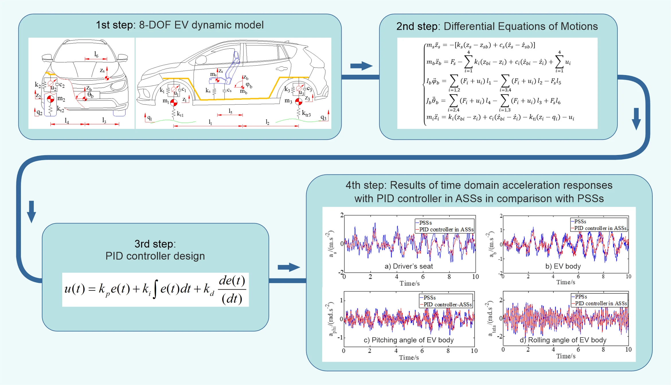
Highlights
- A 8-DOF full-vehicle dynamic model of EV under random road excitation is set for control ASSs of EV to enhance ride comfort.
- A PID controller is proposed for control. The parameters of the PID controller are tuned using the Ziegler-Nichols method.
- The root mean square (RMS) values of the acceleration responses with ASSs using the proposed controller respectively reduce in comparison with passive suspension systems (PSSs) under the investigated condition.
1. Introduction
Vehicle vibrations have a significant impact on the ride comfort and safety of electric vehicles (EVs). The suspension system is well-known for its critical role in absorbing these vibrations to enhance ride quality and vehicle safety. L. V. Quynh et al. [1] analyzed and compared the vibration suppression effectiveness for in-wheel motor, taking into account the motor suspension system. Unlike passive, semi-active, and active suspension systems (PSSs, S-ASSs, ASSs) offer greater flexibility to respond to unpredictable forces arising from road surface roughness and vehicle load, even while driving. To achieve this level of performance, various control algorithms have been applied to ASSs to ensure that the vehicle maintains optimal comfort and stability. For example, Maurya et al. [2] applied a LQR (Linear Quadratic Regulator) LQR controller for an ASS to enhance vehicle ride comfort and stability. While the LQR controller demonstrated improvements in vehicle performance, it had limitations, particularly in terms of robustness under varying conditions, and its performance could degraded when the model parameters change or are uncertain. Salem, et al. [3] proposed using a FLC (Fuzzy Logic Controller) for ASSs to suppress vibrations. However, the design of FLC demanded significant expertise and experience from the designer, as the performance heavily relies on the quality of the rule base and membership functions defined. Chen et al. [4] investigated the H∞ control strategy for ASSs. However, the complexity of designing an H∞ controller required a well-defined system model and could be computationally intensive, making it less practical for real-time applications. Kim et al. [5] analyzed the performance of an ASS using a SMC (Sliding Mode Controller), and the results showed significant improvements over PSSs. However, SMC was sensitive to system noise. Mehra et al. [6] introduced a new MPC (Model Predictive Control) design for ASSs. Nonetheless, it requires high computational power and a precise system model to predict future states accurately, which may not always be feasible in real-time vehicle applications. Van Thoan, T. et al. [7], [20] proposed PID controller for DWSPs (Driving Wheel Slip Prevention System) of a dump truck. Kumar et al. [8] presented a comparative study between PSSs and ASSs using a PID controller, demonstrating improved ride comfort and vehicle stability. In another study, Youness et al. [9] proposed a PID control strategy for an ASSs using a full vehicle model. The findings showed that the PID controller could effectively reduce vibrations and improve overall vehicle performance. For optimizing the functionality of the PID controller, various optimization algorithms and hybrid control strategies have been employed alongside the PID controller. For examples, Di Tan et al. [10] optimized the parameters of a PID controller for ASS using PSO (Particle Swarm Optimization), achieving improved system performance. Similarly, Boulaaras et al. [11] adjusted the proportional, integral, and derivative gains by implementing a GA (Genetic Algorithm), which reduced the workload for users and led to enhanced system quality. Xinjie et al. [12] researched a FLC around PID methodology for ASSs. However, using hybrid controllers or optimization algorithms remains a challenge. L. V. Quynh et al. [13] suggested a control strategy for damping on electric vehicle using a MSC (Modified Skyhook Controller). The flexibility of the suspension system was demonstrated by its effectiveness. In addition, several other control algorithms [14], [16-19] applied to control S-ASSs or semi-active mounting systems to improve their efficiency. In this study, The PID Controller is designed for EV ASSs to improve EV ride comfort via a full EV dynamic model.
2. EV dynamic model
2.1. Full EV dynamic model
A detailed 8-DOF (Degrees Of Freedom) EV dynamic model is employed to evaluate the ride performance of ASS, as illustrated in Fig. 1.
Fig. 18-DOF EV dynamic model
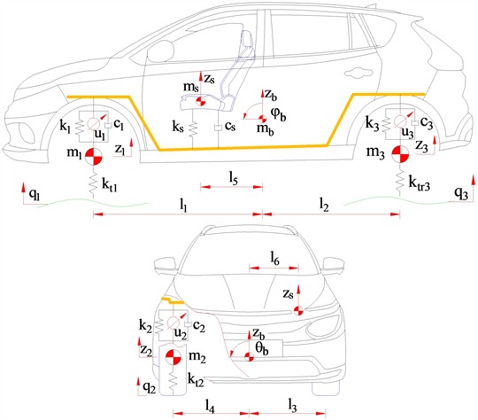
The vehicle model comprises the following parameters, , and are denoted by the masses of driver’s seat, EV body, and axle masses, respectively; and are denoted by the damping coefficients of driver’s seat PSS and EV PSSs, respectively; , and are denoted by the spring stiffness coefficients of driver’s seat PSS and EV PSSs, respectively; are denoted by the damping and stiffness coefficients of tires, respectively; are denoted by the suspension control signals from the actuator that generate the forces between the body and axles of EV; are the distances; and are denoted by the vertical displacement of EV axles and EV body, and are denoted by the angular displacements of EV body; qi aredenoted by the vertical displacement due to road surface excitations (1-4 and 1-6). Motion is frequently described using Jourdain’s principle [19] and the classic Newton-Euler method, Newton-Euler’s principle applied to the system results in the following differential equations of motion:
where, and are the inertia moments of EV body mass; and are the zero-bias points of EV body and driver’s seat which are determined by Eq. (2):
2.2. Road surface excitation
Accurate characterization of input signals is essential for evaluating how well the system performs in practical scenarios. Among the various types of input signals, white noise vibration is frequently selected by researchers for vibration analysis. This type of signal is particularly useful because it can simulate a wide range of disturbances and operational conditions. In this study, the time domain excitation of the road surface is selected to describe using the filtering white noise method [22] and the input signals of road surface excitation could be given by:
where, is denoted by the road surface lower frequency, is denoted by the road roughness coefficient, which is defined for typical road classes from to according to ISO 8068 [21], v is denoted by EV speed, is denoted by the reference frequency, and is denoted by Gaussian white noise.
3. PID controller design
The PID controller, one of the most common feedback controllers, works by continuously adjusting control efforts based on the error signal. The general PID control equation is:
where, is denoted by the control signal, is denoted by the error, and , , and are denoted by the proportional, integral, and derivative gains.
The input signal plays a crucial role in the controller efficiency. Therefore, in this study, the feedback signal is chosen as the relative displacements of ASSs, , serving as the input for the controller. The output consists of the controller’s parameters, including , , and . By selecting suspension displacement as the input, the system could effectively adjust to change, ensuring the optimal performance. Eq. (4) could be rewritten as follows:
To enhance control performance under survey operating condition, the Ziegler-Nichols approach has been used to determine the parameters of PID controller. The full EV dynamic model comprises with four suspensions, each requiring a dedicated PID controller. Despite the need for multiple controllers, their design process is analogous. Therefore, using the Ziegler-Nichols technique to optimize the proportional gains of the PID controller [23], [24], the controller parameters obtained are 41050, 3572, and 193.
4. Results and discussion
The ride performance of ASSs with the PID controller is investigated and compared PSSs when vehicle moves on road surface ISO class C at EV speed of 20 m/s and full load of EV. The parameters of the PID controller obtained after optimization which are used as input for the control signals of ASSs. Eq. (1) and the PID controller are simulated in Matlab/simulink environment with EV parameters in Table 1. The vertical driver’s seat, vehicle body, pitching and rolling acceleration responses (, , and ) with PID controller in ASSs in comparison with PSSs are shown in Fig. 2 when vehicle moves under the above survey condition.
Table 1EV parameters
Parameter | Value | Parameter | Value |
/ kg | 75 | , / N.m-1 | 22000 |
/ kg | 1380 | , / N.s.m-1 | 1000 |
, / kg | 60 | , / N.s.m-1 | 1040 |
, / kg | 65 | / m | 1.3 |
/ kg.m2 | 2280 | / m | 1.5 |
/ kg.m2 | 480 | / m | 0.84 |
/ N.m-1 | 50000 | / m | 0.84 |
/ N.m-1 | 1250 | / m | 0.32 |
, / N.m-1 | 17500 | / m | 0.56 |
The results in Fig. 2 show that the maximum amplitude values of , , and with PID controler in ASSs decrease very strongly compared to PSSs, which means that proposed controller for EV ASSs has significantly improved vehicle ride comfort. From the results of Fig. 2, , , and values are defined based on ISO 2631 (1997) [25] and , , and values with PID controller in ASSs in comparison with PSSs are shown in Table 2. The comparative results of Table 2 indicate that , , and values with PID controller ASSs respectively reduce by 31.12 %, 24.76 %, 15.00 %, and 11.59 % in comparison with PSSs under the above survey condition, which means that the proposed controller performance for EV ASSs significantly improves vehicle ride comfort compared to PSSs.
Table 2aws, awb, awphi and awteta values with PID controller ASSs in comparison with PSSs
/ (m/s2) | / (m/s2) | / (rad/s2) | / (rad/s2) | |
PID controller in ASS | 0.3657 | 0.3841 | 0.2459 | 0.6536 |
PSS | 0.5309 | 0.5105 | 0.2893 | 0.7393 |
Decrease % | 31.12 | 24.76 | 15.00 | 11.59 |
Fig. 2Results of time domain acceleration responses with PID controller in ASSs in comparison with PSSs
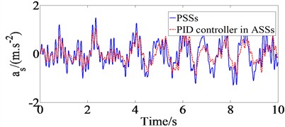
a) Driver’s seat
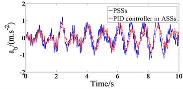
b) EV body
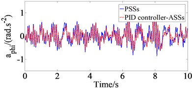
c) Pitching angle of EV body
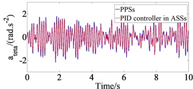
d) Rolling angle of EV body
5. Conclusions
In this study, a 8 -DOF full dynamic model of EV is proposed for control ASSs using PID controller towards enhancing ride comfort. The parameters of the PID controller are tuned using the Ziegler-Nichols method. The motion equations of EV and the combined PID controller are all implemented in the Matlab/Simulink software environment. The obtained results have shown that the maximum amplitude values of , , and with PID controller in ASSs decrease very strongly compared to PSSs when vehicle moves on road surface ISO class C at EV speed of 20 m/s and full load of EV. Finally, , , and values with PID controller ASSs respectively reduce by 31.12 %, 24.76 %, 15.00 %, and 11.59 % in comparison with PSSs under the above survey condition, which means that the proposed controller performance for EV ASSs significantly improves vehicle ride comfort compared to PSSs.
References
-
L. Quynh, B. Cuong, N. Liem, L. X. Long, and P. T. Thanh Dung, “Effect of in-wheel motor suspension system on electric vehicle ride comfort,” Vibroengineering Procedia, Vol. 29, pp. 148–152, Nov. 2019, https://doi.org/10.21595/vp.2019.21175
-
V. K. Maurya and N. S. Bhangal, “Optimal control of vehicle active suspension system,” Journal of Automation and Control Engineering, Vol. 6, No. 1, pp. 22–26, Jan. 2017, https://doi.org/10.18178/joace.6.1.22-26
-
M. M. M. Salem and Ayman A. Aly, “Fuzzy control of a quarter-car suspension system,” International Journal of Information Technology and Computer Engineering, Vol. 53, pp. 258–263, 2009.
-
Hong Chen and Kong-Hui Guo, “Constrained H/sub /spl infin// control of active suspensions: an LMI approach,” IEEE Transactions on Control Systems Technology, Vol. 13, No. 3, pp. 412–421, May 2005, https://doi.org/10.1109/tcst.2004.841661
-
C. Kim and P. I. Ro, “A sliding mode controller for vehicle active suspension systems with non-linearities,” Proceedings of the Institution of Mechanical Engineers, Part D: Journal of Automobile Engineering, Vol. 212, No. 2, pp. 79–92, Feb. 1998, https://doi.org/10.1243/0954407981525812
-
R. K. Mehra, J. N. Amin, K. J. Hedrick, C. Osorio, and S. Gopalasamy, “Active suspension using preview information and model predictive control,” in IEEE International Conference on Control Applications, pp. 860–865, Oct. 2024, https://doi.org/10.1109/cca.1997.627769
-
T. van Thoan et al., “An investigation in the control effectiveness of the driving wheel slip prevention system of a diesel engine dump truck,” SAE International Journal of Vehicle Dynamics, Stability, and NVH, Vol. 8, No. 3, pp. 311–327, May 2024, https://doi.org/10.4271/10-08-03-0017
-
Mouleeswaran Senthil Kumar, “Development of active suspension system for automobiles using PID controller,” in International Conference of Mechanical Engineering, 2008.
-
S. F. Youness and E. C. Lobusov, “Networked control for active suspension system,” Procedia Computer Science, Vol. 150, pp. 123–130, Jan. 2019, https://doi.org/10.1016/j.procs.2019.02.025
-
D. Tan, C. Lu, and X. Zhang, “Dual-loop PID control with PSO algorithm for the active suspension of the electric vehicle driven by in-wheel motor,” Journal of Vibroengineering, Vol. 18, No. 6, pp. 3915–3929, Sep. 2016, https://doi.org/10.21595/jve.2016.16689
-
Z. Boulaaras, A. Aouiche, and K. Chafaa, “PID controller optimized by using genetic algorithm for active suspension system of a quarter car,” in 19th International Multi-Conference on Systems, Signals and Devices (SSD), pp. 779–784, May 2022, https://doi.org/10.1109/ssd54932.2022.9955858
-
Ji Xinjie and Li Shengjin, “Design of the fuzzy-PID controller for new vehicle active suspension with electro-hydrostatic actuator,” in 2009 4th IEEE Conference on Industrial Electronics and Applications (ICIEA), pp. 3724–3727, May 2009, https://doi.org/10.1109/iciea.2009.5138898
-
L. Quynh, B. Cuong, H. A. Tan, and C. C. Huan, “Modified skyhook control for semi-active electric vehicle suspension,” in Lecture Notes in Networks and Systems, Vol. 602, Cham: Springer International Publishing, 2022, pp. 839–845, https://doi.org/10.1007/978-3-031-22200-9_88
-
H. A. Tan, P. van Thoan, N. D. Tan, V. T. Hien, and L. van Quynh, “Ride performance analysis of a semi-active hydraulic engine mounting system of a passenger car,” in Lecture Notes in Networks and Systems, Vol. 944, Cham: Springer Nature Switzerland, 2024, pp. 332–340, https://doi.org/10.1007/978-3-031-62235-9_33
-
N. T. Duy, L. van Quynh, D. V. Ha, B. van Cuong, and L. X. Long, “Ride comfort evaluation for a double-drum vibratory roller with semi-active hydraulic cab mount system,” in E3S Web of Conferences, Vol. 304, p. 01008, Sep. 2021, https://doi.org/10.1051/e3sconf/202130401008
-
L. van Quynh, D. V. Ha, B. van Cuong, L. A. Vu, and T. van Thoan, “Improvement of ride comfort quality for an earth-moving machinery with semi-active cab isolation system,” in E3S Web of Conferences, Vol. 304, p. 02012, Dec. 2021, https://doi.org/10.1051/e3sconf/202130402012
-
L. Quynh et al., “Analysis of dynamic wheel loads of a semi-trailer truck with air-spring and leaf – spring suspension systems,” ARPN Journal of Engineering and Applied Sciences, Vol. 15, No. 2, pp. 146–152, 2020.
-
L. Nguyen, Q. Le, and R. Jiao, “A modified technique for studying the automotive vibrations based on Jourdain’s principle,” Vibroengineering Procedia, Vol. 22, pp. 99–105, Mar. 2019, https://doi.org/10.21595/vp.2018.20458
-
N. V. Liem, Z. Jianrun, L. V. Quynh, and J. Renqiang, “Study of fuzzy control for cab’s isolation system of heavy truck,” Vibroengineering Procedia, Vol. 10, pp. 309–314, 2016.
-
T. Thoan et al., “A survey of efficiency of wheel slip prevention controlled for diesel engine truck under poor pavement conditions,” in Lecture Notes in Networks and Systems, Cham: Springer Nature Switzerland, 2024, pp. 150–158, https://doi.org/10.1007/978-3-031-62238-0_16
-
“Mechanical vibration-road surface profiles-reporting of measured data,” ISO 8068, International Organization for Standardization, 2016.
-
L. X. Long et al., “Study on the influence of bus suspension parameters on ride comfort,” Vibroengineering Procedia, Vol. 21, pp. 77–82, 2018.
-
E. Venkateswarulu, N. Ramesh Raju, and G. Seshadri, “The active suspension system with hydraulic actuator for half car model analysis and self-tuning with PID controllers,” International Journal of Research in Engineering and Technology, Vol. 3, No. 9, pp. 415–421, 2014.
-
Manoj Kushwah and Ashish Patra, “PID controller tuning using Ziegler-Nichols method for speed control of DC motor,” International Journal of Scientific Engineering and Technology Research, Vol. 3, No. 13, pp. 2924–2929, 2014.
-
“Mechanical vibration and shock-evaluation of human exposure to whole body vibration-part 1: general requirements,” ISO 2631-1, International Organization for Standardization, 1997.
Cited by
About this article
[Bui Van Cuong] was funded by the Master, Ph.D. Scholarship Program of Vingroup Innovation Foundation (VINIF), code [VINIF. 2023.TS.018].
The datasets generated during and/or analyzed during the current study are available from the corresponding author on reasonable request.
The authors declare that they have no conflict of interest.
