Abstract
In order to improve the dynamic response characteristics of the steering mechanism, a research scheme for increasing the natural frequency based on lightweight design was proposed. Based on the finite element method and the collaborative optimization method, the modal characteristics and harmonic response characteristics of the model were studied and analyzed to verify the strength and stiffness performance of the optimized structure. The modal shapes between the free mode and the constrained mode were compared and analyzed. With the second-order natural frequency as the optimization objective, the response surface function of the equivalent stiffness was constructed. Through optimization calculation, the design variables that satisfy the constraint conditions can be obtained. The results show that the optimized structure can increase the second-order natural frequency by 14.4 % on the premise of reducing the mass by 5.2 %, effectively avoiding the excitation frequency of the engine.
Highlights
- The modal characteristics and harmonic response characteristics of the model were studied and analyzed to verify the strength and stiffness performance of the optimized structure.
- The modal shapes between the free mode and the constrained mode were compared and analyzed.
- With the second-order natural frequency as the optimization objective, the response surface function of the equivalent stiffness was constructed.
1. Introduction
The main functions of the vehicle steering mechanism include supporting and transmitting loads. It can not only ensure the smooth operation of the vehicle, guide the vehicle to travel in a straight line or curve, but also can mitigate shock and vibration, ensure sufficient adhesion force and provide a good braking effect [1, 2]. As the vehicle steering mechanism is subject to the excitation vibration from the road surface and the engine for a long time, if the mechanical structure design is unreasonable, obvious vibration and noise are prone to occur. Therefore, the analysis of its dynamic characteristics and reliability optimization are very necessary, especially the analysis of modal properties [3, 4]. Due to the fact that the steering mechanism withstands the load similar to the harmonic excitation from the traction motor, it is crucial to conduct the harmonic response analysis of the bogie frame on the basis of the modal analysis to obtain the variation of its displacement with frequency [5]. Aiming at the problem that the natural frequency is close to the vibration frequency of the traction motor, the resonance interval is set, and the vibration reliability analysis of the steering mechanism is carried out to verify the vibration reliability of the structure [6]. Considering the uncertainty of deformation of the mechanical structure during operation, this paper proposes to conduct the stiffness reliability analysis of the steering mechanism. The multi-disciplinary reliability optimization design of the vehicle steering mechanism is carried out by using the collaborative optimization method combined with vibration reliability, static strength reliability and stiffness reliability, and the correctness of the optimization results is verified through simulation analysis.
2. Structural dynamic analysis
2.1. Modal analysis
Modal analysis can be divided into two types: free modal and constrained modal. Free modal refers to the modal analysis conducted when the bogie frame is not subject to any constraints, while constrained modal refers to the modal analysis conducted when the bogie frame is subject to constraints such as primary springs during the operation process. In this paper, the Block Lanczos method is used for modal analysis. This method has a fast calculation speed and high solution accuracy, and is suitable for large and complex models such as steering mechanisms.
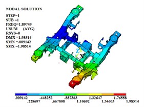
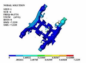
Fig. 1The first four effective free modal shapes
a) The firs order
b) The second order
c) The third order
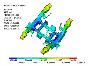
d) The fourth order
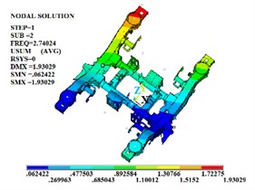
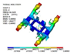
Fig. 2The first four constrained modal shapes
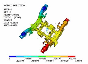
a) The firs order
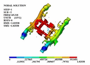
b) The second order
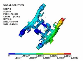
c) The third order
d) The fourth order
In the free modal analysis of the steering mechanism, since the frame is not subject to any constraints, its motion can consist of rigid body motions in three translational directions and three Rotational directions. These six rigid body motions are called the first six-order rigid body modes of the frame. The rigid body displacement has no period and the natural frequency is 0. Therefore, the values of the first six orders of modes are close to or equal to zero. After removing the first six-order rigid body modes, since most of the excitations in the actual operating environment are low-frequency excitations and the equivalent mass of the low-order modes is large and the participation coefficient is high, the first four-order modal shapes are shown in Fig. 1. In the actual line operation, the steering mechanism is mostly subject to various constraints in most cases to ensure that it does not produce excessive deformation during the operation process. Therefore, on the basis of the free modal analysis, it is necessary to conduct the constrained modal analysis of the steering frame. The first four-order modal shapes are shown in Fig. 2.
It can be known from the frequency values obtained through free modal and constrained modal analysis that the natural frequencies of the steering mechanism are significantly different. The vibration frequency values of each order of the framework under the constrained modal are all higher than those of each order of the framework under the free modal. The position of the maximum vibration amplitude of the structure also changes. Under the free modal, the part with the largest vibration amplitude is the axle box spring seat. Under the constrained modal, the position with the largest vibration amplitude is at the connection between the side beam and the crossbeam. When the external excitation is close to each order frequency, the steering mechanism is prone to resonance phenomenon.
2.2. Harmonic response analysis
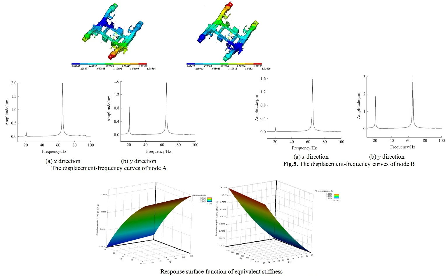
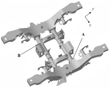
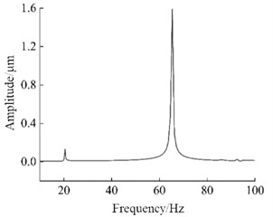
In the harmonic response analysis, more attention needs to be paid to the corresponding relationship between the response and the frequency, rather than the definite response amplitude. Therefore, the longitudinal and vertical harmonic excitation amplitudes can be set as 1000 N, the longitudinal harmonic excitation lags the vertical harmonic excitation by a phase angle of 90 degrees, and the frequency extraction range is 10 Hz-100 Hz. The selected node positions are shown in Fig. 3 and the harmonic response analysis results of the corresponding node are shown in Fig. 4 and Fig. 5.
Fig. 3Nodes for harmonic response calculation
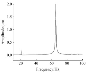
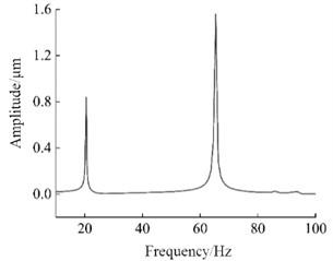
Through the harmonic response analysis of the selected nodes, it can be seen that in the frequency range of 10 Hz-100 Hz, when the first longitudinal displacement peak occurs, the excitation frequency is 43.03 Hz, and the corresponding excitation frequency range is 19 Hz-21 Hz. This indicates that within this frequency range, the excitation frequency excites the first-order natural frequency of the steering mechanism, the structure undergoes resonance and a large deformation phenomenon occurs, and the displacement of the selected nodes reaches the peak. Similarly, when the second displacement peak occurs, the excitation frequency is 65.22 Hz, within the excitation frequency range of 64 Hz-66 Hz, the excitation frequency excites the second-order natural frequency of the steering mechanism, resulting in another peak in the longitudinal displacement of the selected nodes. The peak displacements of the selected nodes in different. The peak displacements of the selected node in different directions have both excited the first and second-order natural directions both excited the first and second natural frequencies of frequencies of the structure, resulting in structural resonance of the steering mechanism. Meanwhile, it also verifies the structure, resulting in structural resonance of the steering the accuracy of the modal calculation and analysis of the mechanism. At the same time, the accuracy of steering mechanism. The research results also show that the modal calculation and analysis of the steering mechanism was vertical displacement of the steering mechanism is larger than the also verified. The research results also show that the longitudinal displacement. When the excitation frequency is close to the natural frequency of the structure, deformation occurs. vertical displacement of the steering mechanism is larger than the harmonic response analysis can provide a reference for the longitudinal displacement. When the excitation frequency is close to vibration performance design of the structure. In the design the natural frequency of the structure, the structure undergoes process, the relationship between the natural frequency of the deformation. The harmonic response analysis can provide a reference structure, and the external excitation frequency should be fully considered for the vibration performance design of the structure. In order to avoid resonance of the structure, which may lead to insufficient or damaged structural performance.
Fig. 4The displacement-frequency curves of node A
a) direction
b) direction
Fig. 5The displacement-frequency curves of node B
a) direction
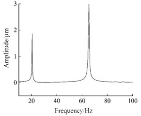
b) direction
3. Collaborative optimization
3.1. The establishment of the optimization model
In order to fully optimize the steering mechanism, avoid a large amount of calculation and reduce unnecessary waste of resources, the sensitivity analysis of the design variables is carried out to screen out the factors that have a greater impact on the natural frequency of the steering mechanism. The Design of Experiments module of the Workbench software is selected for sensitivity analysis, and the Latin Hypercube method is used to sample the design variables to obtain the four design variables with the maximum sensitivity. Sensitivity is essentially the derivative of the response surface function with respect to the optimized variable, which is numerically equal to the slope of the response trend curve, with positive or negative indicating an increase or decrease. In order to fully reflect the comparability of different design variables, relative sensitivity, which is expressed in percentage form, was adopted. Sensitivity analysis can effectively screen the types of design variables.
Fig. 6Selection of design variables
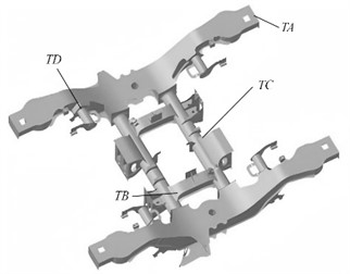
Fig. 7Sensitivity of the design variable
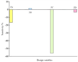
The structures of the selected design variables and the sensitivity analysis histogram are shown in Fig. 6 and Fig. 7 respectively. It can be known from the results of the sensitivity analysis that different design variables have different degrees of influence on the second-order natural frequency of the steering mechanism.
For the structural optimization of steering mechanisms, response surface fitting and target extremum solving techniques can be adopted and applied. The accuracy of response surface fitting determines the accuracy of the reliability analysis results. Therefore, 20 sample data were randomly selected, and the true values and predicted values of this sample were compared. The multiple correlation coefficient of the fitting accuracy of the response surface function was obtained as 99.91 %. The optimization of the steering mechanism aims at reducing costs and increasing efficiency. Therefore, it is necessary to incorporate mass and stress peaks into the constraint conditions. Without increasing the quality and stress peaks, by matching and coordinating the structure, the natural frequency can be increased, thereby balancing the reliability indicators of each discipline and meeting the requirements of lightweight design. Among the commonly used multidisciplinary optimization methods, the collaborative optimization method has an easy-to-understand logical structure, strong engineering applicability, and high computing efficiency. Therefore, the collaborative optimization method was adopted, and the equivalent stiffness was taken as the optimization objective.
3.2. Analysis and discussion of the optimization results
In the multidisciplinary optimization design platform, the reliability optimization design process of the steering mechanism is established, including one system-level calculation module and three subsystem-level calculation modules. The system-level calculation module is composed of an optimization component, three subsystems in parallel and a calculator component in series. The solution method of both the system-level and subsystem-level calculation modules adopts the sequential quadratic programming method (NLPQL). The variation range of the system-level optimization variables is taken as ±30 % of the initial design, and the best optimization scheme is sought through iteration. Through approximate fitting, the response surface function of the equivalent stiffness can be obtained as shown in Fig. 8.
To ensure the global optimal solution, the mass optimization objective can be transformed into boundary conditions. Through the target extremum search method, the design variables that satisfy the boundary conditions and optimization goals can be obtained. The second-order natural frequency and stress peak of the verification model are shown in Fig. 9. According to the optimization results, it can be known that the second-order natural frequency of the improved structure is 74.62 Hz, which has increased by 14.4 % and effectively avoids the excitation frequency of the engine. Compared to the initial value, the equivalent stiffness has increased by 13.8 %, the mass has decreased by 5.2 %, and the maximum stress is less than the yield limit, meeting the strength requirements.
Fig. 8Response surface function of equivalent stiffness
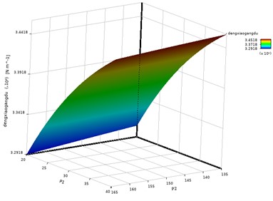
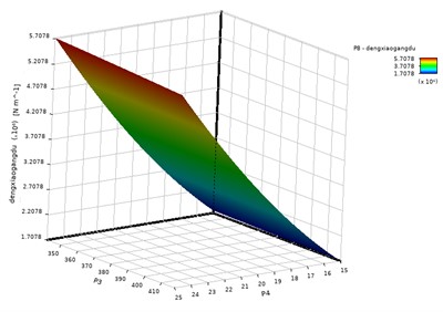
Fig. 9The verification of the optimized results
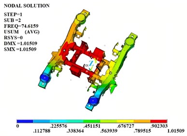
a) The second-order modal shape
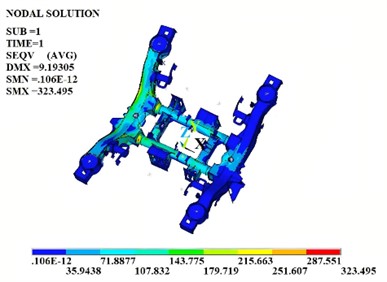
b) Stress distribution characteristics
4. Conclusions
1) On the basis of modal analysis, the harmonic response analysis is carried out to calculate the displacement-frequency variation curve of the vibration amplitude at each key point of the steering mechanism with the excitation frequency, and the possible frequency range of resonance is obtained, laying the foundation for the subsequent vibration reliability analysis and optimization design.
2) The research on vibration response by combining the finite element simulation and dynamic performance test is an effective technical means. It is found that although the low-order natural frequencies of the mechanical structure do not completely avoid the external excitation range, the energy dissipation of the damping fluid provides important support for vibration reduction. With the increase of shear amplitude and frequency, the energy dissipation capacity of the damping device improves significantly
References
-
C. Yang, “Strain modal response and vibration damping optimization of tower for wind power equipment,” Journal of Vibroengineering, Vol. 26, No. 5, pp. 1166–1179, Aug. 2024, https://doi.org/10.21595/jve.2024.23952
-
Q. Lin, C. Yang, Y. Bai, and J. Qin, “Structural strength analysis and optimization of commercial aircraft nose landing gear under towing taxi-out conditions using finite element simulation and modal testing,” Aerospace, Vol. 11, No. 5, p. 414, May 2024, https://doi.org/10.3390/aerospace11050414
-
Z. G. Wang, “Structural optimization and modal analysis of belt conveyor driving drum,” Journal of Engineering Mechanics and Machinery, Vol. 9, No. 1, pp. 74–88, Jan. 2024, https://doi.org/10.23977/jemm.2024.090113
-
S. R. Jafari and M. Pasbani Khiavi, “Parametric study of the modal behavior of concrete gravity dam by using finite element method,” Civil Engineering Journal, Vol. 5, No. 12, pp. 2614–2625, Dec. 2019, https://doi.org/10.28991/cej-2019-03091437
-
M. Filippoupolitis and C. Hopkins, “Experimental validation of finite element models representing stacked concrete beams with unbonded surface contacts,” Engineering Structures, Vol. 227, No. 2, p. 111421, Jan. 2021, https://doi.org/10.1016/j.engstruct.2020.111421
-
A. Daşdemir, “A modal analysis of forced vibration of a piezoelectric plate with initial stress by the finite-element simulation,” Mechanics of Composite Materials, Vol. 58, No. 1, pp. 69–80, Mar. 2022, https://doi.org/10.1007/s11029-022-10012-7
About this article

The authors have not disclosed any funding.
The datasets generated during and/or analyzed during the current study are available from the corresponding author on reasonable request.
The authors declare that they have no conflict of interest.
