Abstract
In response to improve the quality and level of hydrostatic transmission (HST) products for modern mobile machineries, the closed-loop transfer functions of a HST are established by mathematical modeling, a comprehensive testing equipment is developed employing a proportional relief valve for automatic program loading and fuzzy-PID oil temperature control, the testing equipment is capable of conducting various performance tests for various models of HST integrated pump-motor products, including factory and type tests, especially continuous impact and endurance performance tests under high temperature and high-speed conditions. Comprehensive performance test of the above test sample is carried out using the developed equipment, that the test results agree well with the previous simulation results verifies the correctness of the established theoretical analysis model. The obtained theory and equipment from this work provide theoretical and experimental technical support for improving design and development of high-end fluid components for modern mobile machinery HST.
Highlights
- A comprehensive testing equipment is developed
- The testing equipment can conduct performance tests for various models of HST integrated pump-motor products
- The test results verify the correctness of the established theoretical analysis model
- Comprehensive response and stability of the fluid power control system
1. Introduction
Hydrostatic transmission systems (HST) are widely used in the moving or steering drive of mobile machineries [1-3] for their compact structure, high energy density and volumetric efficiency, as well as their ability to provide continuous variable speed transmission, thus, the study of HST characteristics and comprehensive testing technology is of significance for improving the quality and level of the HST system.
In previous studies, Cheng et al. [4] studied the speed control technology of HST under load disturbance, Bhola et al. [5] designed a new type of dual-pump drive motor system in HST, removing the traditional oil charge pump and relief valve and making the system more energy-saving and more adaptable to load. In the test technology of the integrated pump-motor, Xu et al. [6] designed a comprehensive test stand for HST using a hydraulic motor for loading, Zhao [7] designed and simulated the energy recovery plan in HST testing process, Kumar et al. [8] studied the sensor-based monitoring technology of the HST system. In addition, in the research on similar [9-10] transmission systems based on HST technology, the impact of the characteristics of the integrated pump-motor on system performance was studied.
In this study, mathematical modelling of the fluid power control of HST used in an agricultural machinery is firstly performed, then a test rig was developed for comprehensive testing of general HST products and experiments were conducted to studying the characteristics of the agricultural machinery HST. Result comparison and analysis was finally carried out, aiming to provide theoretical and experimental technology support for improving the quality and level of HST products for modern mobile machineries.
2. Modelling the fluid power control of HST
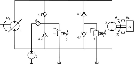
Figure 1 shows the hydraulic circuit of a HST used in an agricultural machinery. Essentially, the HST is a compact closed-loop speed control circuit, where a bidirectional variable pump 1 directly drives a bidirectional fixed-displacement hydraulic motor 2 to rotate. When there is a significant change in the host machine load, such as during deceleration or braking operations, it will lead to high pressure at the discharge port of the motor, at this time, the high-pressure relief valve 3 will open. The charge pump 7 is a low-pressure pump which compensates oil to the close-loop circuit, and its maximum working pressure is set by the low-pressure relief valve 5. In addition, the check valves 4 would control the right directions of the oil in different situations.
Fig. 1Hydrostatic transmission used in an agricultural machinery: 1. Variable hydraulic pump, 2. Hydraulic motor, 3. High-pressure relief valve, 4. Check valves, 5. Low-pressure relief valve, 6. Oil filter, 7. Charge pump
The flow-pressure characteristics, flow continuity and force equilibrium equations of the displacement variable mechanism of the variable pump in Fig. 1 are respectively formulated by:
Thus, performing Laplace Transform of Eqs. (1)-(3) to obtain:
With Eqs. (4)-(6) and neglect and , the actuation displacement of the variable mechanism could be formulated by:
Thus, the transfer functions of actuation displacement of the variable mechanism to its load disturbance force or to valve spool displacement can be deduced as:
In addition, the transfer functions of rotation angle of the hydraulic motor in Fig. 1 to inclination angle of swash plate of the variable pump or to load torque of the HST can similarly be deduced as:
Therefore, with the above mathematical modelling, the close-loop control block diagram of the HST can be obtained, as demonstrated by Fig. 2.
Fig. 2Close-loop control block diagram of the HST
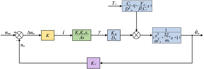
Thus, referring to Fig. 2, the closed-loop transfer functions of the hydraulic motor's output angular velocity to its rotational speed command or to its load disturbance can be respectively derived as:
The mathematical model established above has described the systematic transfer characteristics of the HST, especially that from the actual load to the drive speed of a agricultural machinery.
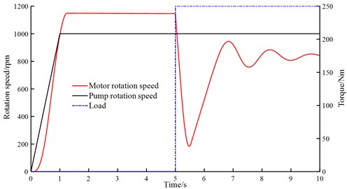
Fig. 3 demonstrates the comprehensive response and stability performance of the above fluid power control system and shows that in the first unloaded 5 seconds the motor rotation speed responds rapidly and stabilizes in the desired value, when a step load of 250 Nm is added at the fifth seconds, the motor rotation speed also responds quickly and stabilizes in an optimum value by close-loop control of the HST system. Thus, the above HST control system has obtained good response and stability characteristics.
Fig. 3Comprehensive response and stability of the fluid power control system
3. Test rig development and experiment
A comprehensive testing equipment is developed employing a proportional relief valve for automatic program loading and fuzzy-PID [11] oil temperature control, as shown in Fig. 4(a), the testing equipment is capable of conducting various performance tests for various models of HST integrated pump-motor products, including factory and type tests, especially continuous impact and endurance performance tests under high temperature and high-speed conditions.
Using the above self-developed new comprehensive test system, comprehensive performance tests were conducted on the HST product that was previously modeled and simulated. The installation of the test piece on the test rig and detailed oil port connection instructions are shown in Fig. 4(b).
Fig. 4Test rig development and experiment of a HST product
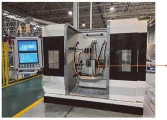
a) The developed comprehensive test rig for HST
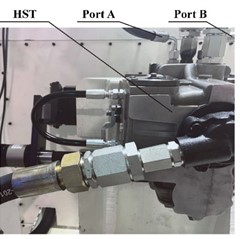
b) A HST product is under testing
4. Result and discussion
Fig. 5 compares some of the test and simulation results of the hydraulic motor in the HST. Fig. 5(a) shows that the simulation results are generally ahead of the test results, and the leading effect is more obvious in the high-pressure, high-speed area. This is due to the fact that the actual response lag of hydraulic components is often greater than the predicted values of theoretical models. However, the maximum relative error of the simulation results is less than 7.6 %, thus, the accuracy of the theoretical simulation model established earlier has been verified. Fig. 5(b) demonstrates that the hydraulic motor exhibits overshoots both at the start of operation and when the relief valve begins to relieve. When the relief process is finally completed, the rotation speed drops rapidly, and then quickly recovers as the relief valve is closed. The simulation results are in good agreement with the test results.
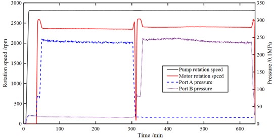
Fig. 6 demonstrates the dynamic performance of the HST during an endurance test, the test is carried out when the hydraulic pump is operated at its maximum swing angles both in the positive and negative directions, and with a rotation speed of 2800 rpm, a pressure varying from 25 to 28 MPa. The pump is run for 5 hours in each direction. Fig. 6 indicates that both of the pump and motor in the HST perform well and steadily during the whole test, the comprehensive test results after the endurance test also show that the test sample has obtained good endurance characteristics.
Fig. 5A comparison of test and simulation results of the hydraulic motor performance in the HST
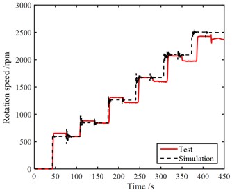
a) Break-in characteristics
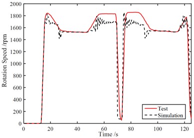
b) When the high-pressure relief valve relieves
Fig. 6Dynamic performance of the HST during an endurance test
5. Conclusions
1) The closed-loop transfer functions for fluid power control of a HST used in a modern agricultural machinery was established through mathematical modeling. A comprehensive performance testing equipment for various types of HST products has been designed and developed. By employing a proportional relief valve for automatic program loading and fuzzy-PID oil temperature control, the developed equipment is capable of conducting comprehensive performance tests, including factory and type tests, especially continuous impact and endurance performance tests under high temperature and high-speed conditions.
2) Using the developed testing equipment, a comprehensive performance test was conducted on the aforementioned HST integrated pump-motor. Comparing and analyzing the test results with the theory-based simulation results showed that there is a good match between the simulation and test results, with the maximum relative error being 8.9 %, thereby verifying the correctness of the established theoretical model.
3) The theoretical model and testing equipment obtained from this work would provide theoretical and experimental technical support for improving the quality and level of core fluid components for modern agricultural machinery HST.
References
-
W. Wu, J. Luo, C. Wei, H. Liu, and S. Yuan, “Design and control of a hydro-mechanical transmission for all-terrain vehicle,” Mechanism and Machine Theory, Vol. 154, p. 104052, Dec. 2020, https://doi.org/10.1016/j.mechmachtheory.2020.104052
-
H. X. Wang, K. J. Zang, X. D. Liu, and L. Xing, “Research on the development of HST drive technology in corn harvester,” (in Chinese), Journal of Jiamusi University (Natural Science Edition), Vol. 36, No. 6, pp. 914–916, 2018, https://doi.org/10.3969/j.issn.1008-1402(2018)06-0914-03
-
X. Ma, Y. M. Li, Z. Tang, J. Huang, and L. H. Zhu, “Structural features and developing tendency of the steering mechanism for the crawler combine harvester,” (in Chinese), Journal of Agricultural Mechanization Research, Vol. 40, No. 4, pp. 1–6, 2018, https://doi.org/10.3969/j.issn.1003-188x(2018)04-0001-06
-
Z. Cheng and Z. Lu, “Research on load disturbance based variable speed PID control and a novel denoising method based effect evaluation of HST for agricultural machinery,” Agriculture, Vol. 11, No. 10, p. 960, Oct. 2021, https://doi.org/10.3390/agriculture11100960
-
M. Bhola, T. O. Andersen, and M. K. Ebbesen, “Design of novel closed-circuit hydrostatic transmission without charge pump,” in ASME/BATH 2023 Symposium on Fluid Power and Motion Control, Oct. 2023, https://doi.org/10.1115/fpmc2023-111738
-
C. Xu, J. Xie, J. Wu, D. Sun, J. Mi, and Z. Liu, “Design of a comprehensive test bench for hydrostatic transmission,” Instrumentation Mesure Métrologie, Vol. 18, No. 1, pp. 81–92, Mar. 2018, https://doi.org/10.3166/i2m.17.81-92
-
H. Zhao, “Development of a hydraulic pump motor test stand based on mechanical power recovery,” Applied Mathematics and Nonlinear Sciences, Vol. 9, No. 1, pp. 1–17, Jan. 2024, https://doi.org/10.2478/amns.2023.2.00147
-
N. Kumar, R. Kumar, B. K. Sarkar, and S. Maity, “Condition monitoring of hydraulic transmission system with variable displacement axial piston pump and fixed displacement motor,” Materials Today: Proceedings, Vol. 46, pp. 9758–9765, Jan. 2021, https://doi.org/10.1016/j.matpr.2020.09.327
-
S. Xiong, G. Wilfong, and J. Lumkes, “Components sizing and performance analysis of hydro-mechanical power split transmission applied to a wheel loader,” Energies, Vol. 12, No. 9, p. 1613, Apr. 2019, https://doi.org/10.3390/en12091613
-
G. Xia, H. Zong, X. Tang, L. Zhao, and B. Sun, “Integrated control strategy of tractor hydromechanical continuously variable transmission,” Proceedings of the Institution of Mechanical Engineers, Part D: Journal of Automobile Engineering, Vol. 235, No. 2-3, pp. 649–671, Sep. 2020, https://doi.org/10.1177/0954407020951148
-
B. Xu, F. Sun, Y. Pan, and B. Chen, “Disturbance observer based composite learning fuzzy control of nonlinear systems with unknown dead zone,” IEEE Transactions on Systems, Man, and Cybernetics: Systems, Vol. 47, No. 8, pp. 1854–1862, Aug. 2017, https://doi.org/10.1109/tsmc.2016.2562502
-
X. Hu, M. X. Lin, and X. Dong, “Development of comprehensive performance testing system for hydraulic components based on LabVIEW,” (in Chinese), Machine Tool and Hydraulics, Vol. 48, No. 8, pp. 117–122, 2020, https://doi.org/10.3969/j.issn.1001-3881.2020.08.027
About this article

The authors have not disclosed any funding.
The datasets generated during and/or analyzed during the current study are available from the corresponding author on reasonable request.
The authors declare that they have no conflict of interest.
