Abstract
To clarify the motion characteristic of the drill string in deviated well, the nonlinear dynamic model of lateral-torsional coupling for drill string system is established by the Lagrange equation. This model incorporates the contact between the drill string and borehole wall, torque dissipation, and borehole trajectory effects. Additionally, the contact behavior using linear elastic contact model is simulated. Meanwhile, the torque transfer law in the drill string system is described by a discrete torque-drag model. Finally, numerical simulations are employed to determine the dynamic properties of the drill string system. The results reveal that friction losses in drill string systems are increased with higher well inclination angles. The motion of BHA along the direction is predominantly concentrated near the wellhole center at inclination angle of 65°, while in the direction it primarily focuses on the low side of the wellhole. An increase in inclination angle leads to a more prominent occurrence of stick-slip motion in the drill string. When inclination angle more than 25°, there is a slightly higher collision frequency observed between the BHA and the low side of the borehole wall compared to that with the upper side. When increasing the WOB (weight on bit) to 160 kN, stick-slip motion becomes more pronounced within the drill string. Through parametric dynamics analysis of the drill string system, the rotary speed can be controlled in range from 40 to 70 r/min, and the WOB should be restricted in range from 20 to 40 kN in well depth 5000 m.
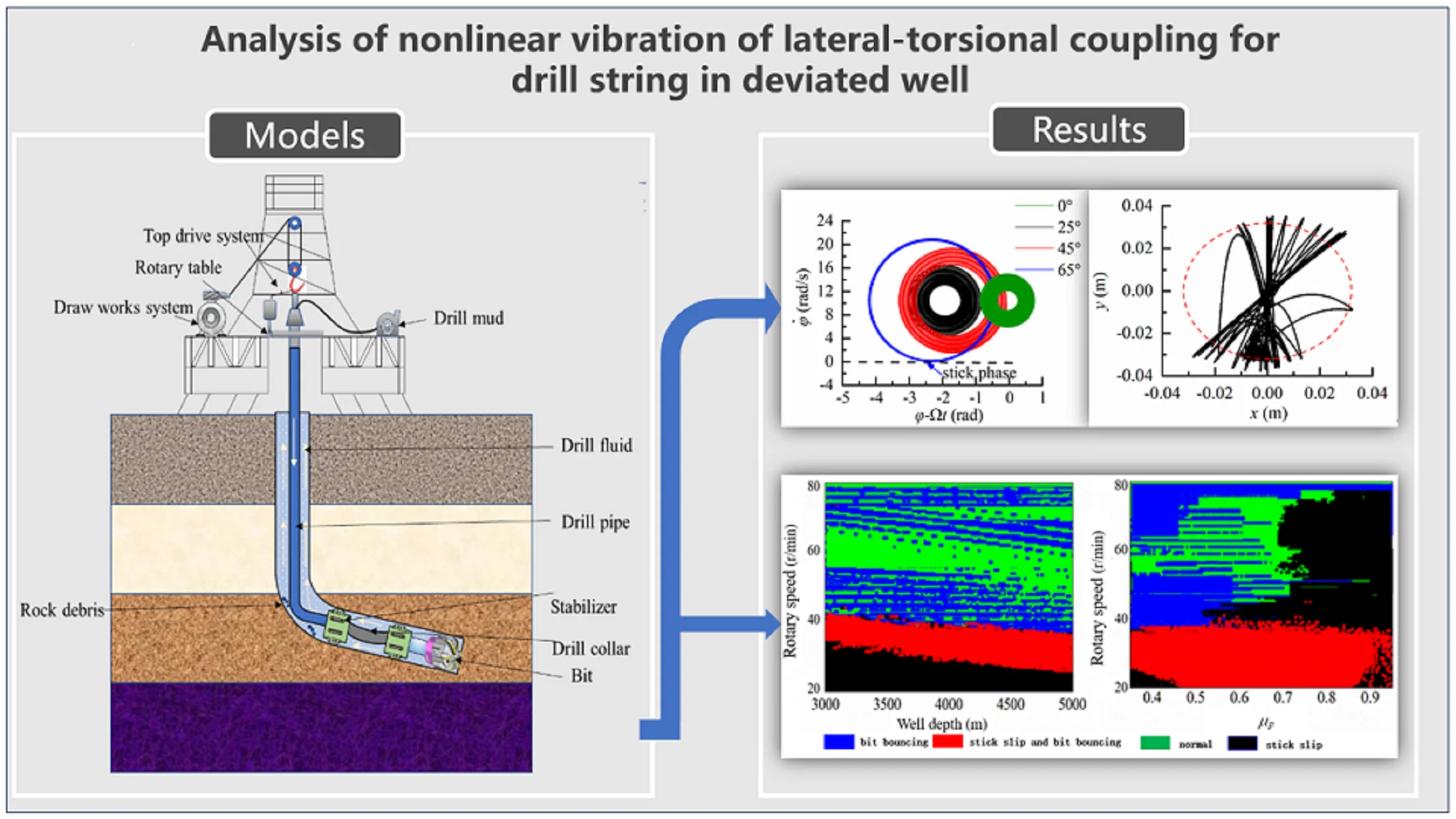
Highlights
- Nonlinear dynamic model of lateral-torsional coupling for drill string system is established.
- Friction losses in drill string systems is increased with higher well inclination angles.
- Torque transfer law is described by discrete torque-drag model.
1. Introduction
The drill string serves as vital equipment for oil or gas exploration and development, establishing a connection between the earth surface and the underground reservoir. The intricate dynamics of the drill string within the wellbore are influenced by weight on bit (WOB) and torque, resulting in a nonlinear movement characterized by multiple couplings [1-4]. This movement encompasses axial rotation, whirl motion around the wellbore center, and collision with the wellbore wall. Investigating the complex behavior of drill string systems in deviated wells represents an active area of research within drill string dynamics [5-6].
Numerous scholars have made significant strides in the field of drill string motion and vibration research. For instance, Jansen [7] investigated the existing conditions and stability of the bottom hole assembly (BHA) forward and backward whirling assuming it to be a Jeffcott rotor dynamic system. Melakhessou et al. [8] developed a four-degree-of-freedom model for drill string dynamics based on Jansen’s unbalanced mass model, focusing on local contact behavior between the drill string and borehole wall while disregarding the sliding effect. Liao et al. [9] extended the Melakhessou model into a five-degree-of-freedom drill string dynamics model by considering tilt effects between the rotor and stator, also proposing an integrated stick-slip, sliding, and rolling contact model to describe their contact behavior with the borehole wall. Kapitaniak et al. [10] constructed a predetermined set of parameters for a drill string dynamic system and elucidated how various rotational motions of the drill string are sensitive to initial conditions of the system. A year later, Kapitaniak et al. [11], through experimentation, validated their assumption regarding rotating motion in a two-degree-of-freedom dynamic model that characterizes nonlinear vibration properties of the drill string system. To investigate the stick-slip vibration of the drill string system, numerous scholars have also developed a model to describe the interaction between the drill tool and the rock. Jansen et al. [12] introduced a novel nonlinear function to depict the torque-on-bit interaction and dry friction along the drill collar. By combining the dry friction model with an exponential decay law, Navarro-López et al. [13] constructed an interaction model between the drill string and rock. Nogueira et al. [14] refined this interaction model by replacing it with a smooth model that offers improved computational efficiency compared to the dry friction model [15-16]. Regarding lateral vibrations, contact models primarily fall into two categories: linear elastic models [1, 17] and Hertzian contact laws [18-19].
However, the modeling studies primarily focus on drill string dynamics in vertical wells. To qualitatively investigate the impact of different inclination angles on the nonlinear motion of the drill string system, Liu et al. [20] simplified the BHA and drill pipe as a concentrated mass rotor and established a four-degree-of-freedom nonlinear dynamics model for the drill string system. Nevertheless, this model neglected the contact between the drill pipe and borehole wall. To describe lateral motion of BHA in highly deviated wells, Wang et al. [21] developed a finite element model that considers discontinuous interaction between drill strings and wellbore. In conclusion, significant progress has been made in researching dynamic properties of drill string systems in vertical wells. However, due to widespread application of directional and horizontal wells, most existing models for drill string dynamics less comprehensively consider frictional torque losses throughout the entire well section, interactions between drill strings and borehole walls or effects of drilling mechanical parameters on drill string dynamics [22]. Therefore, we have developed a nonlinear dynamics model to capture the lateral-torsional coupling of the drill string system in deviated wells. This model not only provides a robust framework for optimizing boreholes but also serves as a valuable reference for selecting drilling machinery parameters. At present, the dynamic model of drill string system in this paper is based on rotor dynamics, which cannot accurately predict the dynamic characteristics of drill pipe during drilling; based on Parida and Bal’s work [23-24], we will carry out the research on the dynamic characteristics of drill pipe in drill string system.
2. Dynamic model of drill string system
2.1. Dynamic model of BHA
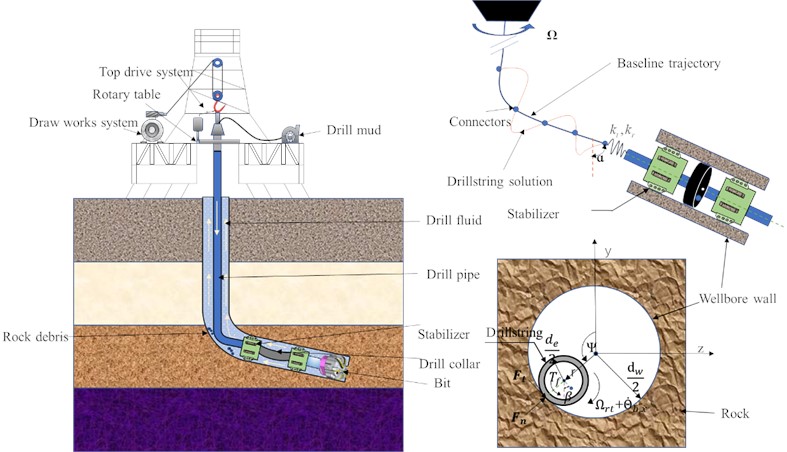
To investigate the dynamic characteristics of the drill string system in the deviated section, we establish a dynamic model using the Lagrange equation. The drill string system primarily consists of a drill pipe and BHA. During drilling, friction between the drill pipe and borehole wall occurs due to top drive action, which is analyzed using a discrete torque-drag model. To reduce lateral vibration and maintain stability, a stabilizer is incorporated into the BHA. Consequently, when studying lateral vibration in the BHA dynamics model, our focus is often limited to a specific region between the stabilizers. As depicted in Fig. 1, stabilizers within the BHA can be simplified as a rotor model with rigid support. The following assumptions are made simultaneously to streamline the computation process and ensure its accuracy:
1) The contact between the BHA and the borehole wall exhibits elastic behavior. 2) The contact between the drill pipe and the borehole wall remains continuous throughout. 3) The velocity of the BHA matches that of the drilling speed of the bit. 4) Neglecting any impact from axial vibration on drill string dynamics. 5) The drill pipe in the vertical well section is simplified as a linear torsion spring in the torsion direction, with its stiffness coefficient denoted as .
Taking centerof the borehole as the origin of the coordinate system for lateral vibration analysis of BHA, in the drilling process, there exists an eccentric distance between the mass center and geometric center of the BHA. Therefore, based on their geometric positional relationship, we can describe the position in coordinate frame as follows:
where, refers to the rotation angle of the rotor; and are geometric center displacement of the drill collar. The constraint condition, denoted by , signifies that the drill string is confined within the borehole.
Fig. 1Mechanical model of drill string system
The dynamic equation of the drill string system can be established by the Lagrange equation:
where, represents the generalized coordinate matrix, i.e., ; represents the generalized force matrix of the dynamic model, i.e., . , , and are the generalized force in the , and directions, respectively; , and are the kinetic energy, potential energy and energy dissipation functions of the drill string system, respectively:
where, represents the equivalent torsional stiffness of drill pipes; represents the equivalent transverse stiffness of BHA; is the equivalent rotational inertia of the drill string; and denote the lateral damping and torsional damping due to fluid interaction, respectively; is well deviation angle; is the equivalent mass of BHA; is the acceleration of gravity.
Substituting Eq. (3) into Eq. (2), the dynamic equations of drill string system can be obtained as:
Considering fluid resistance [7], the relative mass of BHA among stabilizers is expressed as follows:
where, and are the material density of BHA and drilling fluid, respectively; the outer and inner diameters of drill collar are represented by and , respectively; is the additional mass coefficient, and is BHA length between two stabilizers.
If a simple sine shape is assumed for the displacement field of a stabilized drill collar section (i.e., the first bending mode of a vibrating simply supported beam), the expressions for the equivalent lateral stiffness of the BHA can be considered, as shown Ref. [7]. The lateral stiffness of the drill string system can be determined as follows:
where, and are torque and weight on bit.
The torsional stiffness of the drill string system is denoted as follows:
where, is shearing elastic modulus of drill pipe.
The equivalent lateral and torsional dissipation coefficients, and , are influenced by the coupling effect between the drilling fluid and drill string:
where, is the drag coefficient, and is the friction coefficient of drilling fluid.
2.2. Model of drill string-borehole wall contact
When the radial displacement of the drill string exceeds the clearance between the drill pipe and the borehole wall, the movement of the drill string is constrained by the borehole wall. The interaction is accurately represented by employing a linear elastic contact function [17]. As depicted in Fig. 2(a), friction between the drill pipe and borehole wall generates two-component forces: normal force () and tangential force (), which can be described as follows:
where, and represent the equivalent stiffness and damping when the drill string contacting with the borehole wall, respectively.
The variablerepresents the drill string distortion caused by its contact with the borehole wall, , where, is the gap between the drill string and hole wall, ; is the bit diameter.
The friction coefficient, denoted as in Fig. 2(b), is contingent upon the relative velocity at the contact point between the drill string and borehole wall.
Fig. 2Model for drill string-borehole wall contact
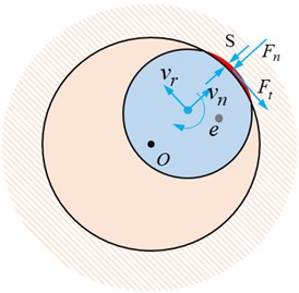
a) Contact between drill string and borehole wall
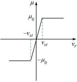
b) The friction mathematical model
In Fig. 2(b), critical velocity is a constant, as shown in Table 1. When relative velocity is less than critical velocity , the rotor is operated in the sticking state. The relative speed of drill string is expressed as:
The normal and tangential forces acting on the drill string in the coordinate system are decomposed into components along the and axes as follows:
The generalized force exerted on the drill string in the direction can be expressed as follows:
where, represents the top drive input torque; represents loss torque of the drill pipe; represents the friction torque generated by the interaction between BHA and borehole wall; represents the torque for bit cutting rock, i.e.:
where, coefficients , , , and represent the influential factors governing the interaction between the drill bit and the rock in this study. is the whirling angle of BHA, which can be determined by parameter based on geometrical relationship in Fig. 1.
2.3. Mathematical model of torque transfer in drill string
When investigating the dynamics of BHA in the drill string system, it is crucial to consider the friction losses of torque due to significant contact friction between the drill string and wellbore, particularly in curved sections. The torque transfer law of the drill string system is determined by employing a discrete torque-drag model [22]. It is assumed that the trajectory of the drill string aligns with that of the borehole, and the minimum curvature method is utilized to represent this trajectory accurately. The frictional losses caused by contact between the drill string and borehole wall are concentrated at specific discrete locations. As the diameter of the drill pipe sub exceeds that of regular pipes, these discrete points are selected at those subs, where a local Cartesian coordinate system is established for each point. The displacement along joint within this pipeline can be defined as:
where, represents the movement of drill string in direction, and represents the movement of drill string in direction.
The boundary conditions at the tool joint are given as:
Considering the joint effect of the drill string, the torque balance equations are written as:
where is Young’s modulus; is the moment of inertia of element; is the axial force in element at node ; is the shear force in element in the normal direction at node ; is the shear force in element in the binormal direction of node ; is the moment of rotation; is the wellbore curvature.
The aforementioned is resolved by incorporating the conditions of position continuity, slope continuity, and bending moment continuity.
The normal force () and the friction force () together constitute the contact force (). Thus, the magnitude of the contact force () is:
where denotes the contact force at node in the direction of the coordinate, and ; denotes the contact force at node in the direction of the coordinate, and ; denotes the friction coefficient of drill pipe.
The torque at the drill string joint exhibits discontinuity during rotation, which can be mathematically expressed as:
where, and represent the axial torque of element at node and element at node , respectively; is the radius of the tool joint at node . The torque losses caused by the friction contact between the drill pipe and the borehole wall can be calculated and used as the external torque of the drill string system in the equation of motion, which is expressed as:
where, is the torque losses caused by the friction contact.
3. Numerical simulation and results
To investigate the nonlinear vibration characteristics of lateral and torsional coupling in the drill string system within deviated sections, we established a dynamic model using the Lagrange equation. Subsequently, we numerically solve the dynamic equations employing the fourth-order Runge-Kutta method. The essential parameters utilized in this model are presented in Table 1.
Table 1Basic parameters of the model
Basic parameters | Values | Basic parameters | Values |
(Kg/m3) | 1296 | (m) | 0.1778 |
(Kg/m3) | 7860 | (m) | 0.085 |
1.7 | (m) | 0.2413 | |
0.35 | (m) | 0.00127 | |
0.2 | 1.0 | ||
0.014 | 8.5 | ||
1.51 | 5.47 | ||
(m) | 0.127 | 0.085 | |
WOB (kN) | 20 | (r/min) | 150 |
(m/s) | 0.02 | (m) | 20 |
0.3 | 0.3 |
3.1. Modeling verification of the drilling string system
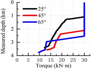
To verify the impact of borehole trajectory on torque transfer of the drill string system, numerical simulations are conducted to analyze the torque distribution under the borehole trajectory shown in Fig. 3. The torque distribution characteristics are examined for well inclination angles of 25°, 45°, and 65° in an inclined wellhole when WOB of 20 kN is applied, with the top drive output torque being 30 kN·m. The data presented here corresponds to the same dataset as Ref. [12]. Fig. 4 illustrates the torque transfer behavior of the drill string for different well trajectories. It is evident that most of the driving torque from the top drive is consumed during inclination building points and drilling deviated sections. When considering a deviation angle of 25° in the deviated section, it can be observed that cutting rock torque at the bit exceeds that at an inclination angle of 65°, which aligns well with findings reported in Ref. [12].
Fig. 3Well trajectory
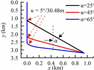
Fig. 4Torque transfer
3.2. Dynamic characteristics research of drill string system
3.2.1. Motion characteristics analysis of the BHA
To investigate the lateral vibration characteristics of the drill string, we present phase trajectories in theanddirections with different inclination angles, as depicted in Fig 5. Based on Fig. 5(a), it can be observed that the lateral displacement of the drill string remains within the gap between the drill string and borehole wall, indicating that in a vertical well, the drill string moves close to the center of the borehole without colliding with its walls. In Fig. 5(b), a significant change is evident in lateral velocity when exceeding this clearance, implying an occurrence of elastic collision between the drill string and borehole wall. Fig. 5(c) and 5(d) demonstrate that as inclination angle increases, displacement indirection becomes closer to the low side of borehole. The motion of BHA along thedirection is predominantly concentrated near the center at an inclination angle of 65°, while in thedirection it primarily focuses on lower region of borehole. Consequently, as inclination angle rises, lateral displacement amplitude of BHA is decreased while motion trajectory gradually concentrates on one side.
Fig. 5The motion characteristics of BHA in different well deviation angles
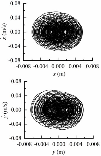
a) Phase trajectory of BHA in and directions as 0°
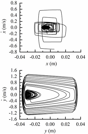
b) Phase trajectory of BHA in and directions as 25°
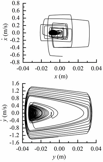
c) Phase trajectory of BHA in and directions as 45°
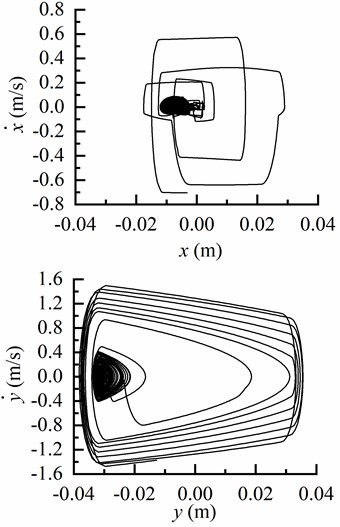
d) Phase trajectory of BHA in and directions as 65°
3.2.2. Drill string torsion analysis
The torsional vibration characteristics of the drill string at different inclination angles are illustrated in Fig. 6. It is evident that stick-slip motion does not occur when the inclination angle is 0° and 25°. However, at an inclination angle of 45°, stick-slip motion becomes apparent. Furthermore, as the inclination angle reaches 65°, the stick-slip motion of the drill string becomes more pronounced. In Fig. 6(a), the abscissa - represents the torsional angular displacement of the drill string relative to the bit; a negative value indicates that the bit rotates slower than the turntable. Additionally, it can be observed that there is less torsional angular displacement between the drill string and bit in vertical sections compared to deviated sections. To summarize, an increase in inclination angle within stable inclinations leads to a more prominent occurrence of stick-slip motion in the drill string.
Fig. 6Torsional vibration characteristics of BHA
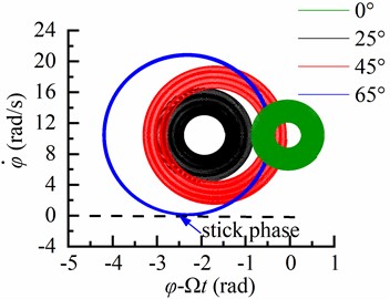
a) Phase trajectory of torsional vibration of BHA
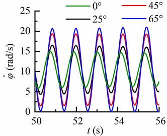
b) Torsional time domain of BHA
3.2.3. Motion trajectory of the BHA
The motion trajectories of the BHA with different inclination angles are depicted in Fig. 7, revealing a correlation between the motion trajectory of BHA and the inclination angle of well.
Fig. 7Lateral displacement and motion trajectory of the BHA
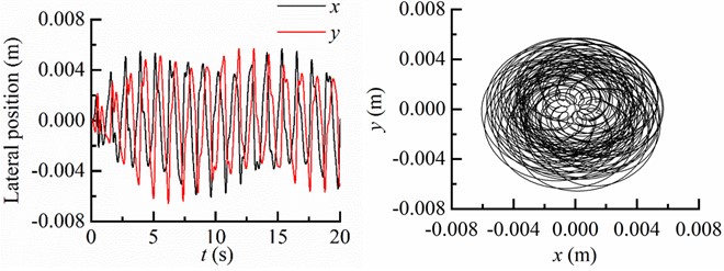
a) Lateral displacement and motion trajectory of BHA as 0°
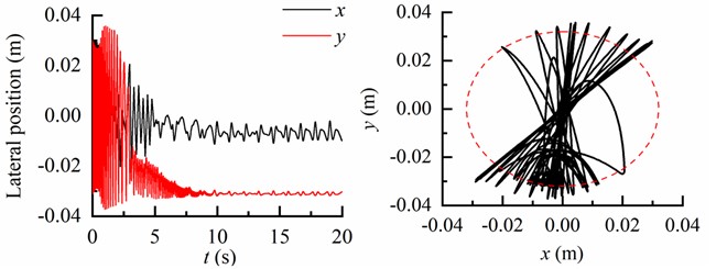
b) Lateral displacement and motion trajectory of BHA as 25°
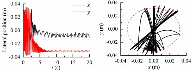
c) Lateral displacement and motion trajectory of BHA as 45°
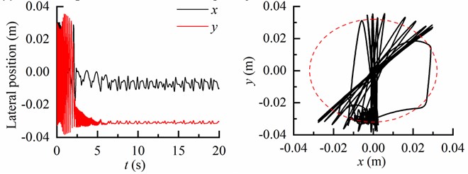
d) Lateral displacement and motion trajectory of BHA as 65°
In Fig. 7(a), both displacements in the and directions are significantly smaller than the clearance between the drill string and borehole wall, indicating an absence of contact between the BHA and borehole wall during drilling process of vertical well. At an inclination angle of 25°, there is a slightly higher collision frequency observed between the BHA and the low side of the borehole wall compared to that with the upper side (Fig. 7(b)). As shown in Fig. 7(c), there is a noticeable increase in collision frequency between the BHA and low side of borehole wall relative to that with upper side when inclined at 65°. Consequently, due to gravity influence, as inclination angle increases along borehole trajectory, drill string motion becomes more significantly affected.
3.2.4. Parameter analysis
The angular speed of the BHA affected by the rotary table speed was investigated at three different values: 5.23, 10.47, and 15.7 rad/s, respectively. As shown in Fig. 8, it is evident that the rotary table speed has a significant impact on the angular velocity of the BHA at various inclination angles. Notably, when the rotary table speed is set to 5.23 rad/s, the BHA experiences zero angular velocity and adheres to the borehole wall due to insufficient driving torque from the input torque of top drive for inducing elastic deformation in the drill string. However, as soon as the elastic strain energy surpasses frictional dissipation energy between the drill string and borehole wall, a transition occurs from a stick state to slip state within BHA rotation. Conversely, when the rotary table speed is increased to 15.7 rad/s, an excess driving torque is transmitted from rotary table to the BHA. As a result, this leads to a non-zero angular velocity without any occurrence of stick-slip phenomena.
Fig. 8Torsional response in the different rotary speed
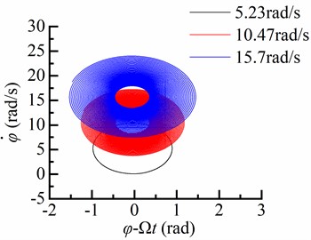
a) Well deviation angle 0°
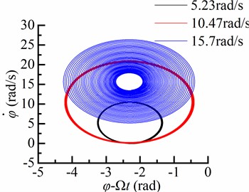
b) Well deviation angle 65°
Fig. 9Torsional response in the different WOB
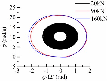
a) Well deviation angle 0°
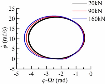
b) Well deviation angle 65°
The rotary table speed is given as 10.47 rad/s, and the variation law of the angular speed of BHA with differentWOB is illustrated in Fig. 9. As depicted in Fig. 9, the influence ofWOB on the angular speed of BHA is significant at various inclination angles. At aWOB of 20 kN, the angular speed of BHA remains positive in vertical wells without experiencing stick-slip phenomena within the drill string. However, stick-slip occurs when drilling in deviated wells using BHA. With aWOB of 90 kN, the BHA adheres to the borehole wall while exhibiting an amplitude for bit angular velocity approximately twice that of rotary table speed. When increasing the WOB to 160 kN, stick-slip motion becomes more pronounced within the drill string. Consequently, it can be concluded thatWOB significantly affects bit angular speed.
4. Drilling machinery parameter selection
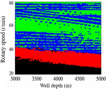
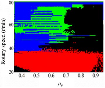
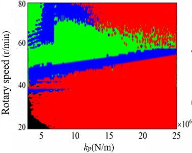
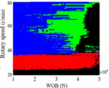
According to the theoretical computation model of drilling string system, the bit operation in different drilling machinery parameters can be determined by numerical computation. It can be seen from Fig. 10 that the bit in drilling process is emerged four states, i.e., bit bouncing, stick slip and bouncing, normal, stick slip. In drilling engineering, bit bouncing, stick slip and bouncing, stick slip of bit are appeared as the vibrations of drilling strings and borehole instability, therefore, normal operation of bit is a goal the drilling engineer pursued. As a result, the color in Fig. 10 representing idea drilling machinery parameter can be chosen.
Fig. 10Bit operation in different drilling parameters in α= 65°
a) = 0.35, = 4×10⁶, WOB = 3.5×10⁴
b) = 4×10⁶, = 3.5×10⁴ well depth 5000 m
c)= 0.35, = 3.5×10⁴ well depth 5000 m
d)= 0.35, = 4×10⁶ well depth 5000 m
In Fig. 10(a), when parameters = 0.35, = 4×10⁶, WOB = 3.5×10⁴, the idea range of rotary speed is decreased with improving the well depth, and idea rotary speed is ranged form 50-70 r/min. In Fig. 10(b), when = 4×10⁶, = 3.5×10⁴ in well depth 5000 m, the stick slip of bit is appeared with the increase of friction coefficient between drilling string and borehole wall; in normal drilling process friction coefficient is smaller than0.35, but borehole instability leads to the increase of friction coefficient easily. In Fig. 10(c), when = 0.35, = 3.5×10⁴ in well depth 5000 m, the bit bouncing is presented with the risen of strength of rock, and the idea range of rotary speed is decreased with improving strength of rock. In Fig. 10(d), when = 0.35, = 4×10⁶ in well depth 5000 m, the rotary speed can be controlled in range from 40 to 70 r/min, and the WOB should be restricted in range from 20 to 40 kN.
5. Conclusions
The dynamic behavior of the drill string in the deviated well is comprehensively analyzed by considering torsional and lateral vibrations. Numerical simulation is employed to discuss the vibration characteristics of the drill string, considering factors such as collision between the BHA and borehole wall, torque loss of drill string, and borehole structure. Several significant conclusions are summarized as follows:
1) In the vertical section, the torsional angular displacement of the drill string with respect to the bit is relatively small. However, in the deviated section, this displacement becomes greater and there is a noticeable phase lag between bit motion and rotary table rotation. When considering a deviation angle of 25° in the deviated section, it can be observed that cutting rock torque at the bit exceeds that at an inclination angle of 65°.
2) The influence of gravity on drill string motion becomes more pronounced as inclination angle increases. In vertical boreholes, collisions between BHA and borehole wall occur less frequently compared to deviated boreholes where collisions with low side of borehole wall are more frequent. When inclination angle more than 25°, there is a slightly higher collision frequency observed between the BHA and the low side of the borehole wall compared to that with the upper side.
3) Torsional vibration of the drill string is significantly affected by rotary speed andWOB. By selecting appropriateWOB and rotary table speed, it is possible to control bit motion for achieving normal operation. When increasing theWOB (weight on bit) to 160 kN, stick-slip motion becomes more pronounced within the drill string.
4) Through parametric dynamics analysis of the drill string system, the rotary speed can be controlled in range from 40 to 70 r/min, and theWOB should be restricted in range from 20 to 40 kN in well depth 5000 m.
References
-
X. Liu, N. Vlajic, X. Long, G. Meng, and B. Balachandran, “Nonlinear motions of a flexible rotor with a drill bit: stick-slip and delay effects,” Nonlinear Dynamics, Vol. 72, No. 1-2, pp. 61–77, Dec. 2012, https://doi.org/10.1007/s11071-012-0690-x
-
C. Germay, N. van de Wouw, H. Nijmeijer, and R. Sepulchre, “Nonlinear drillstring dynamics analysis,” SIAM Journal on Applied Dynamical Systems, Vol. 8, No. 2, pp. 527–553, Jan. 2009, https://doi.org/10.1137/060675848
-
Z. Huang, D. Xie, B. Xie, W. Zhang, F. Zhang, and L. He, “Investigation of PDC bit failure base on stick-slip vibration analysis of drilling string system plus drill bit,” Journal of Sound and Vibration, Vol. 417, No. 17, pp. 97–109, Mar. 2018, https://doi.org/10.1016/j.jsv.2017.11.053
-
P. Fang, K. Yang, G. Li, Q. Feng, and S. Ding, “Vibration-collision mechanism of dual-stabilizer bottom hole assembly system in vertical wellbore trajectory,” Journal of Vibroengineering, Vol. 25, No. 2, pp. 226–246, Mar. 2023, https://doi.org/10.21595/jve.2022.22813
-
A. Ghasemloonia, D. Geoff Rideout, and S. D. Butt, “A review of drillstring vibration modeling and suppression methods,” Journal of Petroleum Science and Engineering, Vol. 131, No. 17, pp. 150–164, Jul. 2015, https://doi.org/10.1016/j.petrol.2015.04.030
-
Y. A. Khulief and H. Al-Naser, “Finite element dynamic analysis of drillstrings,” Finite Elements in Analysis and Design, Vol. 41, No. 13, pp. 1270–1288, Jul. 2005, https://doi.org/10.1016/j.finel.2005.02.003
-
J. D. Jansen, “Non-linear rotor dynamics as applied to oilwell drillstring vibrations,” Journal of Sound and Vibration, Vol. 147, No. 1, pp. 115–135, May 1991, https://doi.org/10.1016/0022-460x(91)90687-f
-
H. Melakhessou, A. Berlioz, and G. Ferraris, “A nonlinear well-drillstring interaction model,” Journal of Vibration and Acoustics, Vol. 125, No. 1, pp. 46–52, Jan. 2003, https://doi.org/10.1115/1.1523071
-
C.-M. Liao, B. Balachandran, M. Karkoub, and Y. L. Abdel-Magid, “Drill-string dynamics: reduced-order models and experimental studies,” Journal of Vibration and Acoustics, Vol. 133, No. 4, pp. 3443–3445, Aug. 2011, https://doi.org/10.1115/1.4003406
-
M. Kapitaniak, V. Vaziri, J. Páez Chávez, and M. Wiercigroch, “Numerical study of forward and backward whirling of drill-string,” Journal of Computational and Nonlinear Dynamics, Vol. 12, No. 6, pp. 1–7, Nov. 2017, https://doi.org/10.1115/1.4037318
-
M. Kapitaniak, V. Vaziri, J. Páez Chávez, and M. Wiercigroch, “Experimental studies of forward and backward whirls of drill-string,” Mechanical Systems and Signal Processing, Vol. 100, pp. 454–465, Feb. 2018, https://doi.org/10.1016/j.ymssp.2017.07.014
-
J. D. Jansen and L. van den Steen, “Active damping of self-excited torsional vibrations in oil well drillstrings,” Journal of Sound and Vibration, Vol. 179, No. 4, pp. 647–668, Jan. 1995, https://doi.org/10.1006/jsvi.1995.0042
-
E. M. Navarro-López and D. Cortés, “Avoiding harmful oscillations in a drillstring through dynamical analysis,” Journal of Sound and Vibration, Vol. 307, No. 1-2, pp. 152–171, Oct. 2007, https://doi.org/10.1016/j.jsv.2007.06.037
-
B. F. Nogueira and T. G. Ritto, “Stochastic torsional stability of an oil drill-string,” Meccanica, Vol. 53, No. 11-12, pp. 3047–3060, May 2018, https://doi.org/10.1007/s11012-018-0859-6
-
L. P. P. de Moraes and M. A. Savi, “Drill-string vibration analysis considering an axial-torsional-lateral nonsmooth model,” Journal of Sound and Vibration, Vol. 438, pp. 220–237, Jan. 2019, https://doi.org/10.1016/j.jsv.2018.08.054
-
I. Gorelik, M. Neubauer, J. Wallaschek, and O. Höhn, “Model and method for a time-efficient analysis of lateral drillstring dynamics,” ASME Turbo Expo 2015: Turbine Technical Conference and Exposition, Vol. 56802, Jun. 2015, https://doi.org/10.1115/gt2015-42317
-
S. A. Al-Hiddabi, B. Samanta, and A. Seibi, “Non-linear control of torsional and bending vibrations of oilwell drillstrings,” Journal of Sound and Vibration, Vol. 265, No. 2, pp. 401–415, Aug. 2003, https://doi.org/10.1016/s0022-460x(02)01456-6
-
A. Ghasemloonia, D. Geoff Rideout, and S. D. Butt, “Analysis of multi-mode nonlinear coupled axial-transverse drillstring vibration in vibration assisted rotary drilling,” Journal of Petroleum Science and Engineering, Vol. 116, pp. 36–49, Apr. 2014, https://doi.org/10.1016/j.petrol.2014.02.014
-
P. D. Spanos, A. M. Chevallier, and N. P. Politis, “Nonlinear stochastic drill-string vibrations,” Journal of Vibration and Acoustics, Vol. 124, No. 4, pp. 512–518, Oct. 2002, https://doi.org/10.1115/1.1502669
-
Y. Liu and D. Gao, “A nonlinear dynamic model for characterizing downhole motions of drill-string in a deviated well,” Journal of Natural Gas Science and Engineering, Vol. 38, pp. 466–474, Feb. 2017, https://doi.org/10.1016/j.jngse.2017.01.006
-
H. Wang et al., “Modeling and analyzing the motion state of bottom hole assembly in highly deviated wells,” Journal of Petroleum Science and Engineering, Vol. 170, pp. 763–771, Nov. 2018, https://doi.org/10.1016/j.petrol.2018.07.005
-
R. F. Mitchell, A. Bjørset, and G. Grindhaug, “Drillstring analysis with a discrete torque/drag model,” SPE Drilling and Completion, Vol. 30, No. 1, pp. 5–16, Mar. 2015, https://doi.org/10.2118/163477-pa
-
S. P. Parida, S. Sahoo, and P. C. Jena, “Prediction of multiple transverse cracks in a composite beam using hybrid RNN-mPSO technique,” Proceedings of the Institution of Mechanical Engineers, Part C: Journal of Mechanical Engineering Science, Mar. 2024, https://doi.org/10.1177/09544062241239415
-
B. B. Bal, S. P. Parida, and P. C. Jena, “Damage assessment of beam structure using dynamic parameters,” in Lecture Notes in Mechanical Engineering, Singapore: Springer Singapore, 2020, pp. 175–183, https://doi.org/10.1007/978-981-15-2696-1_17
About this article
The research leading to these results received funding from (the PetroChina Innovation Foundation, China [No. 2020D-5007-0312]) and (the PetroChina-Southwest Petroleum University Innovation Consortium Project, China [No. 2020CX040103]).
The datasets generated during and/or analyzed during the current study are available from the corresponding author on reasonable request.
Zuwen Tao: conceptualization, investigation, writing – original draft preparation. Yingfeng Meng: data curation, software. Qunfang Feng: formal analysis, validation, writing – review and editing. Kang Yang: funding acquisition, visualization. Weitang Kang: project administration. Xiao Huang: resources. Pan Fang: methodology, supervision.
The authors declare that they have no conflict of interest.
