Abstract
Slider-crank mechanisms are widely used in various industrial and technological machines. This paper considers a generalized diagram of a slider-crank mechanism, on the connecting rod of which an imbalanced mass can be fixed. In such a case, the slider-crank mechanism can be employed as an inertial vibration exciter. The aim of this research is to justify the geometric parameters of the mechanism to ensure a predetermined elliptical trajectory of the imbalanced mass motion. The research methodology involves the analytical derivation of the motion equations for a connecting rod point and solving the problem of synthesizing the geometric parameters of the mechanism based on the given trajectory of this point. The obtained results are presented in the form of displacements and trajectories for the connecting rod point of a specific slider-crank mechanism. The major novelty of this research lies in the further development of the theory of slider-crank mechanism synthesis for use in inertial vibration exciters. The derived analytical dependencies can be utilized by designers and engineers in the development of new types of vibration exciters for various industrial and technological vibratory equipment.
Highlights
- Analytical expressions were derived for the coordinates of a connecting rod point in a slider-crank mechanism, considering its potential use for vibration excitation.
- A synthesis technique was developed to determine the mechanism's required geometric parameters in order to produce a predetermined elliptical trajectory for the connecting rod point.
- The study provides equations that link the desired ellipse parameters, specifically the major and minor axes lengths and the inclination angle, to the necessary mechanism geometry.
- The proposed synthesis methodology was validated using mathematical modeling within the Mathematica software and through virtual simulations conducted in SolidWorks, confirming its accuracy.
- Results demonstrate that slider-crank mechanisms can be successfully synthesized to generate specific elliptical paths, making them suitable for application as inertial vibration exciters in various types of equipment.
1. Introduction
Slider-crank mechanisms are integral components in the design and operation of various industrial and technological equipment, in particular, vibratory machines that are widely employed across industries for material handling, conveying, screening, sieving, and compaction processes [1], [2]. These mechanisms are valued for their ability to convert rotational motion into precise reciprocating motion, making them ideal for generating controlled vibrations [3], [4].
The implementation of slider-crank mechanisms as part of inertial vibration exciters offers a robust solution for controlling the frequency, amplitude, and trajectory of vibrations of the corresponding working members (plates, trays, sieves, etc.) [5]-[7]. By attaching an unbalanced mass to the crank, slider, or connecting rod, the mechanism can induce periodic oscillations, which are transmitted to the equipment, enabling the desired vibratory motion [8], [9]. This method allows for the tuning of vibrations to match specific operational requirements, thus enhancing the efficiency and precision of vibratory processes [10], [11]. For example, the studies [12]-[14] focus on the development and analysis of mathematical models, motion dynamics, and the impact of design parameters on the locomotion performance of wheeled vibration-driven robots, with an emphasis on vibro-impact systems, impact gap effects, and pantograph-type suspensions.
The effectiveness of slider-crank mechanisms in vibration exciters is largely dependent on their geometric parameters, which dictate the resulting motion of the unbalanced mass and, consequently, the vibration characteristics [15], [16]. A key challenge in their design is ensuring that the mechanism produces a well-defined, stable trajectory, typically elliptical, that aligns with the operational needs of the equipment [17]. Understanding and optimizing the trajectory-based synthesis of slider-crank mechanisms is therefore critical to advancing the performance of vibratory equipment across a range of industrial applications [18], [19].
In this context, the study of slider-crank mechanism implementation in vibration exciters focuses on the analytical and practical aspects of design optimization, with the aim of achieving reliable, high-performance vibratory systems [20], [21]. Following the authors’ previous research [22]-[24] on the potential use of slider-crank mechanisms in drives of vibratory machines, this article explores the synthesis of these mechanisms for generating controlled vibrations, contributing to the development of more efficient and versatile vibratory equipment. The major scientific novelty of this research lies in the further development of the theory of slider-crank mechanism synthesis for use in inertial vibration exciters. Herewith, the main aim of the paper is to justify the geometric parameters of the mechanism to ensure a predetermined elliptical trajectory of the connecting rod point at which the imbalanced mass can be fixed.
2. Research methodology
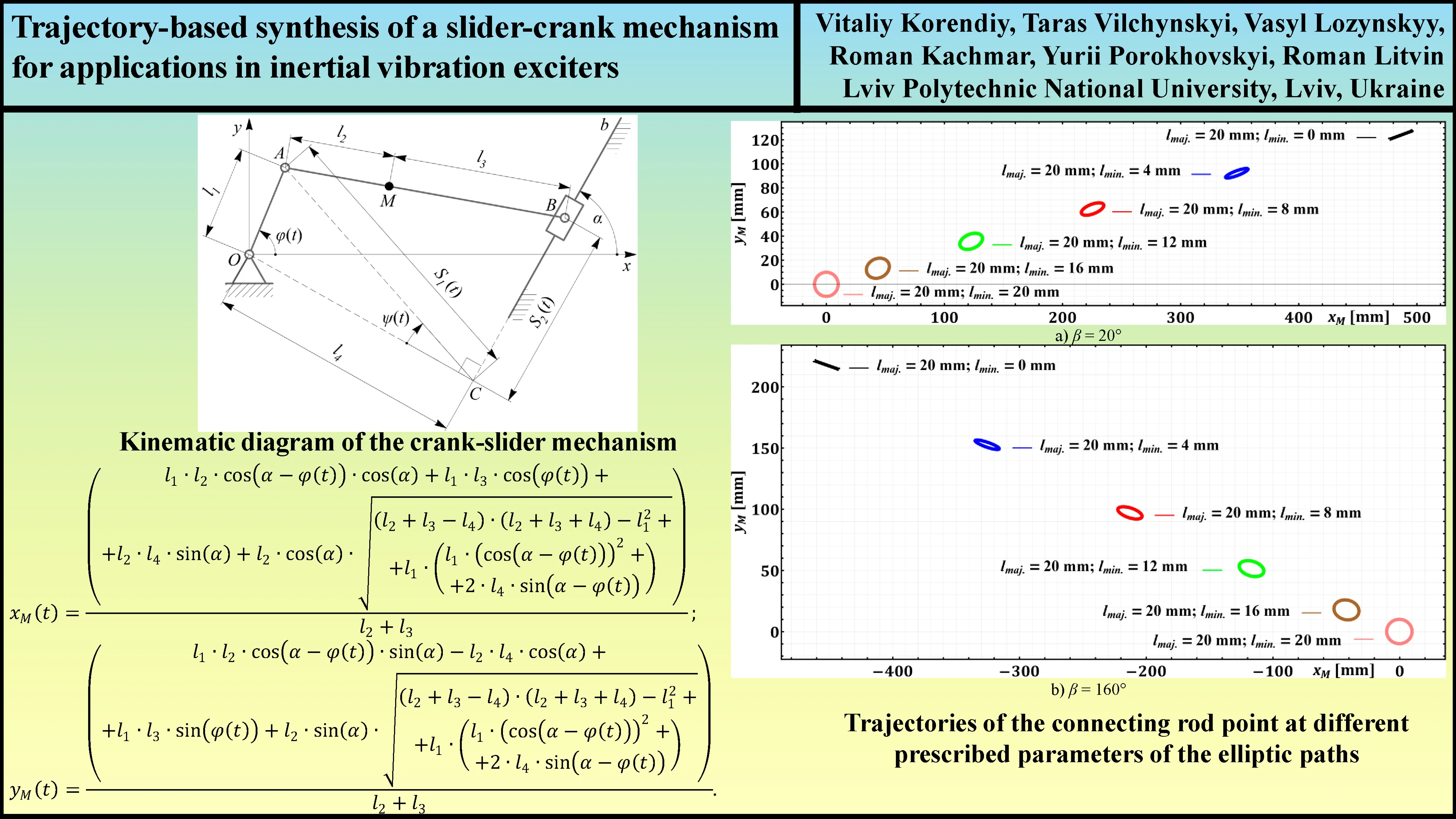
The generalized kinematic diagram of the crank-slider mechanism is presented in Fig. 1. It consists of the stationary base and three movable links: crank OA, connecting rod AB, and slider B. The links are connected by three revolute joints (hinges) located at points O, A, and B. The slider B translationally moves along the fixed guide . The angular position of the crank OA is described by the generalized coordinate . The positions of all the members of the mechanism depend on the coordinate and geometrical parameters defined in Fig. 1. Adopting the Cartesian coordinate system , let us deduce the analytical expressions for determining the corresponding coordinates of the points A, B, C, and M:
Fig. 1Generalized kinematic diagram of the crank-slider mechanism
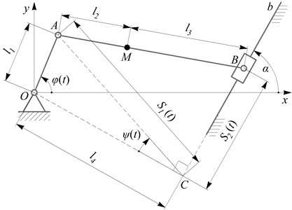
In order to determine the coordinates of the point B, let us first determine the following changeable geometrical parameters: distance between the points C and A; distance between the points C and A; angle between the lines CO and CA:
Therefore, the coordinates of the slider B can be calculated as follows:
Considering the point M, at which the imbalanced mass can be attached, its coordinates can be presented as follows:
Substantiating Eqs. (1-6) into Eq. (7), the final analytical expressions for defining the coordinates of the point M can be derived in the following form:
By finding the derivatives of the coordinates and with respect to time, it is possible to determine the corresponding velocities and accelerations of the point M. Due to the large analytical expressions, let us omit their presentation here.
In general, the studied slider-crank mechanism with an imbalanced mass placed on the connecting rod is characterized by five unknown geometric parameters (, , , , ) that determine the trajectory of the point M on the connecting rod. Therefore, the primary task of synthesizing the mechanism for its use as a vibration exciter is to establish analytical dependencies for calculating these geometric parameters to ensure a predetermined trajectory of the point M.
First, let us impose the constraints on the geometric parameters that define the feasibility of the considered slider-crank mechanism:
The angle between the major axis of the elliptic path of the point M on the connecting rod and the horizontal -axis depends on the lengths of the links (, , , ) and angle as follows:
The lengths of the major and minor axes of the elliptic path of the point M on the connecting rod can be approximately determined as follows:
3. Results and discussion
Let us consider an example of synthesizing the geometric parameters of a slider-crank mechanism, where the connecting rod point is required to move along an elliptical trajectory with the following ellipse parameters: 20°, 160°, 20 mm, 0, 4, 8, 12, 16, 20 mm. By adopting the crank length and the distance 50 mm based on the specific design of the vibration exciter [24], the remaining geometrical parameters (, , ) of the mechanism can be determined by solving the system of Eqs. (10-12), taking into account the constraints presented in Eqs. (9). Due to the large analytical expressions obtained for , , , let us omit their presentation in this paper and let us just give the final results of calculations conducted in the Mathematica software for different values of and :
– 20° and 0, 4, 8, 12, 16, 20 mm: 502, 360, 234, 128, 46, 0 mm, 0, 90, 156, 192, 182, 61 mm, 20°, 21.3°, 22.9°, 25.2°, 29.7°, 0…180°.
– 160° and 0, 4, 8, 12, 16, 20 mm: 502, 360, 234, 128, 46, 0 mm, 0, 90, 156, 192, 182, 61 mm, 160°, 161.3°, 162.9°, 165.2°, 169.7°, 0…180°.
Considering the obtained modeling results shown in Fig. 2, the simulated trajectories of the connecting rod point M fully satisfy the prescribed parameters of the elliptical paths for the mentioned sets of the synthesized geometrical dimensions of the links. Herewith, it is necessary to mention that circular trajectory of the connecting rod point can be described at any value of .
The next stage of verifying the correctness of the derived analytical expressions involves justifying the feasibility of altering the inclination angle of the major axis of the elliptical trajectory of the connecting rod point relative to the horizontal axis. By setting the angle equal to 0, 30°, 60°, 90°, 120°, 150°, 180° and adopting the following parameters for the elliptical trajectory: 22 mm, 4 mm, the corresponding geometric dimensions of the mechanism’s links were synthesized based on the system of equations (10-12): 88 mm, 22 mm, 5°, 35°, 65°, 95°, 125°, 155°, 185°, and the resulting paths of the connecting rod point are plotted in Fig. 3(a). The shape of the elliptical trajectory and the synthesized lengths of the links remain unchanged with variations in the angle . Therefore, to adjust the inclination angle of the elliptical path of the connecting rod point relative to the horizontal axis, it is sufficient to rotate the entire mechanism around the driving crank hinge. This conclusion will be applied in the further design of a controllable inertial vibration exciter based on the slider-crank mechanism.
The final stage of the research involves conducting virtual experiments to explore the capabilities of generating elliptical trajectories by the connecting rod point using the SolidWorks software. The following parameters of the mechanism are studied: 90°, 20 mm, 40 mm, 0, 10, 20, 30, 40, 50, 60, 70, 80 mm, 80, 70, 60, 50, 50, 30, 20, 10, 0 mm. The corresponding simulation results are presented in Fig. 3(b). As shown in the SolidWorks simulation window, the connecting rod point can perform a circular motion (when it is at the hinge joining the crank to the connecting rod) and can move along a linear trajectory (when it coincides with the hinge joining the connecting rod to the slider). All intermediate positions of the connecting rod point provide elliptical trajectories of motion.
Thus, by adjusting the parameters , , and , which define the position of the connecting rod point, it is possible to achieve the desired shape of the elliptical trajectory along which the imbalanced mass of the inertial vibration exciter can potentially move. This allows for controlling the trajectory of the working member of a vibratory machine (conveyor, sieve, screen, etc.).
Fig. 2Trajectories of the connecting rod point at different prescribed parameters of the elliptic paths
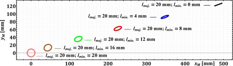
a) 20°
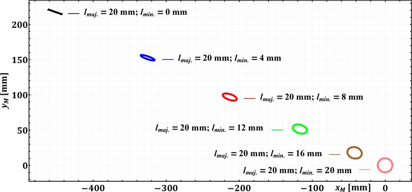
b) 160°
Fig. 3Trajectories of the connecting rod point at different angles β and lengths l2 and l3
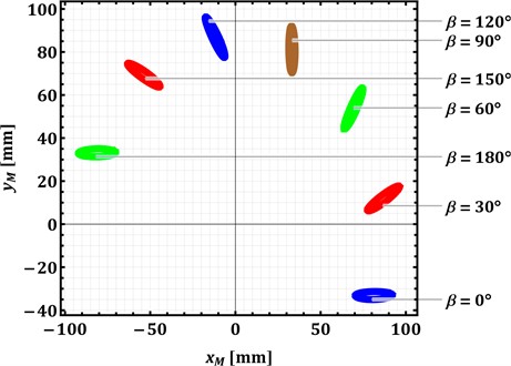
a) Modeling in Mathematica software
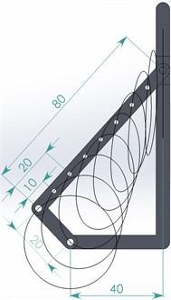
b) Simulation in SolidWorks
The proposed approach of equipping the inertial vibration exciter with the slider-crank mechanism allows for adjusting the motion parameters of an imbalanced mass, which is crucial for optimizing the performance of vibratory equipment. The parametric synthesis technique considered above enables achieving the desired shapes and amplitude range of vibrations, which, in turn, can affect the efficiency and productivity of the vibratory equipment.
4. Conclusions
The paper considers the generalized kinematic diagram of the slider-crank mechanism, on the connecting rod of which there can be fixed the imbalanced mass of the inertial vibration exciter. The kinematic analysis of the mechanism is performed and the analytical expressions for determining the coordinates of the connecting rod point are derived. Based on the performed analysis, the technique of synthesizing the geometrical dimensions of the mechanism is developed that allows the point to generate elliptical trajectories with the prescribed parameters: the lengths of the major and minor axes and the angle between the major axis and the horizontal plane. The proposed technique was tested during mathematical modeling of the connecting rod point motion in the Mathematica software. In addition, the virtual experiments of the slider-crank mechanism motion are carried out in the SolidWorks software. The obtained results substantiate the possibilities of utilizing the slider-crank mechanisms in inertial vibration exciters.
References
-
V. Korendiy, O. Lanets, O. Kachur, P. Dmyterko, and R. Kachmar, “Determination of inertia-stiffness parameters and motion modelling of three-mass vibratory system with crank excitation mechanism,” Vibroengineering Procedia, Vol. 36, pp. 7–12, Mar. 2021, https://doi.org/10.21595/vp.2021.21924
-
V. Korendiy, O. Kachur, and P. Dmyterko, “Kinematic analysis of an oscillatory system of a shaking conveyor-separator,” in Lecture Notes in Mechanical Engineering, Cham: Springer International Publishing, 2021, pp. 592–601, https://doi.org/10.1007/978-3-030-91327-4_57
-
O. Kachur and V. Korendiy, “Dynamic behavior of vibratory screening conveyor equipped with crank-type exciter,” in Lecture Notes in Mechanical Engineering, Cham: Springer Nature Switzerland, 2023, pp. 44–53, https://doi.org/10.1007/978-3-031-32774-2_5
-
S. Kilikevičius, K. Liutkauskienė, E. Uldinskas, R. El Banna, and A. Fedaravičius, “Omnidirectional manipulation of microparticles on a platform subjected to circular motion applying dynamic dry friction Control,” Micromachines, Vol. 13, No. 5, p. 711, Apr. 2022, https://doi.org/10.3390/mi13050711
-
D. Lin et al., “A rigid-flexible coupled dynamic model of a flip-flow vibrating screen considering the effects of processed materials,” Powder Technology, Vol. 427, p. 118753, Sep. 2023, https://doi.org/10.1016/j.powtec.2023.118753
-
J. Feliks, P. Tomach, D. Foszcz, T. Gawenda, and T. Olejnik, “Research on the new drive of a laboratory screen with rectilinear vibrations in transient states,” Energies, Vol. 14, No. 24, p. 8444, Dec. 2021, https://doi.org/10.3390/en14248444
-
A. Sinha, S. K. Bharti, A. K. Samantaray, G. Chakraborty, and R. Bhattacharyya, “Sommerfeld effect in an oscillator with a reciprocating mass,” Nonlinear Dynamics, Vol. 93, No. 3, pp. 1719–1739, Apr. 2018, https://doi.org/10.1007/s11071-018-4287-x
-
M. Buzzoni, M. Battarra, E. Mucchi, and G. Dalpiaz, “Motion analysis of a linear vibratory feeder: Dynamic modeling and experimental verification,” Mechanism and Machine Theory, Vol. 114, pp. 98–110, Aug. 2017, https://doi.org/10.1016/j.mechmachtheory.2017.04.006
-
V. V. Mikheyev, “New type of vibration generator with vibratory force oriented in preferred direction,” Journal of Vibration Engineering and Technologies, Vol. 6, No. 2, pp. 149–154, Jun. 2018, https://doi.org/10.1007/s42417-018-0025-4
-
G. F. Alışverişçi, “The nonlinear behavior of vibrational conveyers with single‐mass crank‐and‐rod exciters,” Mathematical Problems in Engineering, Vol. 2012, No. 1, p. 53418, Oct. 2012, https://doi.org/10.1155/2012/534189
-
H. Li, C. Liu, L. Shen, and L. Zhao, “Vibration characteristics of an industrial‐scale flip‐flow screen with crank‐link structure and parameters optimization,” Shock and Vibration, Vol. 2021, No. 1, p. 26126, Sep. 2021, https://doi.org/10.1155/2021/2612634
-
V. Korendiy, V. Gursky, O. Kachur, P. Dmyterko, O. Kotsiumbas, and O. Havrylchenko, “Mathematical model and motion analysis of a wheeled vibro-impact locomotion system,” Vibroengineering Procedia, Vol. 41, pp. 77–83, Apr. 2022, https://doi.org/10.21595/vp.2022.22422
-
V. Korendiy, O. Kachur, V. Gurskyi, and P. Krot, “Studying the influence of the impact gap value on the average translational speed of the wheeled vibration-driven robot,” Engineering Proceedings, Vol. 24, No. 1, p. 25, 2022, https://doi.org/10.3390/iecma2022-12897
-
V. Korendiy and O. Kachur, “Locomotion characteristics of a wheeled vibration-driven robot with an enhanced pantograph-type suspension,” Frontiers in Robotics and AI, Vol. 10, p. 12391, Aug. 2023, https://doi.org/10.3389/frobt.2023.1239137
-
W. Zhang, Z. Liu, W. Liu, J. Sun, and H. Lu, “Dimensional synthesis of a spherical linkage crank slider mechanism for motion generation using an optimization algorithm,” Mechanical Sciences, Vol. 14, No. 1, pp. 125–142, Mar. 2023, https://doi.org/10.5194/ms-14-125-2023
-
S. Ahamad, S. Khan, and A. Mohammad, “Structural synthesis of planar kinematic chains and their detection of isomorphism,” Journal of The Institution of Engineers (India): Series C, Vol. 105, No. 1, pp. 141–159, Jan. 2024, https://doi.org/10.1007/s40032-023-01012-0
-
J. Beckers, T. Verstraten, B. Verrelst, F. Contino, and J. van Mierlo, “Analysis of the dynamics of a slider-crank mechanism locally actuated with an act-and-wait controller,” Mechanism and Machine Theory, Vol. 159, p. 104253, May 2021, https://doi.org/10.1016/j.mechmachtheory.2021.104253
-
M. A. Ben Abdallah, I. Khemili, N. Aifaoui, and M. A. Laribi, “Computer-aided design tool for typical flexible mechanisms synthesis by means of evolutionary algorithms,” Robotica, Vol. 42, No. 4, pp. 1172–1211, Mar. 2024, https://doi.org/10.1017/s0263574724000171
-
O. Denizhan, “Comparison of different supervised learning algorithms for position analysis of the slider-crank mechanism,” Alexandria Engineering Journal, Vol. 92, pp. 39–49, Apr. 2024, https://doi.org/10.1016/j.aej.2024.02.055
-
C.-N. Wang, T. D.-M. Le, and N. T. Huynh, “Optimal rigid-flexible dynamic of space slider-crank mechanism with clearance joints,” Sādhanā, Vol. 48, No. 2, p. 44, Mar. 2023, https://doi.org/10.1007/s12046-023-02085-4
-
M. H. Ghazwani and V. Pham, “Investigating behavior of slider-crank mechanisms with bearing failures using vibration analysis techniques,” Mathematics, Vol. 12, No. 4, p. 544, Feb. 2024, https://doi.org/10.3390/math12040544
-
O. Lanets, O. Kachur, V. Korendiy, and V. Lozynskyy, “Controllable crank mechanism for exciting oscillations of vibratory equipment,” in Lecture Notes in Mechanical Engineering, Cham: Springer International Publishing, 2021, pp. 43–52, https://doi.org/10.1007/978-3-030-77823-1_5
-
V. Korendiy et al., “Kinematic and dynamic analysis of three-mass oscillatory system of vibro-impact plate compactor with crank excitation mechanism,” Vibroengineering Procedia, Vol. 40, pp. 14–19, Feb. 2022, https://doi.org/10.21595/vp.2022.22393
-
V. Korendiy, V. Gursky, P. Krot, and O. Kachur, “Dynamic analysis of three-mass vibratory system with twin crank-slider excitation mechanism,” Vibrations in Physical Systems, Vol. 34, No. 2, pp. 1–9, Jan. 2023, https://doi.org/10.21008/j.0860-6897.2023.2.26
About this article

The authors have not disclosed any funding.
The datasets generated during and/or analyzed during the current study are available from the corresponding author on reasonable request.
The authors declare that they have no conflict of interest.
