Abstract
In order to improve the stability and reliability of medicinal grinding machine, reduce vibration and noise, and enhance the strength of load-bearing, a scheme for optimizing dynamic response characteristics without increasing mass was proposed based on multi-objective optimization methods. Using the finite element method, the modal analysis was conducted on the entire model of the grinding machine to determine its natural frequencies and vibration modes. The structural optimization design was carried out with the optimization goal of having a sixth-order natural frequency below 30 Hz and a seventh-order natural frequency above 100 Hz. The stress distribution was obtained by conducting the strength analysis on the connecting rod structure. The optimization design of the structure was carried out with the minimum value of the stress peak and the maximum value of the fatigue safety factor as the optimization objectives. The results show that the multi-objective optimization method can make the equipment avoid the resonance zone and reduce the peak stress, which is of great significance for improving the performance of the medical grinding machine.
Highlights
- Using the finite element method, the modal analysis was conducted on the entire model of the grinding machine to determine its natural frequencies and vibration modes.
- The structural optimization design was carried out with the optimization goal of having a sixth-order natural frequency below 30Hz and a seventh-order natural frequency above 100Hz.
- The stress distribution was obtained by conducting the strength analysis on the connecting rod structure.
1. Introduction
Medical grinding machine is classified as basic and general instruments, and is also specific equipment in medical experiment management systems. It depends on the vibrational force generated by mechanical vibration, not only enhancing the grinding efficiency but also guaranteeing the grinding and crushing outcome. Two principal issues are present in the existing medical grinding machines, encompassing the problem of intense vibration throughout the entire machine and the issue of inadequate strength of key components [1]. Firstly, when the motor operates at a high speed during functioning, a vigorous vibration occurs in the grinding machine casing during startup and shutdown, accompanied by a certain degree of noise [2, 3]. Secondly, after several months of utilization, a batch of grinding machine products consistently encounter the problem of fracture and damage to the connecting rod and motor support, which results in the grinding machine being incapable of functioning normally due to the fracture and damage of these key components. Additionally, the contemporary design of grinding machine structures is primarily conducted through empirical formulas and product trials, lacking a theoretical calculation foundation for the design selection of specific structure plans. It proves challenging to put forward effective design proposals, ultimately resulting in an elongated R&D cycle and frequent structural failure issues. Within the management of medical equipment, boosting the reliability and service life of the equipment constitutes an essential requirement. Therefore, the dynamic characteristics analysis, especially the modal and strength responses, is crucial for evaluating the performance of critical components [4, 5]. Based on the dynamic response results, an effective optimization design scheme can be proposed to avoid blind design and improve product design efficiency, providing reference for the optimization design of similar instruments and equipment.
2. Modal and strength analysis of critical components
2.1. Structural composition and working principle
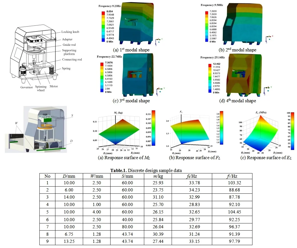
The core motion mechanism of the medical grinding machine is a vertically installed concentric crank-linkage mechanism, as shown in Fig. 1. During operation, the motor shaft of the driving motor is initially connected via a key, subsequently driving the rotating disc to rotate. Subsequently, the rotating disc actuates one end of the linkage, while the other end of the linkage prompts the movement of the linear bearing guide rod. Ultimately, the guide rod drives the sample tube adapter to perform vertical reciprocating motion. Among these, the speed and operating time of the motor are regulated by the speed governor, and the guide rod constitutes a sliding pair with the fixed sleeve on the support table.
Fig. 1Structural composition of medical grinding machine
The grinding instrument attains high-speed vertical reciprocating movement of the sample tube adapter via a crank-connecting rod mechanism. The adapter is capable of concurrently accommodating multiple 5 ml sample tubes, each containing solid samples and grinding balls that are in need of grinding. The adapter induces high-speed vibration of the sample tubes, and the grinding balls within the sample tubes exert a vigorous impact and collision on the samples, thereby fulfilling the objective of grinding and pulverizing the samples. The grinding apparatus employs vertical vibration for grinding and pulverizing samples. In practical applications, it was discovered that the motor operates at a high speed during operation, and the vibration system generates considerable vibrations. The vibrations are especially intense during the start-up and shut-down phases, and there is a certain amount of noise throughout the operation process. Hence, the dynamic characteristics of the transmission mechanism and the shell part were analyzed independently.
2.2. Modal analysis of transmission mechanism and shell part
The finite element model of the grinding machine assembly constitutes an assembly comprising 26 solid components, and the contact states among these components demand rational configuration. Within the ANSYS Workbench software, there exist two types of contact settings: linear contact and nonlinear contact. Nevertheless, given that ordinary modal analysis is of a linear nature, the software will transform nonlinear contact into linear contact. In the ordinary modal test, the contacting parts of the structure are firmly coupled, and the nonlinear contact state is arduous to attain in the modal test. Consequently, the contact conversion within the software is justifiable. In the modal analysis of the grinding machine assembly, it is postulated that the components are firmly joined, and the contact type between the components of the grinding machine is designated as bound contact, which prohibits any separation, sliding, or penetration among the contacting components. The contact algorithm for the components of the grinding machine is selected as the extended Lagrange algorithm, which is based on the detection of Gaussian integration points and is prone to convergence in the bound contact between the components of the grinding machine. Regarding the constraint boundary conditions, the contact surface between the four rubber pads at the bottom of the grinding machine and the ground is configured as a fixed constraint, restricting the 6 degrees of freedom of the bottom surface of the rubber pads.
When the shell is taken into account, the modal analysis results of the entire grinding machine are presented in Fig. 2. It can be observed that after considering the shell, the first four modal frequencies of the entire grinding machine fall within the range of 0-30 Hz. Among them, the corresponding mode parameters of the third mode are -axis vibration. Thus, the probability of resonance during the normal operation of the grinding machine is higher, which also implies that the third mode is the predominant mode in the -axis direction. After considering the shell, the mass of the finite element model of the entire grinding machine rises, and the modal natural frequency values decline. The modal shapes are analogous, and the trend of swinging and twisting vibrations in the horizontal direction reduces. In engineering practice, resonance phenomena do not merely occur at a single natural frequency value but within the resonance frequency band close to the natural frequency value. Based on the simulation results, the probability of the entire grinding machine resonating is extremely high when the working excitation frequency is within the range of 30-35 Hz.
Fig. 2Results of the first four modal shapes of shell part
a) 1st modal shape
b) 2nd modal shape
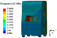
c) 3rd modal shape
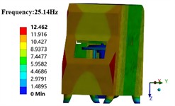
d) 4th modal shape
2.3. Analysis of connecting rod strength
Based on the working principle and parameter analysis of the crank connecting rod mechanism, the grinder undergoes alternating tensile and compressive loads within one motion cycle, with a maximum tensile load of 733.7 N. Supposing that the direction of the tensile and compressive loads exerted on the connecting rod of the grinder aligns with the axis of the rod, that is, the direction of the load is coincident with the line connecting the two ends of the connecting rod.
The maximum values of the tensile and compressive loads are utilized as the load boundary conditions for the static strength analysis of the grinder connecting rod. Regarding the contact settings, the circular holes at both ends of the bearing and the grinder connecting rod are of transitional fit in the base shaft system. The outer ring of the bearing and the circular hole are configured to have non-penetrating frictional contact, with a friction coefficient of 0.2. The inner surface of the bearing at one end of the connecting rod is set as a fixed constraint, and a load external force is applied to the inner surface of the bearing at the other end. Through finite element calculations, the equivalent stress distribution of the connecting rod under the limiting tensile condition can be solved, as shown in Fig. 3. In the region of the circular hole structure at both ends of the connecting rod, the equivalent stress increases sharply, and the maximum stress appears at the transition corner between the shaft and the thin end ring. The maximum stress is 142.99 MPa, and it is not conducive to the long-term use and management of the equipment.
Fig. 3Analysis of connecting rod strength
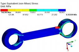
a) The stress distribution of the connecting rod
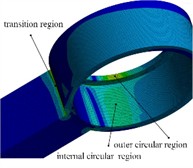
b) The main stress areas
3. Structural optimization and analysis
3.1. Structural optimization of the grinding machine
According to the modal analysis theory, it is known that the natural frequency of the grinding instrument can be altered by modifying the quality and stiffness of its entire machine structure. In the actual optimization design process, the material and processing costs resulting from the structure change of the grinding instrument must be comprehensively taken into account. The shell of the grinding instrument is fabricated from electroplated zinc sheet material and processed through sheet metal processing, bending, and welding. It is feasible to modify the structural distribution of the grinding instrument shell. As depicted in Fig. 5, the thickness of the base plate of the grinding instrument , the thickness of the bottom fold of the shell , and the side length of the sample tube adapter are chosen as the optimization design variables. The optimization objective is set to mass , the 6th-order natural frequency , and the 7th-order natural frequency . Hence, the optimal design stipulates that the total mass of the grinding machine must not exceed 30 kg, and the modal frequencies prone to resonance are restricted, demanding that the natural frequency of the 6th order be less than 30 Hz and that of the 7th order be greater than 100 Hz.
Fig. 4Optimization design variables of the grinding machine
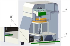
Table 1Discrete design sample data
No | / mm | / mm | / mm | / kg | / Hz | / Hz |
1 | 10.00 | 2.50 | 60.00 | 25.93 | 33.78 | 103.32 |
2 | 6.00 | 2.50 | 60.00 | 23.75 | 34.23 | 88.68 |
3 | 14.00 | 2.50 | 60.00 | 31.10 | 32.99 | 87.78 |
4 | 10.00 | 1.00 | 60.00 | 25.70 | 28.83 | 92.10 |
5 | 10.00 | 4.00 | 60.00 | 26.15 | 32.65 | 104.45 |
6 | 10.00 | 2.50 | 40.00 | 25.84 | 29.77 | 92.25 |
7 | 10.00 | 2.50 | 80.00 | 26.04 | 32.69 | 96.37 |
8 | 6.75 | 1.28 | 43.74 | 30.39 | 31.24 | 91.39 |
9 | 13.25 | 1.28 | 43.74 | 27.44 | 33.15 | 97.79 |
To obtain the relationship between the overall modal parameters, mass, and selected design variables of the grinding machine, part of sample data was obtained through experiments using the central composite design method within the design variable range. The design variables and corresponding output variables were recorded as shown in Table 1. The complete quadratic polynomial equation was used to fit the relationship between the modal optimization design variables and output variables of the grinding machine.
The internal excitation frequency range of the grinding machine varies from 0 to 90 Hz during its operation. In actual grinding processes, to ensure efficient grinding and crushing, the operating frequency of the grinding machine typically ranges from 40 to 80 Hz. By controlling the motor speed regulator, the grinding machine is enabled to swiftly pass through the low-order resonance frequency band during its startup. Through the optimization calculation, the design variables that meet the boundary conditions can be determined: 7.68 mm, 1.73 mm, 56.62 mm. Meanwhile, the sixth natural frequency of the optimized grinding machine model is 27.84 Hz, the seventh natural frequency is 104.19 Hz, and the mass is 27.39 kg, which meets the boundary conditions of the boundary optimization design.
Fig. 5Optimized modal shapes
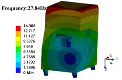
a) 6nd modal shape
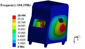
b) 7nd modal shape
3.2. Structural optimization of the connecting rod
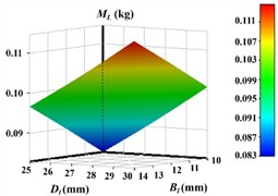
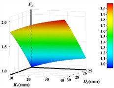
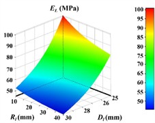
Set the curvature radius of the rear cover plate to 20, 25 mm, and 30 mm, while keeping other parameters unchanged. Import the model into ANSYS Workbench for modal analysis and comparison, and the natural frequencies of different curvature radii of the rear cover plate will be obtained, as shown in Fig. 6. Three design variables exist, encompassing the radius of the transition chamfer , the outer diameter of the ring , and the width of the link . Likewise, three optimization objectives are present, namely the mass , the safety factor , and the maximum stress . The sensitivity relationship between the design variables and the optimization objectives is depicted in Fig.7.
Fig. 6Design variables

Fig. 7The results of the sensitivity analysis
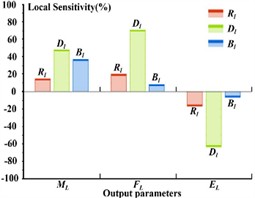
For optimization calculations, polynomial function method is used for approximate model fitting, and sequential quadratic programming algorithm is used for solving design variables. These algorithms can be reasonably selected in ANSYS Workbench. The fitted response surface function is depicted in Fig. 8. It is observable that within the stipulated range, the maximum equivalent stress of the linkage structure declines as the size of the transition radius and the outer diameter increase. The size of the outer diameter exerts a more pronounced influence on the maximum equivalent stress, which is in accordance with the sensitivity analysis results of the variables.
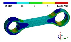
Through the optimization calculation, the design variables that meet the boundary conditions can be determined: 17.31 mm, 28.07 mm, 10.24 mm. Meanwhile,The stress and safety factor analysis results of the optimized structure are shown in Fig. 9 and Fig. 10. It can be seen that the maximum equivalent stress of the link structure under the limiting tensile condition is 59.12 MPa, which is reduced by 58.7 %. The fatigue strength of the structure has increased overall, with the minimum safety factor being 1.61, which meets the design requirements for the fatigue life.
Fig. 8Response surface models for different optimization objectives
a) Response surface of
b) Response surface of
c) Response surface of
Fig. 9Stress distribution of optimized structure
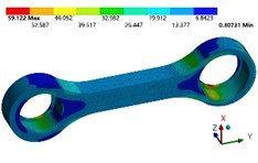
Fig. 10Fatigue safety factor of optimized structural
4. Conclusions
1) Utilizing the finite element method, the modal analysis of the main structure of the medical grinding machine was executed. To effectively evade resonance issues, the inherent frequency characteristics were optimally designed to enhance the structural layout. Consequently, the optimization goal was defined as having the sixth natural frequency less than 30 Hz, the seventh natural frequency greater than 100 Hz, and the mass less than 30 kg within the range of design variables, and the optimal solution was sought. The results demonstrate that the requirements of the optimal design can be fulfilled by matching the structural dimensions.
2) The connecting rod constitutes a crucial load-bearing component of the grinding machine. Hence, it was optimized with the stress peak value, fatigue safety coefficient, and mass serving as the optimization objectives. The outcomes reveal that the optimized connecting rod is capable of reducing the stress peak value by over 50 % without increasing the mass and fulfilling the safety coefficient requirements.
References
-
J. Huang and J. Liu, “Strength constrained topology optimization of hyperealstic structures with large deformation-induced frictionless contact,” Applied Mathematical Modelling, Vol. 126, No. 2, pp. 67–84, Feb. 2024, https://doi.org/10.1016/j.apm.2023.10.032
-
D. Zhu et al., “Noise and vibration performance of automotive disk brakes with laser-machined M-shaped grooves,” Proceedings of the Institution of Mechanical Engineers, Part D: Journal of Automobile Engineering, Vol. 237, No. 5, pp. 978–990, Apr. 2022, https://doi.org/10.1177/09544070221085972
-
H. Li, G. Wang, B. Wei, H. Liu, and W. Huang, “Improved variational mode decomposition method for vibration signal processing of flood discharge structure,” Journal of Vibration and Control, Vol. 28, No. 19-20, pp. 2556–2569, May 2021, https://doi.org/10.1177/10775463211016132
-
S. Gaygol and K. Wani, “Modal analysis of plate to analyze the effect of mass stiffeners using the Chladni plate approach,” Materials Today: Proceedings, Vol. 72, No. 3, pp. 1314–1321, Jan. 2023, https://doi.org/10.1016/j.matpr.2022.09.305
-
X. Li, D. Zhao, H. Zhai, M. Chen, and T. Zhang, “Modal analysis of circular arches in rectangular coordinate system,” Structures, Vol. 47, No. 1, pp. 2129–2137, Jan. 2023, https://doi.org/10.1016/j.istruc.2022.12.036
About this article
The authors have not disclosed any funding.
The datasets generated during and/or analyzed during the current study are available from the corresponding author on reasonable request.
The authors declare that they have no conflict of interest.
