Abstract
The response of oil tanks under dynamic loads is the key to ensuring safety, and the analysis of stiffness and strength is very necessary. Modal analysis was carried out on the oil tank to obtain the natural frequencies and vibration modes. Under specific excitation frequencies, the stress responses of the dangerous points of the front head, the rear head, the cylinder, and the transverse wave plate were calculated respectively. Three filling rates of 30 %, 50 % and 70 % were respectively selected for the structural response study, and the structural deformation and stress responses of the storage tank structure under the impact of different volumes of liquid were obtained. According to the dynamic response analysis, the structure of the front head and transverse wave plate were strengthened. It can be known from the comparison of mechanical properties that the optimized structure can significantly improve the stiffness and strength, and effectively ensure the safety of the oil tank.
Highlights
- Under specific excitation frequencies, the stress responses of the dangerous points of the front head, the rear head, the cylinder, and the transverse wave plate were calculated respectively.
- Three filling rates of 30%, 50% and 70% were respectively selected for the structural response study, and the structural deformation and stress responses of the storage tank structure under the impact of different volumes of liquid were obtained.
- According to the dynamic response analysis, the structure of the front head and transverse wave plate were strengthened.
1. Introduction
For those oil tank trucks that have been running on the road for a long time, the loads they bear are mostly alternating loads, which will cause vibration and fatigue [1, 2]. Besides, since the load of the tank truck is related to the density of the liquid in the tank. In order to avoid overloading, for liquids with higher densities, the vehicle usually does not carry a full load, which causes the tank to be impacted by the liquid in the tank again. Therefore, before the upper assembly of the tank truck is put into production and use, it is necessary to analyze the dynamic characteristics of its bearing of alternating loads [3, 4]. The load effect between the oil and the tank cannot be ignored. The oil loaded in the tank will constantly slosh, applying alternating loads to the tank structure, mainly acting on the front and rear heads of the tank, the wave plates and the bottom of the tank. If the stiffness of the model is insufficient, even if the load magnitude is much lower than the yield strength of the material, it may still lead to damage or failure of the tank structure. Modal and dynamic response analysis are the premise and basis for any complex dynamics analysis [5, 6]. In finite element analysis, both frequency response analysis and random vibration analysis are based on the results of modal analysis. In order to improve the research efficiency, modern engineering practices are increasingly inclined to adopt computer-aided engineering technology for dynamic analysis, which can reduce the cost input in the vehicle engineering design process and is a way to obtain a higher degree of data freedom. Based on the dynamic response analysis results, an effective reinforcement scheme is proposed in the article and verified by simulation to ensure the rationality of the structural optimization.
2. Modal and structural response analysis of the tank body
2.1. Modal analysis
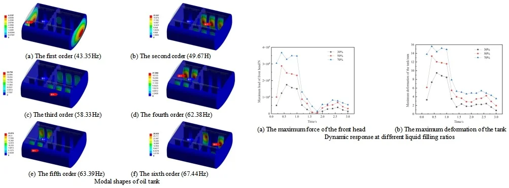
Modal analysis is the premise and foundation for any complex dynamic analysis. In finite element analysis, both frequency response analysis and random vibration analysis are based on the results of modal analysis. When analyzing the tank structure, there is a fluid medium with large mass and damping in the tank. Ignoring the mass effect of this part of the medium will lead to a large gap between the obtained modal results and the actual situation. At this time, the damping effect of the liquid needs to be considered, which is called wet modal analysis. The influence of the fluid medium in the tank on the modal frequency of the tank structure can be regarded as a fluid-solid coupling process. Therefore, a fluid-solid coupling wet modal numerical analysis model of the tank and the liquid in the tank needs to be established to obtain the natural frequency and modal shape of the liquid-containing tank more accurately. The tank body and the acoustic region need to establish a fluid-solid coupling interface for the transfer of interaction forces. Therefore, the connection position between the bottom of the tank body and the secondary beam is fixed and constrained for the constrained wet mode analysis. Since this tank body belongs to a complex assembly structure, the vibration modes in certain areas are only reflected in the higher-order modal results. The first six-order results of the wet mode analysis of the 90% liquid-filled tank body are shown in Fig. 1. It can be seen that the natural frequency differences of the vibration modes from the second order to the sixth order are very small. Due to the large number of tank body components, the stiffness differences of the longitudinal wave plates are very small due to the difference in their arrangement positions.
Fig. 1Modal shapes of oil tank
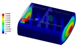
a) The first order (43.35 Hz)
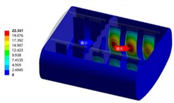
b) The second order (49.67 Hz)
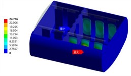
c) The third order (58.33 Hz)
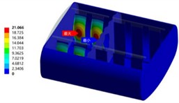
d) The fourth order (62.38 Hz)
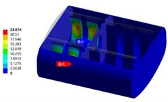
e) The fifth order (63.39 Hz)
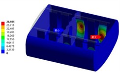
f) The sixth order (67.44 Hz)
2.2. Structural response analysis
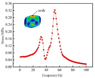
In order to obtain the frequency response corresponding to each order of frequency of the tank structure under the action of external vibration loads, it is necessary to conduct a frequency response analysis on the tank structure. The frequency response results consist of two parts: the real part and the imaginary part, corresponding to the amplitude and phase angle of the response respectively. Through the frequency response of the tank structure, the positions where the tank structure is prone to damage can also be roughly judged, and the transfer function of the corresponding node stress can be obtained as the stress tensor result during the coupling analysis. The accuracy of the transfer function of the tank structure will directly affect the accuracy of the response under random excitation. Since the frequency range of the load on the obtained tank body is basically below 100 Hz, the sweep frequency range of 1 to 100 Hz is selected, and the unit harmonic vibration acceleration excitation along the Y direction is applied at the connection position of the tank body and the frame. The amplitude is 1 m/s², and the modal damping ratio is 0.05. After conducting the frequency response analysis, the maximum principal stress distribution of the full filled tank structure at different frequencies can be obtained. One node on each of the front head, the rear head, the cylinder, and the transverse wave plate is selected as the dangerous node, as shown in Fig. 2. The analysis results show that the frequency responses at the dangerous nodes of the front and rear heads of the tank are almost the same. The slight difference is due to the different mass distributions in the front and rear compartments of the tank. The peak stress responses of the dangerous nodes of different components of the tank are located in different frequency ranges. For the fatigue analysis of complex assemblies, it cannot be limited only to a single component of the tank. Therefore, a node is selected as the dangerous node in the maximum stress area of each different component of the tank.
Fig. 2Structural response of different dangerous node
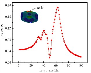
a) The front head
b) The rear head
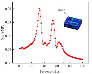
c) The cylinder
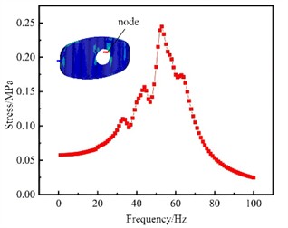
d) The transverse wave plate
2.3. Dynamic response at different filling ratios
In addition to being affected by the vibration load transmitted from the road surface, when the oil tank operates in a non-full-load state, the liquid in the tank will also shake vigorously during braking and steering. This shaking exerts additional impact forces on the head and the wave plates of the tank truck. Therefore, in the case of non-full load, a transient structural rigidity and strength analysis of the tank structure needs to be conducted first, and the safety characteristics can be analyzed based on the obtained structural responses, which is convenient to determine the dangerous node positions that need attention in advance. In order to obtain the structural deformation and stress response of the tank structure under the impact of liquids of different volumes, three filling ratios of 30 %, 50 %, and 70 % fluid model were established as in Fig. 3.
Since the center of gravity of the liquid changes with the dynamic changes of the vehicle, especially in the non-full-load state, this change is mainly manifested as the impact on the front head and the wave plates as well as the alternating load caused by the liquid sloshing. Under the braking condition, due to the presence of the transverse wave plate, the liquid in the tank can basically recover from large-amplitude sloshing to small-amplitude sloshing within 3 seconds. Therefore, a time step of 0.005 seconds was adopted and 600 steps were calculated. The pressure field under different liquid filling ratios is shown in Fig. 4. The maximum force of the front head and maximum deformation of the tank under the three filling ratios are shown in Fig. 5. It can be seen that after the braking starts, the force on the front head rapidly reaches the peak value, while the peak force arrival time of the head under a smaller filling ratio is later. After the braking ends, the liquid still produces a small amplitude of sloshing. It can be seen that due to the setting of the transverse wave plate, the liquid sloshing can end rapidly. After the braking starts, the oil in the front compartment directly impacts the front head under the action of acceleration, and the oil in the rear compartment rushes into the front compartment from the manhole of the transverse wave plate, resulting in an increase in the mass of the oil in the front compartment. The pressure on the front head and the wall of the wave plate shows a gradient distribution under the action of gravity, and the maximum pressure position is at the bottom end of the front head. Under a filling ratio of 70 %, the wall pressure reaches the peak at a braking time of 0.4 seconds. The filling ratio of 30 % reaches the peak pressure later than 50 % and 70 %, which is because at a high filling ratio, the liquid level in the rear compartment will seal the manhole of the wave plate earlier, resulting in the gas in the front compartment not being able to be discharged, and thus the oil cannot enter the front compartment, thereby causing the mass of the front compartment to stop increasing.
Fig. 3Fluid model

Fig. 4Pressure field under different liquid filling ratios
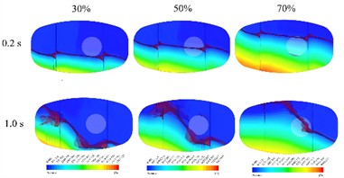
Fig. 5Dynamic response at different liquid filling ratios
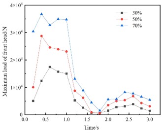
a) The maximum force of the front head
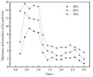
b) The maximum deformation of the tank
3. Structure optimization
3.1. Design of optimization scheme
According to the dynamic response analysis, it can be known that the structural rigidity and strength of the front head of the tank are poor during vehicle braking. The bottom and top ends of the front head and the manhole area of the transverse wave baffle are prone to fatigue damage. Therefore, it is necessary to carry out an improved design of the front head of the tank and the transverse wave baffle to enhance the structural rigidity and fatigue strength. The shapes of the head and the partition plate should be dished, and their depth should be greater than or equal to 100 mm. A structure with the same strength and stiffness, with an arc in the longitudinal direction and a straight section in the short diameter direction, can also be adopted. For the design improvement of the front head, based on the analyzed optimal head radian, and by arranging three 4 mm-thick reinforcing ribs in the vertical direction, the structural rigidity of the head in the vehicle driving direction is enhanced. The structures of the front head before and after the improvement are shown in Fig. 6(a). In addition to the large deformation of the front head, there is a stress concentration phenomenon at the manhole of the transverse wave baffle. This may not only lead to fatigue cracks in the manhole area but also cause the components made of brittle materials to fracture under static loads. Therefore, in order to avoid damage in this area, an improved design of the manhole area of the transverse wave baffle is carried out, and it is strengthened by using 3 mm annular 304 stainless steel. The structures before and after the improvement are shown in Fig. 6(b).
Fig. 6Optimization scheme

a) The front head
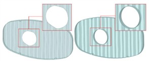
b) The transverse wave plate
3.2. Verification of stiffness and strength
After assembling the improved head and the transverse wave plate, the structural stiffness and strength of the front head of the tank and the wave plate were analyzed under the braking condition with a 70 % liquid filling ratio to determine the improvement effect. The comparison of the structural stiffness and strength of the front head before and after the improvement is shown in Fig. 7. After the improvement of the front head, its stiffness was greatly enhanced, and the deformation amount was reduced from the original maximum of 15.6 mm to 0.16 mm. The maximum equivalent stress was reduced from 167.26 MPa to 74.62 MPa, and the maximum stress distribution position was transferred from the top and bottom of the original front head to the bottom of the reinforcing rib inside the tank, while the stress values at the top and bottom of the original head were basically distributed at a relatively low level of 30 MPa.
Fig. 7The comparison of optimization effects of the front head
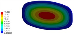
a) The deformation of initial model (unit of mm)
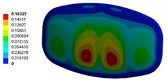
b) The deformation of optimized model (unit of mm)
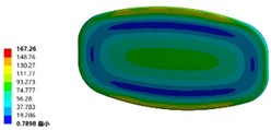
c) The stress of initial model (unit of MPa)
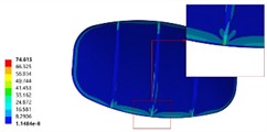
d) The stress of optimized model (unit of MPa)
The comparison of optimization effects of the transverse wave plate is shown in Fig.8. The improved wave plate has certain improvements in both stiffness and strength. The maximum equivalent stress distribution area is no longer concentrated at the manhole of the wave guard plate, but is more evenly distributed throughout the wave guard plate, and the maximum equivalent stress is only 10 MPa. The maximum deformation area has also shifted from the lower edge of the manhole to the central area of the transverse wave guard plate.
Fig. 8The comparison of optimization effects of the transverse wave plate
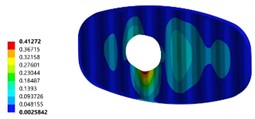
a) The deformation of initial model (unit of mm)
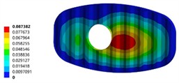
b) The deformation of optimized model (unit of mm)
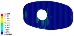
c) The stress of initial model (unit of MPa)
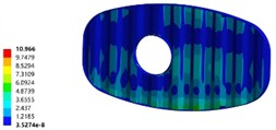
d) The stress of optimized model (unit of MPa)
4. Conclusions
1) The stiffness of the front head of the original designed tank is relatively poor. When braking at a 70 % liquid filling ratio, the maximum deformation of the front head reaches 15.6 mm, and the stress in the area of the bottom of the front head and the manhole of the transverse wave plate is relatively large.
2) After the design improvement of the manhole area of the transverse anti-wave plate and the area with larger deformation of the front head, the structural stiffness and strength have been significantly enhanced. Among them, the maximum deformation of the front head has decreased by 98 %, the maximum stress has decreased by 55 %, the maximum deformation of the transverse anti-wave plate has decreased by 78 %, and the maximum stress has decreased by 66 %.
References
-
L. Smith, O. Scott‐Emuakpor, J. Gockel, D. Celli, and P. Johnson, “Vibration bending fatigue analysis of Ti‐6Al‐4V airfoil blades repaired using additive manufacturing,” Fatigue and Fracture of Engineering Materials and Structures, Vol. 47, No. 4, pp. 1417–1430, Feb. 2024, https://doi.org/10.1111/ffe.14234
-
E. Velázquez‐Corral, J. Llumà, R. Jerez‐Mesa, V. Wagner, G. Dessein, and J. A. Travieso‐Rodriguez, “Fatigue enhancement and hardening effect through ultrasonic vibration‐assisted ball‐burnishing process on AISI 1045 steel,” Fatigue and Fracture of Engineering Materials and Structures, Vol. 47, No. 1, pp. 203–219, Nov. 2023, https://doi.org/10.1111/ffe.14180
-
W. Wu, L. Hu, and Z. Zhang, “Collaborative optimization of nonlinear hydropneumatic suspension dynamic characteristics,” Journal of Testing and Evaluation, Vol. 48, No. 2, pp. 825–837, Mar. 2020, https://doi.org/10.1520/jte20180506
-
V. Nicoletti, R. Martini, L. Amico, S. Carbonari, and F. Gara, “Operational modal analysis for supporting the retrofit design of bridges,” Ce/papers, Vol. 6, No. 5, pp. 1182–1188, Sep. 2023, https://doi.org/10.1002/cepa.2125
-
M. Sohrabifard, M. Nategh, and M. Ghazavi, “Evaluation, calibration, and modal analysis for determination of contact stiffness between workpiece and components of milling fixture,” Proceedings of the Institution of Mechanical Engineers, Part B: Journal of Engineering Manufacture, Vol. 237, No. 12, pp. 1819–1835, Nov. 2022, https://doi.org/10.1177/09544054221138165
-
Y. Wang, “Lightweight steering equipment based on prestressed modal analysis,” Journal of Vibroengineering, Vol. 26, No. 2, pp. 370–382, Mar. 2024, https://doi.org/10.21595/jve.2023.23547
About this article
The authors have not disclosed any funding.
The datasets generated during and/or analyzed during the current study are available from the corresponding author on reasonable request.
The authors declare that they have no conflict of interest.

