Abstract
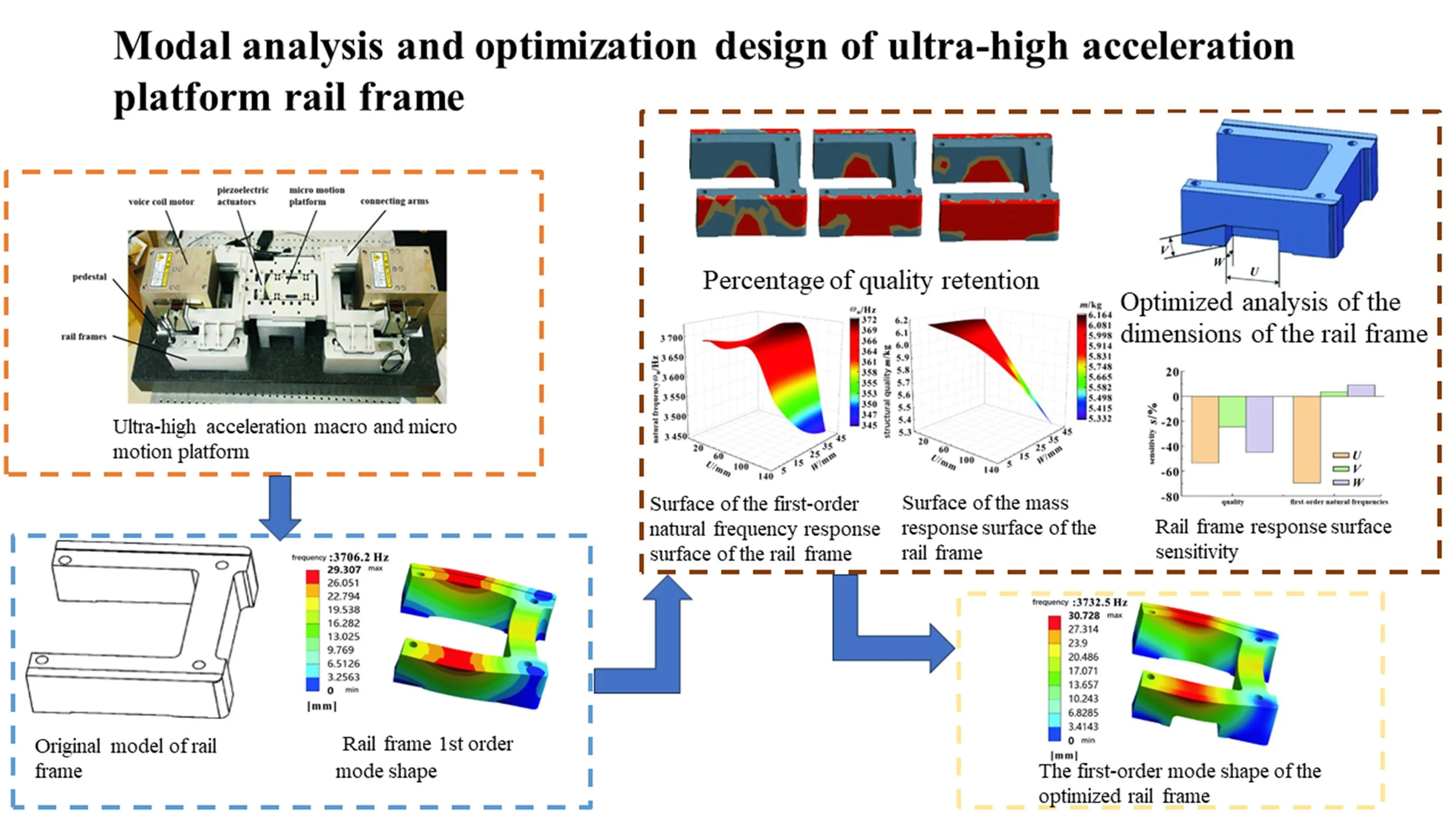
The ultra-high acceleration macro and micro motion platform has the advantages of high positioning accuracy and small error, and the key mechanism rail frame of the ultra-high acceleration macro and micro motion platform is optimized based on modal analysis to achieve the performance optimization of the platform. SolidWorks software was used to build the rail frame model, and ANSYS Workbench software was used to carry out modal analysis, topology optimization and response surface optimization, etc., so as to reduce the quality of the rail frame as much as possible under the premise of maintaining the stability of the first-order natural frequency. The results show that the optimization of the response surface meets the expected goal, the first-order natural frequency of the guide rail frame increases by 0.7 %, the mass decreases from 6.165 kg to 5.592 kg, and the change rate is 9.2 %, which achieves the purpose of lightweight.
Highlights
- Non-production line structure,This kind of research is not limited by specific production goals.
- Topology optimization uses mathematical methods to find the optimal structural design, which can minimize the amount of material used while meeting the mechanical requirements.
- By constructing a response surface model, the response surface optimization method can quickly find the best combination of test variables and the optimal response value with a small number of tests.
- Sensitivity analysis is the process of systematically changing the values of input variables, observing and documenting the impact of these changes on the model's output, in order to determine which input variables are most critical to the model or decision-making process.
1. Introduction
Explore new precision-improving technologies, such as high-precision sensors and high-precision control systems, and complete high-precision platform design to meet the needs of microelectronics manufacturing [1]. Voice coil motors for macro devices with ultra-high acceleration macro and micro motion platforms are often used in active vibration isolation systems in precision machining and other fields, which can take into account both basic vibration and direct disturbance [2]. Modal analysis is the application of system identification method in the field of engineering vibration, which is used to extract the natural frequency and mode shape of the structure, the purpose of which is to avoid resonance and harmful mode shapes when the system is working. In terms of ANSYS Workbench optimization, many scholars have carried out dimensional optimization of key components, involving many fields [3], Finite element analysis was used to optimize the weak parts of the structure of high-speed machine tools [4]. In which the parameter sensitivity analysis revealed the relationship between the optimization variables and the optimization objectives [5]. Under the optimization goal of increasing the order natural frequency and reducing the quality, the ideal optimization scheme is obtained.
2. Introduction to the structure of the guide rail frame
2.1. Ultra-high acceleration macro and micro motion platform
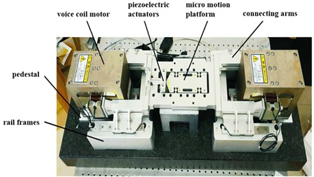
As shown in Fig. 1, the ultra-high acceleration macro and micro motion platform is a precision positioning platform that can realize nanoscale positioning. An important part of the guide rail frame and the attachment device is directly related to the transportation safety of the construction hoist, and the overall system is always under the action of dynamic load during the operation of the construction hoist, such as the dynamic excitation generated in the process of rack and pinion meshing transmission, the mobile eccentric effect of the cage on the guide rail frame, and the dynamic impact or step excitation when the cage starts and stops.
Fig. 1Ultra-high acceleration macro and micro motion platform
2.2. Design of parametric models
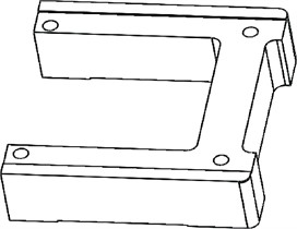
The guide rail frame is a mechanism that supports the connecting arm and makes it slide on the specified slideway, which is responsible for transmitting the direction of motion and realizing positioning. A 3D model based on the dimensions of the adjacent model was created as the basis for the design of the rail frame using SolidWorks software, and the basic model is shown in Fig. 2.
Fig. 2Original model of rail frame
3. Modal analysis of rail carriers
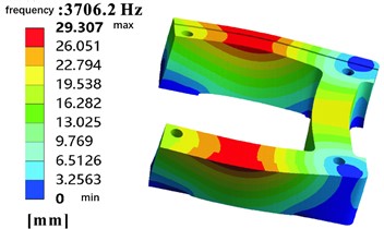
The first few natural frequencies of the structure are low, which has a great influence on the dynamic characteristics of the structure, so only the first six natural frequencies of the system structure and their corresponding mode shapes can be extracted to meet the engineering needs. The subspace iterative method is used for actual calculations in ANSYS, which can solve most modal analyses well, and has high efficiency and accuracy, and only requires very little user intervention. The 7075Al-T6 material is selected, which already exists in the ANSYS Workbench material library and can be directly called to its material parameters, as shown in Table 1. Prior to the modal analysis, the rail frame was meshed and the boundary conditions were set, where the boundary condition was that the bottom of the rail frame was fixed. The mode shape natural frequencies of the rail frame are obtained through modal analysis, the mode shape of the first order of the rail frame is shown in Fig. 3, and the natural frequencies of the first six orders of the rail frame are shown in Table 1. The first six natural frequencies and deformations of the guide rail frame structure are obtained, so the resonance and deformation of the guide rail frame structure may occur at these deformation positions. Resonance of the structure can lead to structural deformation and unpredictable behavior, affecting the safety of the structure.
Table 17075Al-T6 material properties
Material parameters | Modulus of elasticity / Pa | Poisson’s ratio | Density / (kg·m-3) |
Numeric value | 7.101 6×10¹⁰ | 0.33 | 2 793 |
Table 2The 6th-order natural frequency before the rail frame
Order | 1 | 2 | 3 | 4 | 5 | 6 |
Rail frame natural frequency / Hz | 3706.2 | 3864.7 | 4619.8 | 5799.2 | 5943.5 | 6 233.4 |
Fig. 3Rail frame 1st order mode shape
4. Rail frame optimization scheme
4.1. Rail frame topology optimization scheme
By setting different percentage of mass retention, topology optimization is actually controlling the remaining mass of the optimized structure. When the mass is retained at 70 %, the structure removes a part of the material on the basis of ensuring a certain level of quality, so that the mass of the rail frame is reduced by 21 %. At this time, the materials are mainly distributed at both ends of the rail frame, indicating that at this level of mass preservation, the stress of the structure makes more materials needed at both ends to ensure strength and stability. As the mass retention percentage decreases to 50 % and 30 %, more material is removed because the optimization algorithm further looks for areas where the material can be removed under tighter mass constraints, while ensuring that the performance of the structure is not unduly affected. The results of topology optimization are shown in Fig. 4.
Fig. 4Percentage of quality retention
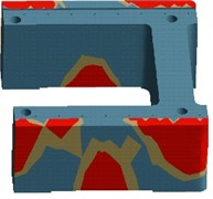
a) 70 %
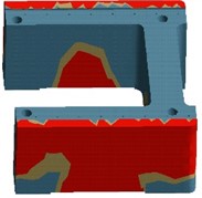
b) 50 %
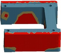
c) 30 %
Table 3Changes in quality
Mass retention percentage parameter | Original mass / kg | Reserved mass / kg |
70 % | 6.1677 | 4.8389 |
50 % | 6.1677 | 3.7094 |
30 % | 6.1677 | 2.7494 |
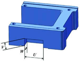
The topology optimization results show that under the premise of maintaining the original level of quality, when the optimized mass is retained to 70 %, the mass of the guide rail frame is reduced by 21 %, and the intermediate material of the outer lower part of the frame body is mainly distributed at both ends of the guide rail frame and the outer lower part of the frame body is optimized. When the optimized mass is retained at 50 %, the mass of the guide rail frame is reduced by 39.8 %, and the removed part has reached the middle position of the two ends of the guide rail frame. When the optimized mass is retained at 30 %, the mass of the rail frame is reduced by 55 %, and the removed part has been fully extended to the materials on both sides and inside of the rail frame, as shown in Table 3. Therefore, the size of these parts can be used as optimization variables for response surface optimization. Fig. 5 shows the dimensions of the optimized analysis of the rail frame, which is a visual representation of the analysis results.
Fig. 5Optimized analysis of the dimensions of the rail frame
4.2. Responsive surface optimization
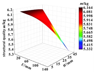
Firstly, in the design stage of the experimental site, the Central Composite design was selected as the experimental site layout method, and the Face-Centered design type was adopted. The Central Composite design is a design of experiments approach that allows for efficient fitting of response surface models with fewer experiments. The Face-Centered design type arranges experimental points in the center of the design space and on each coordinate axis, which can better capture the linear and quadratic effects of variables on the response. After setting the constraint intervals of the optimization variables reasonably, a set of sample point data is generated, and the first 7 design points are shown in Fig. 4, which can evaluate the trend of quality and natural frequency. Fig. 6 shows the resulting response surface. From Figs. 6 and 7, we can observe the influence of dimensions U and W on the first-order natural frequency and the mass of the rail. As can be seen in Fig. 6, the effect of dimension U on natural frequencies is greater than that of dimension W. It can be inferred from Fig. 7 that when the dimensions U and W increase at the same time, the mass of the rail frame decreases. This shows that sizes U and W have a similar effect on the quality of the rail frame.
To make the above conclusions more rigorous, a sensitivity analysis was performed, as shown in Fig. 8. Through sensitivity analysis, it is possible to determine which parameters are critical and need to be focused on during optimization. The effects of the first-order natural frequencies and masses in Fig. 8 are further analyzed. Under certain conditions, the dimension U is below the zero axis, and the natural frequency gradually decreases with the increase of U. The dimensions V and W are located above the zero axis, and the natural frequency gradually increases as V and W increase. However, the influence of dimension U on the natural frequency is the most significant, and the influence of dimension V on it is the least. The mass decreases with the increase of dimensions U, V, and W, with the greatest influence of size U and the least influence of size V.
Table 4Information of 7 design points before the optimization of the response surface of the rail frame
Design points | U / mm | V / mm | W / mm | Mass / kg | 1st order natural frequency / Hz |
1 | 67.5 | 37.5 | 22.5 | 5.912375079 | 3701.389652 |
2 | 5 | 37.5 | 22.5 | 6.148034454 | 3664.336732 |
3 | 36.25 | 37.5 | 22.5 | 6.030204767 | 3683.559913 |
4 | 130 | 37.5 | 22.5 | 5.676715704 | 3486.459693 |
5 | 98.75 | 37.5 | 22.5 | 5.794545392 | 3682.312494 |
6 | 67.5 | 53.75 | 22.5 | 5.912375079 | 3702.092029 |
7 | 5 | 70 | 5 | 6.162697704 | 3688.090453 |
Fig. 6Surface of the first-order natural frequency response surface of the rail frame
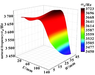
Fig. 7Surface of the mass response surface of the rail frame
Through the experimental point design and response surface design, the MOGA optimization method is adopted, which is an optimization method based on genetic algorithm, which can optimize the first-order natural frequency and reduce the mass of the guide rail frame at the same time. According to the design optimization objectives, three optimization schemes of the guide rail frame are obtained, as shown in Table 5. These solutions are obtained by considering multiple optimization objectives. Redraw the rail frame model with rounded dimensions and perform modal analysis. Fig. 9 shows the first-order modal shape of the optimized rear rail frame. As can be seen from Table 6, the optimization goal was achieved by the response surface optimization scheme, with a 0.7 % increase in the first-order natural frequency and a 9.2 % reduction in the mass of the rail frame.
Table 5Optimization scheme of response surface of rail frame
U / mm | V / mm | W / mm | 1st order natural frequency / Hz | 1st order natural frequency change rate / % | Mass / kg | Mass change rate / % | |
Scenario 1 | 84.938 | 43.89 | 39.861 | 3719.3 | 0.35 | 5.5937 | –9.2 |
Scenario 2 | 85.349 | 42.935 | 39.856 | 3719 | 0.34 | 5.5916 | –9.3 |
Scenario 3 | 85.229 | 46.039 | 39.83 | 3718.8 | 0.33 | 5.5921 | –9.2 |
Raw | 3706.2 | 6.1652 |
Fig. 8Rail frame response surface sensitivity
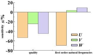
Fig. 9The first-order mode shape of the optimized rail frame
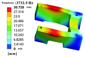
Table 6Comparison before and after optimization
1st order natural frequency / Hz | Mass / kg | |
Before optimization | 3706.2 | 6.165 |
After optimization | 3732.5 | 5.592 |
Contrast / % | 0.7 | –9.2 |
5. Conclusions
In this paper, through finite element modal analysis and optimization analysis, a comprehensive study is carried out on the rail frame of the ultra-high acceleration macro and micro motion platform. The first-order mode shape and the first-order natural frequency of the guide rail frame were obtained by establishing a finite element model, and the important parameters of structural optimization were determined. In the optimal design of the rail frame, the methods of topology optimization and response surface optimization were used, and the sensitivity analysis of the parameters was carried out. The results show that the results of response surface optimization meet the expected goals, the first-order natural frequency of the rail frame increases by 0.7 %, the mass decreases from 6.165 kg to 5.592 kg, and the change rate reaches 9.2 %.
References
-
J. Wu, X. Chen, T. Li, and L. Wang, “Optimal design of a 2-DOF parallel manipulator with actuation redundancy considering kinematics and natural frequency,” Robotics and Computer-Integrated Manufacturing, Vol. 29, No. 1, pp. 80–85, Feb. 2013, https://doi.org/10.1016/j.rcim.2012.07.005
-
H. Li, Z. Liu, and P. Zhu, “An improved multi-objective optimization algorithm with mixed variables for automobile engine hood lightweight design,” Journal of Mechanical Science and Technology, Vol. 35, No. 5, pp. 2073–2082, Apr. 2021, https://doi.org/10.1007/s12206-021-0423-5
-
P. Zhang, Z. He, C. Cui, C. Xu, and L. Ren, “An edge-computing framework for operational modal analysis of offshore wind-turbine tower,” Ocean Engineering, Vol. 287, No. 1, p. 115720, Nov. 2023, https://doi.org/10.1016/j.oceaneng.2023.115720
-
S. Shah, A. Mache, and S. Joshi, “Structural and modal analysis of gas insulated switchgear structure made up of glass-epoxy and carbon-epoxy composite materials for seismic application,” Materials Today: Proceedings, Vol. 78, No. 3, pp. 501–507, Jan. 2023, https://doi.org/10.1016/j.matpr.2022.11.209
-
I. F. Azmi, N. H. Hamid, W. I. I. W. I. Mirza, M. N. Abdul Rani, and M. A. Yunus, “Validation of modal analysis of two-storey reinforced concrete frame,” in IOP Conference Series: Materials Science and Engineering, Vol. 1062, No. 1, p. 012048, Feb. 2021, https://doi.org/10.1088/1757-899x/1062/1/012048
About this article

The authors have not disclosed any funding.
The datasets generated during and/or analyzed during the current study are available from the corresponding author on reasonable request.
The authors declare that they have no conflict of interest.
