Abstract
The finite element analysis of CFV12000 motorized spindle is carried out in the ANSYS Workbench 16.0. And the free mode experiment is carried out for the actual structure. The finite element model is modified according to the experimental results, so that the model can accurately reflect the actual situation of the motorized spindle. Then the harmonic response of the modified finite element model is analyzed to predict the dynamic characteristics in the actual machining process of the spindle. Finally, the structure of the spindle is optimized to improve its dynamic performance. The rationality of the structure design of the electric spindle is proved, which lays the foundation for the optimization of the structure of the electric spindle and the improvement of its dynamic characteristics.
1. Introduction
The electric spindle is the core functional component of CNC machine tools. It is a complex dynamic system composed of a prime mover, transmission mechanism, actuator, and control system. Compared with traditional machine tool spindles, high-speed electric spindles have the advantages of compact structure, low inertia, and high transmission efficiency. Electric spindles should not only meet high speed requirements, but also have high rigidity, good vibration resistance, and high reliability [1-2]. Therefore, analyzing the dynamic characteristics of electric spindles has become increasingly important, as it directly affects the machining efficiency and quality of the entire machine tool. With the continuous improvement of output power, speed, machining accuracy and other requirements for high-speed electric spindles in CNC machine tools, the research on the dynamic performance of high-speed electric spindles has become increasingly important [3-5]. The research on the dynamic characteristics of electric spindles mainly includes the analysis of natural vibration characteristics and dynamic response. Analyze the vibration of the spindle system in a free state, obtain its natural frequency, critical speed, and various modes of vibration, namely modal analysis; Dynamic response analysis is mainly used to determine the periodic response of linear structures under continuous cyclic loads, which can calculate the sustained dynamic characteristics of the mechanism and verify the ability of the spindle system to withstand resonance, fatigue, and other forced vibrations, namely the harmonic response analysis of the electric spindle, and the dynamic response displacement curve under high-frequency periodic forces [6-7].
This article combines finite element analysis and modal testing to analyze the dynamic characteristics of the CFV12000 electric spindle. And using the results of modal experiments to modify the finite element model, making it closer to the actual situation of the electric spindle, and conducting harmonic response analysis on the modified electric spindle model to predict the dynamic deformation of the electric spindle in actual machining.
2. Finite element analysis model for electric spindle
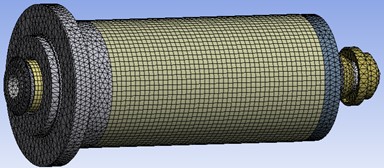
Establishing an accurate and reasonable finite element analysis model is a prerequisite for modal analysis. The spindle unit system includes a motor, cooling system, support, cutting tool system, pulse coding system, etc. The internal structure is very complex. Considering the influence of nonlinear conditions, material characteristics, stress concentration and other factors on modal analysis, simplified details and formal equivalent methods are adopted to simplify the electric spindle system as follows [9]. Build and assemble a 3D simplified model in CREO4.0, as shown in Fig. 1. Utilize ANSYS Workbench 16.0 and CREO's bi-directional parameter linkage interaction and seamless integration function to import the model into the modal analysis module. The model adopts automatic grid partitioning and achieves global control of the grid by changing the correlation and parameters of the correlation center. This analysis selected a correlation of 70 and set the correlation center to Fine. The final number of nodes divided is 291869, and the number of units is 147785, as shown in Fig. 1.
Fig. 1Grid division of the electric spindle model
This article equates the radial stiffness of the electric spindle bearing to a set of springs. In order to facilitate later spring settings, the model is preprocessed in the Design Modeler module of Workbench by adding imprints to the contact points of the springs on the model. The stiffness of the spring is 107 N/mm based on the stiffness of the front bearing provided by the enterprise. Due to the radial arrangement of two springs, the stiffness of each spring is 53.5 N/mm. The radial stiffness of the rear bearing of the main shaft is 770 N/mm, corresponding to a stiffness of 375 N/mm for each spring.
The material of the central shaft and the puller rod of the electric spindle is 20CrMnTi, the spacer parts are GCr15, the butterfly spring material in the puller system is 65Mn, and other parts are 40Cr. Then add new materials 20CrMnTi, GCr15, and 40Cr to the material library of ANSYS Workbench, and assign their density, Young’s modulus, and Poisson’s ratio according to the data in Table 1.
Table 1Material attributes
Material | Density (kg/m3) | Young’s modulus (GPa) | Poisson’s ratio |
20CrMnTi | 7860 | 212 | 0.289 |
GCr15 | 7830 | 219 | 0.3 |
40Cr | 7870 | 211 | 0.277 |
65Mn | 7810 | 206 | 0.3 |
3. Mode analysis of the high-speed electric spindle
3.1. The theoretical basis for the modal analysis
Mode analysis of the free vibration in free damping system, by solving the differential equation of motion, identify the system mode parameters, namely natural frequency, damping ratio and mode vibration parameters related to the inherent characteristics of the system itself, is an important method of structure system evaluation, estimation and design optimization. Modal analysis is the basis of other kinetic analysis (such as harmonic response analysis, transient dynamics analysis, and spectral analysis).
From a mathematical perspective [8], the generalized eigenvalues and eigenvectors of the above equation correspond to the natural frequencies and modes of vibration of the principal axis unit, respectively. Due to the fixed front end and movable rear end of the main shaft bearing of the electric spindle, the axial degrees of freedom of the spring contact point between the front end of the spindle and the spindle are limited, and the outer degrees of freedom of the bearing are all constrained. Therefore, the three degrees of freedom of the contact point between the three sets of springs and the bearing seat are limited. Since the bearing seat does not rotate relative to the rotor, the front and rear bearing seats are restricted from rotating around the spindle.
3.2. The results of the modal analysis
In the solution result, the solution term is set to be the total deformation of the cell. When the structural properties and elastic unit properties of the main axis are determined, the mode vibration properties are the only numerical solutions. Under the Modal module of ANSYS Workbench, the default method of the system is used to obtain the vibration characteristics of the first 6 order mode in the undamped free state. The natural frequency is shown in Table 2, and the vibration pattern results are shown in Fig. 2.
Table 2Natural frequency and pattern of the main spindle
Order | Frequency / Hz |
1 | 145.69 |
2 | 595.42 |
3 | 595.88 |
4 | 831.93 |
5 | 895.01 |
6 | 896.59 |
Fig. 2Front sixth order vibration pattern of the main axis

a) First-order-rotation around the -axis

b) Second-order- plane bending

c) Third order- plane bending

d) Fourth order-rotation around the axis

e) Fifth order- plane swing

f) Sixth order- plane swing
From Table 2, the natural frequencies of the second, third, fifth, and sixth orders are approximately equal. It can be seen from Fig. 3, that the second-order vibration mode of the main shaft bends first-order in the plane, and the third-order vibration mode of the main shaft bends first-order in the plane. Their vibration modes are orthogonal and can be considered as a set of multiple roots. In research and analysis, the second-order and third-order natural frequencies can be regarded as the first-order natural frequency of the main shaft. Similarly, the fourth and fifth modes of vibration are also orthogonal, and the fourth and fifth natural frequencies can be regarded as the third natural frequency of the main axis [9].
4. Experimental modal analysis of the electrical spindle
4.1. Experimental system
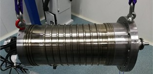
The modal experimental system consists of the tested object, excitation subsystem, data acquisition subsystem, and data processing and analysis subsystem. When conducting modal tests on a structure, there should be some definite connection between the structure and the environment. The boundary conditions for experimental modeling are consistent with the previous finite element model, namely the “free-free” boundary conditions [10]. In fact, due to the presence of gravity, it is impossible to have absolute “free-free” boundary conditions, but the electric spindle system can have the most degrees of freedom. Therefore, the experimental object is suspended with a rubber rope, and the suspension points should be placed at or close to as many modal nodes as possible. The rubber rope must be as soft as possible to prevent the rigid mode from affecting the bending mode, as shown in Fig. 3.
Fig. 3Schematic diagram of the free mode of the electric spindle
4.2. Experimental results
The operation steps of modal analysis are divided into four parts: frequency band selection, file management, modal indication, and modal identification. The analysis frequency band of the electric spindle is 0-2000 Hz. Use the cursor to select the frequency range. To perform modal analysis, a new file needs to be created to save the modal analysis results. Modal indication is responsible for calculating the modal indication function. When selecting the peak value for modal calculation, since the sensor is an accelerometer, the imaginary part is chosen for calculation. As shown in Table 3, identify the first 8 natural frequency analysis results of the electric spindle.
Table 3Results of the modal analysis
Modal | Frequency (Hz) | Damping (%) | Bandwidth (Hz) |
1 | 270.85 | 3.064 | 8.30 |
2 | 534.31 | 0.132 | 0.70 |
3 | 569.84 | 3.132 | 17.85 |
4 | 708.79 | 4.970 | 35.27 |
5 | 1022.29 | 4.828 | 49.42 |
6 | 1090.36 | 2.304 | 25.13 |
7 | 1457.95 | 2.204 | 32.15 |
8 | 1586.34 | 0.636 | 10.09 |
4.3. The harmonic response analysis of the electrical spindle
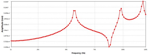
In order to study the “peak” displacement at each natural frequency of the electric spindle and analyze the dynamic stiffness at the highest speed, the frequency range of the excitation force is set to 0-1500 Hz, and the load sub step is set to 100. Set three measuring points as the front end face of the core shaft, the front end face of the rotor, and the rear end face of the core shaft, with radial displacement as the solving objective. The curves of radial displacement versus frequency for the three testing points are shown in Figs. 4-6.
According to Fig. 4, it can be seen that the radial displacement of the front end face of the spindle, which is the excitation force acting surface, increases significantly in the resonance zone. At frequencies of 500 Hz-600 Hz, the radial displacement of the front end face of the spindle increases sharply, with a maximum displacement of 130 μm, reaching the first peak. Corresponding to the first-order natural frequency of the spindle, its dynamic stiffness is 5.3 N/m, which decreases significantly; The second peak of radial displacement is at the second natural frequency, with a maximum radial displacement of 17.9 μm. Comparing Figs. 4-6, it can be seen that under the same excitation conditions, the radial displacement of the front end face of the main shaft is the largest, and it is within the working frequency range of the main shaft, that is 0-400 Hz. When subjected to low excitation frequency, the radial displacement of the three test points increases linearly with a small slope without any abrupt changes, indicating that under normal operating conditions, the dynamic stiffness decreases with the increase of rotational speed. At 400 Hz, that is, when the spindle speed is 12000 r/min, the radial displacement of the front end face of the spindle is 7.9 μm, and the dynamic stiffness is 88.6 N/μm.
Fig. 4Radial displacement-frequency curve of the front face of the electric spindle
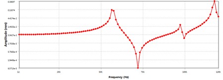
Fig. 5Radial displacement-frequency curve of the front end of the electric spindle rotor
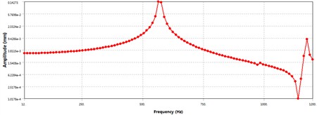
Fig. 6Radial displacement-frequency curve at the rear end surface of the electric spindle
5. Conclusions
1) The maximum speed of the CFV12000 electric spindle is 12000 r/min, which is lower than the critical speed of the spindle unit. Under normal working conditions of the spindle, it is impossible to reach the first natural frequency, that is, resonance phenomenon will not occur, ensuring the machining accuracy of the spindle.
2) The vibration mode obtained from modal analysis shows that under the same excitation conditions, the radial displacement of the rear front end face of the main shaft is the largest. Under normal working conditions, where the working frequency of the spindle is within the range of 0-400 Hz, the dynamic stiffness will decrease as the speed increases. At 400 Hz, that is, when the spindle speed is 12000 r/min, the radial displacement of the front end face of the spindle is 7.9 μm, and the dynamic stiffness is 88.6 N/μm.
3) By combining finite element analysis and modal testing, the dynamic characteristics of the electric spindle are analyzed, and the results of modal testing are used to modify the finite element model to make it closer to the actual situation of the electric spindle. The modified finite element model can also be used to optimize the structure of the electric spindle, further improving its dynamic characteristics.
References
-
J. Hao et al., “Thermal-mechanical dynamic interaction in high-speed motorized spindle considering nonlinear vibration,” International Journal of Mechanical Sciences, Vol. 240, No. 2, p. 107959, Feb. 2023, https://doi.org/10.1016/j.ijmecsci.2022.107959
-
Y. Dai, J. Pang, X. Rui, and W. Li, “Study on thermal error modeling of high-speed motorized spindle considering bearing inner ring temperature,” Case Studies in Thermal Engineering, Vol. 58, No. 6, p. 104388, Jun. 2024, https://doi.org/10.1016/j.csite.2024.104388
-
Y. Zhang, K. Li, and Q. He, “Design of cooling system and experimental research of grinding motorized spindle,” The International Journal of Advanced Manufacturing Technology, Vol. 133, No. 5-6, pp. 2145–2156, Jun. 2024, https://doi.org/10.1007/s00170-024-13789-0
-
L. Zhang, Z. Yin, K. Zhang, J. Wang, X. Wei, and L. Wang, “Effect of silver/polydopamine graphene oxide as lubricating oil additive on temperature rise and vibration of motorized spindle,” Proceedings of the Institution of Mechanical Engineers, Part C: Journal of Mechanical Engineering Science, Vol. 238, No. 5, pp. 1688–1698, Jul. 2023, https://doi.org/10.1177/09544062231187731
-
S. Kumar and D. S. Srinivasu, “Optimal number of thermal hotspots selection on motorized milling spindle to predict its thermal deformation,” Materials Today: Proceedings, Vol. 62, No. 6, pp. 3376–3385, Jan. 2022, https://doi.org/10.1016/j.matpr.2022.04.267
-
S. Sun, Y. Qiao, Z. Gao, J. Wang, and Y. Bian, “A thermal error prediction model of the motorized spindles based on ABHHO-LSSVM,” The International Journal of Advanced Manufacturing Technology, Vol. 127, No. 5-6, pp. 2257–2271, May 2023, https://doi.org/10.1007/s00170-023-11429-7
-
D. S. Truong, B.-S. Kim, and S.-K. Ro, “An analysis of a thermally affected high-speed spindle with angular contact ball bearings,” Tribology International, Vol. 157, No. 5, p. 106881, May 2021, https://doi.org/10.1016/j.triboint.2021.106881
-
Y. Tang, X. Jing, W. Li, Y. He, and J. Yao, “Analysis of influence of different convex structures on cooling effect of rectangular water channel of motorized spindle,” Applied Thermal Engineering, Vol. 198, No. 7, p. 117478, Nov. 2021, https://doi.org/10.1016/j.applthermaleng.2021.117478
-
Z. Jiang, X. Huang, M. Chang, C. Li, and Y. Ge, “Thermal error prediction and reliability sensitivity analysis of motorized spindle based on Kriging model,” Engineering Failure Analysis, Vol. 127, No. 9, p. 105558, Sep. 2021, https://doi.org/10.1016/j.engfailanal.2021.105558
-
Y. Cheng, X. Zhang, G. Zhang, W. Jiang, and B. Li, “Thermal error analysis and modeling for high-speed motorized spindles based on LSTM-CNN,” The International Journal of Advanced Manufacturing Technology, Vol. 121, No. 5-6, pp. 3243–3257, Jun. 2022, https://doi.org/10.1007/s00170-022-09563-9
About this article
This work has been funded by 2024 Ningbo Key R&D Program Project - Key Technology Research and Industrialization of Precision Guarantee for Structural Components of Domestic Large Aircraft Engines (No. 2024Z132).
The datasets generated during and/or analyzed during the current study are available from the corresponding author on reasonable request.
The authors declare that they have no conflict of interest.
