Abstract
The support frame is the main load-bearing component of crane equipment, of which modal and dynamic stress response characteristics have a critical impact on the safety and service life of the entire mechanical structure. Based on the finite element method, the support frame model was reasonably simplified and established. By arranging REB2 elements on the contact surface of the components to be connected, the rigid connection effect of the weld was realized. Through simulation calculation and modal testing, the natural frequency and vibration mode were obtained. Through modal analysis, the dynamic response analysis model was established to determine the maximum dynamic stress variation under instantaneous loading and emergency braking conditions. The results indicate that the reliability and accuracy of the finite element analysis model are high, and the maximum deviation of natural frequencies between experimental and simulation results is less than 10 %. Besides, the performance of the support frame shows good dynamic response efficiency, which proves that the mechanical structure has high stability.
Highlights
- Based on the finite element method, the support frame model was reasonably simplified and established.
- By arranging REB2 elements on the contact surface of the components to be connected, the rigid connection effect of the weld was realized.
- Through simulation calculation and modal testing, the natural frequency and vibration mode were obtained.
1. Introduction
The support frame is one of the most important core components of a crane, carrying the weight of goods and various impact loads. Its structural stability and durability play an important role in various working conditions of the crane. The deformation and fracture of crane support frames are common forms of failure, therefore, they must have sufficient strength and lifespan to cope with various loads [1, 2]. In addition, due to the various external excitation vibrations that cranes are subjected to, modal characteristics are quite crucial [3, 4]. Modal analysis is a method for studying the dynamic characteristics of structures, mainly used to analyze the natural vibration characteristics of structures. According to vibration theory, resonance may occur when the excitation frequency applied by the external environment is close to the natural frequency of the support frame [5, 6]. This resonance may not only cause fatigue damage, but also lead to deformation or even fracture, seriously affecting performance and lifespan. Compared to traditional static strength analysis, considering the stress distribution of the support frame under random dynamic loads in different directions can more comprehensively reflect the performance of motorcycles in complex environments. At present, there are few scholars who have constructed rigid flexible coupling models for crane support frames, and the vast majority of them use rigid body models. However, the rigid body model simplifies the simulation of physical entities, making it unable to capture the flexible deformations of components during actual operation, which have a significant impact on the handling stability of cranes. Therefore, based on modal analysis, a dynamic stress solution method is proposed in the article to effectively improve the calculation accuracy of dynamic characteristics.
2. Modal analysis of the crane support frame
2.1. Model establishment and simplification
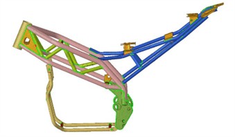
The design of the support frame has a significant impact on the operational stability of the crane, and its geometric structure and weight distribution can affect the strength and stiffness of the mechanical structure. The structure of the support frame is shown in Fig. 1, and its high-quality design can provide stable support, reduce vibration, improve steering accuracy, thereby enhancing the handling stability and seismic resistance of the equipment. The complex and sturdy spatial structure of the support frame main pipe and plate will be divided into grids using the method of extracting the middle surface. Mechanical structures contain structural features such as castings, fixed parts, rounded corners, bolt holes, installation holes, etc. These small parts have a small impact on the results of modal analysis, but extracting the midplane may lead to structural abnormalities or missing parts. To ensure the quality of the finite element model and improve the efficiency of modal analysis calculations, the model after extracting the midplane needs to be preprocessed. Simplify all chamfers with a radius less than 5mm and remove small features such as holes and gaps. Assign corresponding thickness to the punched parts and plate parts after mesh division after extracting the middle surface. Remove all protrusions with a height less than 5mm. These measures significantly simplify the grid partitioning process and improve the computational efficiency of modal analysis, while retaining the main load-bearing structures and having little impact on subsequent dynamic stress simulations.
Fig. 1Establishment of crane support frame model
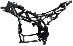
a) Physical model
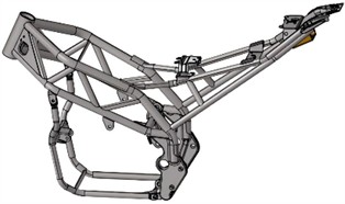
b) Simplified model
2.2. The preprocessing of the model
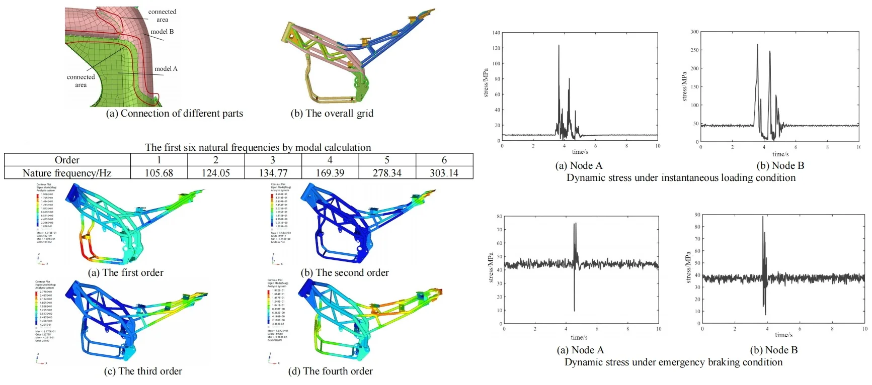
To simulate assembly with greater accuracy, two primary approaches are adopted for the connection among different elements. If the components are connected by bolts, the bonding constraint will be applied to guarantee that the contact surface does not undergo relative displacement. If the components are connected through welding, the REB2 constraint will be employed. The steel pipes and components of the support frame are generally fixed by welding, so REB2 (Rigid Element Based 2-node) elements are used to simulate the welds between different components, as shown in Fig. 2(a). REB2 is a rigid connecting element that can effectively transmit forces and displacements between components without involving any form of deformation. By arranging REB2 elements on the contact surface of the components to be connected, the rigid connection effect of the weld can be simulated. This method simplifies the modeling process of the welded joint and accurately reflects the mechanical behavior of the actual welded structure.
For thin shell structures, extracting midplanes can improve the accuracy of the model. Compared to solid elements, the middle surface has fewer degrees of freedom and simpler geometric shapes, which can improve computational efficiency. Therefore, extract midplane processing from the simplified three-dimensional model of regular tubular or plate-like structures. Divide the quadrilateral mesh with 2D shell elements and assign thickness properties. When dealing with partially irregular structures, quadrilateral element mesh is preferred. If quadrilateral mesh cannot be effectively applied in the mesh partitioning process, triangular mesh elements will be used to partition the structure. When selecting the grid cell size, the structural characteristics and complexity of the model should be considered to ensure that the selected cell size can balance computational accuracy and efficiency. The mesh division results of the finite element model are shown in Fig. 2(b).
Fig. 2Grid setting and division
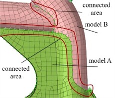
a) Connection of different parts
b) The overall grid
2.3. Modal calculation and discussion
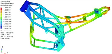
From a theoretical perspective, the initial six modal frequencies of the unconstrained free mode are all zero, which corresponds to the translation and rotation of the rotor along the X, Y, and Z axes. Through finite element calculations, the first six effective natural frequencies can be obtained, as shown in Table 1. The first four modal shapes are extracted from the results, as shown in Fig. 3. It can be seen that the first-order natural frequency is 105.68 Hz, and the largest vibration displacement occurs at the position of the dual track support beam at the bottom, with smaller resonance displacements appearing on both sides of the load-bearing position. The second and third resonance frequencies are similar, with the largest vibration displacement occurring at the rightmost support end, corresponding to the natural frequencies of 124.05 Hz and 134.77 Hz. The natural frequency of the fourth order is 169.39 Hz, and the resonance displacement occurs at the midpoint of the support frame.
Table 1The first six natural frequencies by modal calculation
Order | 1 | 2 | 3 | 4 | 5 | 6 |
Nature frequency / Hz | 105.68 | 124.05 | 134.77 | 169.39 | 278.34 | 303.14 |
Fig. 3Modal shapes
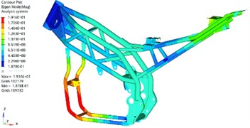
a) The first order
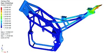
b) The second order
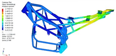
c) The third order
d) The fourth order
3. Verification of modal experiments
Experimental modal analysis is an experimental analysis method based on vibration theory, with modal parameters as the target. By conducting free modal analysis on the support structure, response signals are collected at points on the structure under the excitation force, and actual vibration characteristics data are obtained. The data is then compared with the simulation calculation results to verify the accuracy and reliability of the finite element modal analysis results and the finite element model. Given that the support structure is a welded steel pipe structure, its linear characteristics are superior. Therefore, the impact method is selected as the test excitation method. The test system consists of four parts: the LMS Test.Lab software analysis platform, the LMS SCADAS data acquisition front end, the ICP three-dimensional acceleration sensor, and the ICP impact hammer. The overall framework of the test system is shown in Fig. 4. Pre collection plays a crucial role in the data acquisition phase of modal experiments. By pre collecting, data can be recorded from before the excitation signal, which can capture the complete process of the excitation event, including the state before the excitation occurs. At the beginning of the experiment, the measurement system needs some time to stabilize, and pre collection can help identify and eliminate any bias or abnormal data that may be introduced during the system startup phase, thereby improving the accuracy and reliability of the data.
Fig. 4Modal testing scheme
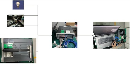
Fig. 5Power spectral density of force signal
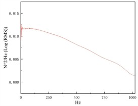
Fig. 6The first order modal shape of modal testing
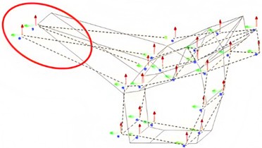
Fig. 5 shows the power spectral density of the force signal obtained during pre acquisition. By examining the frequency distribution of the excitation energy, the quality of the excitation response signal can be determined. The graph shows a decreasing curve, indicating that the response signal is relatively ideal. After pre collection, it is necessary to accurately calibrate the position of the sensor layout and the zero point and sensitivity of the signal based on the results. Formal data collection is the core stage of experimental modal analysis, which directly determines the accuracy and reliability of the experimental results. By applying dynamic excitation to the model through an impact hammer and brief tapping, the application of excitation should ensure that the main dynamic characteristics of the frame can be stimulated, and consistency and repeatability should be maintained throughout the entire testing process. To ensure the accuracy and reliability of the analysis results, low-quality data may be removed from the dataset when necessary. Through data collection and processing, the experimental modal vibration results can be obtained as shown in Fig. 6, and the test values of the first six natural frequencies are shown in Table 2. It can be seen that the accuracy of modal simulation is relatively high. The maximum deviation between experimental and simulation results is 9.48 %, corresponding to the fourth effective natural frequency.
Table 2The first six natural frequencies by modal testing
Order | 1 | 2 | 3 | 4 | 5 | 6 |
Nature frequency / Hz | 113.42 | 133.41 | 138.82 | 187.12 | 267.49 | 317.54 |
Deviation from simulation results / % | 6.82 | 7.02 | 2.92 | 9.48 | 4.06 | 4.53 |
4. Dynamic stress analysis of the crane support frame
4.1. Setting of stress analysis
In order to obtain the response results of dynamic stress, a method of converting the finite element model into a modal neutral file was selected to achieve information exchange between rigid and flexible bodies. MNF file is a key file format used for multi-body dynamics simulation, which efficiently transmits the dynamic behavior of complex structures by accurately encapsulating their modal characteristics such as natural frequencies, damping ratios, and modal shapes. By replacing rigid components with flexible bodies in the model, this file format can more accurately simulate the dynamic response and deformation of objects during the simulation process, resulting in more realistic and reliable simulation results. The MNF file contains finite element information of constructed flexible components, mainly including node information, element information, material properties, boundary conditions, and mass inertia. After defining relevant loads as shown in Fig. 7(a), the dynamic stress analysis model can be generated. Under normal steady-state working conditions, the distribution location of the maximum stress can be determined, as shown in Fig. 7(b), defined as point A and point B respectively, for dynamic stress analysis under extreme working conditions.
Fig. 7Stress analysis model
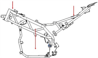
a) Position of loads
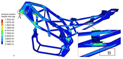
b) Cloud map of stress
4.2. Dynamic stress under limiting operating conditions
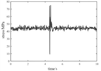
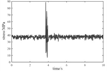
During the actual operation of the crane, extreme working conditions such as instantaneous loading and emergency braking may occasionally occur. Extreme working conditions can lead to a significant increase in vibration input, resulting in a sharp change in the load borne by the support frame. Dynamic stress under instantaneous loading condition and emergency braking condition are shown in Fig. 8 and Fig. 9. It can be seen that under different operating conditions, the maximum stress at node B is significantly greater than that at node A. From the perspective of load response efficiency, the support frame structure has a fast dynamic response rate for hard start and emergency braking, and can quickly return to a stable state, which is beneficial for the stability of crane operation.
Fig. 8Dynamic stress under instantaneous loading condition
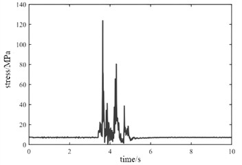
a) Node A
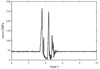
b) Node B
Fig. 9Dynamic stress under emergency braking condition
a) Node A
b) Node B
5. Conclusions
1) As an important component of crane device, the support frame is directly related to safety and service life. The various excitation loads on the support frame may result in insufficient strength or fatigue failure. Based on the structural characteristics of the support frame, Hypermesh finite element software was used to perform modal analysis on the finite element model, and verification was completed through modal experiments. The results show that the maximum error of each modal frequency is 9.48 %, and the modal shapes are in good agreement, which verifies the accuracy of the finite element model.
2) The imported modal neutral files encompass the modal information of flexible components. Consequently, stress and deformation are intercoupled, enabling a more precise determination of the dynamic response under extreme working conditions such as instant loading and emergency braking. The time-domain variation characteristics of stress at key points obtained through post-processing tools were used to verify the efficiency of the support frame structure in response to loads. The results indicate that the support frame can quickly respond to emergency braking and return to a stable state, with good safety and stability.
References
-
A. Y. Bondarenko, A. I. Likhoded, V. A. Titov, S. P. Funtikov, and A. N. Shilin, “Probabilistic correlations for resource loading regimes during transportation,” Mechanics of Solids, Vol. 59, No. 2, pp. 723–730, Sep. 2024, https://doi.org/10.1134/s0025654423601623
-
R. Zhao et al., “Lightweight optimization design and fatigue lifetime analysis for anti-rolling torsion bar of rail vehicle,” Journal of Physics: Conference Series, Vol. 2468, No. 1, p. 012052, Apr. 2023, https://doi.org/10.1088/1742-6596/2468/1/012052
-
A. Ajay Didolkar, S. Aniket Dhavale, and B. Kothavale, “Structural acoustics analysis of automobile parts by using finite element method,” Materials Today: Proceedings, Vol. 72, No. 3, pp. 1297–1301, Jan. 2023, https://doi.org/10.1016/j.matpr.2022.09.302
-
R. K. Bhamu, A. Shukla, S. C. Sharma, and S. P. Harsha, “Vibration response of steam turbine healthy and cracked blade under the stress stiffening and spin softening effects,” Proceedings of the Institution of Mechanical Engineers, Part K: Journal of Multi-body Dynamics, Vol. 236, No. 2, pp. 224–243, Feb. 2022, https://doi.org/10.1177/14644193221078656
-
M. Sohrabifard, M. Nategh, and M. Ghazavi, “Evaluation, calibration, and modal analysis for determination of contact stiffness between workpiece and components of milling fixture,” Proceedings of the Institution of Mechanical Engineers, Part B: Journal of Engineering Manufacture, Vol. 237, No. 12, pp. 1819–1835, Nov. 2022, https://doi.org/10.1177/09544054221138165
-
A. Kim, M. Doudkin, A. Ermilov, G. Kustarev, M. Sakimov, and M. Mlynczak, “Analysis of vibroexciters working process of the improved efficiency for ice breaking, construction and road machines,” Journal of Vibroengineering, Vol. 22, No. 3, pp. 465–485, May 2020, https://doi.org/10.21595/jve.2020.20446
About this article
The authors have not disclosed any funding.
The datasets generated during and/or analyzed during the current study are available from the corresponding author on reasonable request.
The authors declare that they have no conflict of interest.

