Abstract
The structural noise inside the vehicle cabin is mainly low-frequency vibration, which is closely related to the modal characteristics of the vehicle frame. The finite element method was used to simulate and calculate the body frame under free modal conditions, and the first four effective modal shapes were obtained. The calculation error of the natural frequencies was verified through modal experiments. Taking structural stiffness into account, a sound-structure coupled model was established. The suspension connection point was selected as the excitation point, and a one-way dynamic load was applied to obtain the noise and vibration responses of the front and rear rows. Based on the modal analysis results, the top-roof reinforcement scheme was adopted to verify the noise suppression effect of the structure. The results show that the optimized structure can effectively suppress structural noise, which plays an important role in improving the NVH characteristics.
Highlights
- The finite element method was used to simulate and calculate the body frame under free modal conditions, and the first four effective modal shapes were obtained.
- The calculation error of the natural frequencies was verified through modal experiments.
- Taking structural stiffness into account, a sound-structure coupled model was established.
1. Introduction
Vehicle noise is primarily categorized into structural noise and air noise. Structural noise refers to the excitation force generated by the power system, transmission system, and uneven road surface directly acting on the vehicle's body structure during operation, resulting in car frame vibration and subsequent noise radiation into the cabin through structural vibration [1, 2]. Air noise encompasses power system noise, tire noise, and wind noise transmitted directly into the cabin through various vehicle components. Structural noise predominantly occurs within the middle and low frequency band below 500 Hz, while mid- to high-frequency band noises are mainly attributed to air-related sources [3]. Therefore, structural noises are predominant in the low-frequency range [4]. The characteristics of vehicle frame modalities closely influence structural noises [5, 6]. In terms of automobile NVH (Noise Vibration Harshness) characteristics, a car's body suspension system can be likened to a vibration transmission system while its body frame functions as a radiation source for vehicle noises. Vibration excitations originating from the power system propagate through the body suspension system to stimulate vibrations in the body frame which then radiate as interior cabin noises affecting sound pressure levels perceived by drivers and passengers alike. Consequently, evaluating vehicle structure's acoustic properties necessitates studying vibration response characteristics under varying excitation frequencies. Henceforth, this paper conducts finite element analysis-based modal simulations of an entire vehicle frame model with proposed optimization schemes derived from analysis results serving as crucial foundations for enhancing NVH performance. Traditional noise reduction methods, such as adding sound-absorbing and sound-insulating materials, have a good absorption and blocking effect on high-frequency noise. Therefore, by properly laying out sound-absorbing and sound-insulating materials, it is possible to effectively suppress high-frequency noise. However, the method has little effect on low-frequency noise. Therefore, this paper proposes structural optimization to reduce low-frequency noise.
2. Simulation and testing of modal characteristics
2.1. Preprocessing of structural finite element model
The vehicle's frame structure consists of over 100 sheet metal parts, such as the roof and fenders, and the finite element modeling process is a heavy task. Therefore, it is necessary to simplify the model and standardize the finite element preprocessing workflow, otherwise it will greatly affect the work progress and the accuracy of the finite element model. Because the body structure of the vehicle is mostly made of sheet metal, its thickness is much smaller than its length and width, so in order to improve work efficiency, the body structure will be subjected to a mesh cutting process to obtain its 2D mesh. The 2D structural elements on the mesh will then be divided into elements. Hypermesh software mainly uses quadrilateral elements and triangular elements for 2D mesh division. Quadrilateral elements have one more node than triangular elements, and have a higher order of solution in the calculation, which results in higher accuracy. In the mesh division process, it is advisable to use quadrilateral elements as much as possible and keep triangular elements below 10 % to ensure the accuracy of the model. In Hypermesh software, the ACM2 (Area Contact Model 2) solder joint element is shown in Fig. 1(a), with a total of 4672 solder joints. Some panels in the body need to meet strength requirements, so screw connections are chosen. In Hypermesh software, REB2 rigid connections are selected to simulate this, and washer processing is applied to the screw connection holes to take into account the role of the washer in the screw connection. By simulating the connections, the accuracy of the simulation model can be guaranteed. It can be seen from the finite element model check of the frame structure that there are a total of 12,687,300 mesh elements, of which there are 12,154,430 quadrilateral elements and 53,287 triangular elements. The proportion of triangular elements is 4.2 %. The proportion of triangular elements meets the analysis requirements. The mass of the body structure finite element model is 353.4 kg, which is basically consistent with the actual structure mass, thus completing the preprocessing work of the finite element model and obtaining the finite element model as shown in Fig. 1(b).
Fig. 1Finite element model of the vehicle body frame
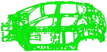
a) Solder joint element
b) 3D model
2.2. The analysis results of modal simulation
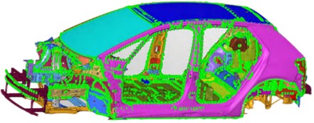
In practical terms, the body structure’s overall twisting and bending modes manifest within the low-frequency range, while its overall modal behavior is relatively subdued in the high-frequency range. Consequently, only modes below 80 Hz are considered for analysis. Solution cards for the model are configured, and the solution is obtained using a solver. The calculation results are visualized through Hyperview. In conducting free modal analysis of the body structure, as there are no constraints applied, it is observed that the first six modes in the results represent rigid-body modes and thus are disregarded. The effective first four modes capturing the body structure’s modal behavior have been selected for detailed analysis; their corresponding modal shapes can be seen in Fig. 2. It can be seen that the first modal frequency of the vehicle's white body is a local torsional mode with a frequency of 26.72 Hz, in which the front impact bar twists the most. The second modal frequency is a global first-order bending mode with a frequency of 35.31 Hz, in which the rear section of the roof and the rear floor show significant deformation. The third modal frequency is a local bending mode with a frequency of 38.59 Hz, in which the rear section of the roof and the C-pillar show significant deformation. The fourth modal frequency is a local mode of the roof with a frequency of 45.21 Hz, as can be seen from the modal shape cloud diagram, the rear end of the roof shows significant deformation.
Fig. 2Structure and modeling of hydraulic pipeline
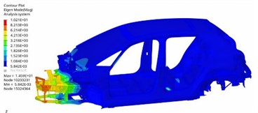
a) The firs order
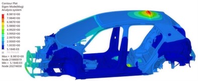
b) The second order
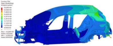
c) The third order
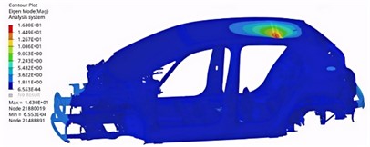
d) The fourth order
2.3. Modal test
The modal simulation calculation of the vehicle body may not reflect the actual static and dynamic characteristics of the body due to factors such as modeling accuracy and boundary conditions. Therefore, it is necessary to conduct experimental modal analysis on the vehicle body to verify the modeling accuracy. The experimental data acquisition system is provided by Siemens, and the experimental data acquisition and modal analysis software are used by LMS Test.lab. In order to ensure free boundary conditions in the experiment, the body is suspended by elastic ropes through the mounting points of the front and rear shock absorbers, as shown in Fig. 3(a). When selecting response points on the vehicle body, factors such as the frequency range, desired modal number, and key areas on the body should be taken into consideration. In order to prevent modal testing from missing modal shapes and improve the accuracy of the test results, this experiment selected a sufficient number of response points on the vehicle body structure uniformly, while excluding positions with large displacements and modal nodes. To reflect the geometric shape of the body structure, 144 response points were selected to establish a geometric model of the vehicle body structure modal test response points, as shown in Fig. 3(b).
Fig. 3Modal testing scheme
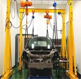
a) Installation of test equipment
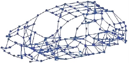
b) Test response point
The free modal shapes and frequencies of the vehicle body structure were obtained through experiments, and the experimental results were compared with the modal simulation results of the vehicle body structure, as shown in Table 1. It can be seen that the modal shapes of the body in the low frequency range are basically consistent with the modal shape cloud diagram obtained from the simulation results, and the fundamental frequencies of the body modal simulation calculation are basically consistent with the experimental results. Among them, the maximum relative error between the two’s first six eigenfrequencies appears in the second order, with a maximum relative error of 4.51 %. The simulation and experimental results are within 5 % error, which also verifies the high accuracy of the simulation model and can predict the vibration characteristics of the body structure to a certain extent, providing a basis for subsequent noise analysis and control.
Table 1Comparison of modal results
Order | Simulation value of natural frequency (Hz) | Test value of natural frequency (Hz) | Relative error (%) | Modal shapes |
1 | 26.72 | 27.3 | –2.12 | Front crash bar twist modal |
2 | 35.31 | 34.1 | 4.51 | Overall bending modal |
3 | 38.59 | 39.5 | –2.30 | Roof and C-pillar bending modal |
4 | 45.21 | 45.5 | 1.56 | Roof deformation modal |
5 | 50.56 | 51.8 | –2.39 | Overall first-order twist modal |
6 | 55.27 | 54.6 | 1.23 | Crash bar deformation modal |
3. Noise analysis and control
3.1. Establishment of acoustic-solid coupling model
If the boundary of the cabin's acoustic model is assumed to be rigid, but in reality, the wall panels around the cabin are elastic. In the case of an elastic boundary, the cabin’s acoustic modal shapes and frequencies will be subject to coupling effects, resulting in certain changes, so by analyzing the cabin's acoustic-structural coupling model, it is possible to more accurately predict the distribution of noise inside the cabin. The nodes on the coupling surface between the structural model and the acoustic model correspond, thus completing the construction of the driving cab sound-solid coupling model, as shown in Fig. 4. During vehicle operation, the power system, transmission system, and road unevenness all generate excitations, which are transmitted to the body through the attachment points. The vehicle frame vibrates under excitation and radiates noise to the driving cabin. The transmission path of noise from different attachment points is different, so the excitation point selection reference actual attachment point position on the body. However, the theory and method of studying the transmission function of different excitation points are the same. Based on the fact that the body is basically symmetrical on the left and right, the left and right front suspension attachment points are selected as the excitation point positions, as shown in Fig. 5, and a -axis unit dynamic load is applied at the excitation point position.
3.2. Noise response analysis
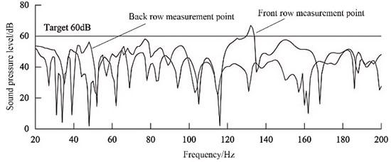
In the automotive industry standards, it is required that when the car is idling, the noise in the driver's cabin should not exceed 50 dB. When the car is traveling at a constant speed of 50 km/h, the noise in the driver’s cabin should not exceed 60 dB. When the car is traveling at a constant speed of 100 km/h, the noise in the driver's cabin should not exceed 65 dB. Therefore, by requiring standard through the regulations, this study takes the noise target of 60 dB as the standard for evaluating the noise in the driver’s cabin. The noise transfer function is an inherent property of the driver’s cabin and is only related to the transmission path, not the excitation. Therefore, by applying a unit excitation force in the direction at the excitation point, the response point noise level curve can be obtained, where the reference sound pressure is 2×10⁻⁵ Pa. The low-frequency noise inside the vehicle is mainly within 200 Hz. The analysis frequency is set to 20-200 Hz with a step size of 1 Hz, and the target value of the response point noise transfer function is set to 60 dB. The simulation results of the body attachment point noise transfer function are shown in Fig. 6. It can be seen that the noise level in the front row exceeds 60 dB, which requires structural optimization and increased stiffness to reduce noise.
Fig. 4Sound-solid coupling model
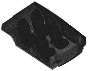
Fig. 5The excitation point positions
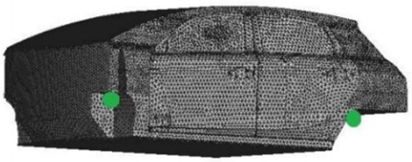
Fig. 6The harmonic response analysis results under 1g acceleration
3.3. Results of harmonic response analysis
According to the free modal analysis results, a large local modal appears in the rear part of the roof at low-order, which is likely to cause resonance when the roof is coupled with the sound chamber at a specific frequency range, resulting in poor noise characteristics of the driver’s cab. This is caused by the insufficient stiffness of the rear part of the roof structure. In order to improve the stiffness of the roof, a top cover support frame was chosen to be added to the rear part of the roof, as shown in Fig. 7.
Fig. 7Stiffness enhancement scheme
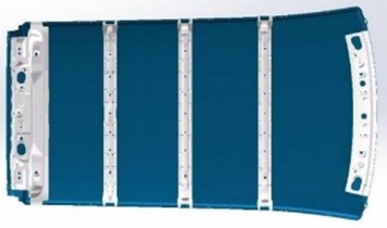
a) Initial model
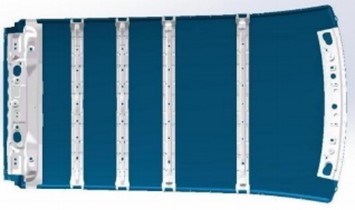
b) Reinforced model
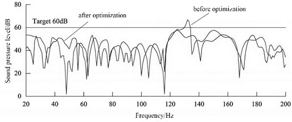
In order to minimize the impact on the overall load response of the top cover, the number of reinforced skeletons was reduced from three to four, while keeping the mechanical structure unchanged. Maintain the position of the two supporting skeletons on the right side unchanged, and add one supporting skeleton equidistant on the left side. By increasing the stiffness of the rear part of the roof support frame, the free modal response of the roof and the plate contribution in the sound-structure coupling model at the frequency range are reduced, thereby lowering the sound pressure at the response point and improving the acoustic environment of the driver’s cab. Adjust the driver's cab acoustically coupled model according to the actual optimization situation, and then conduct noise transfer function analysis on the suspension attachment points to obtain the front seat acoustic response comparison results, as shown in Fig. 8. It shows that the noise response curve after optimization meets the 60 dB target requirement in the 130-133 Hz range, and the overall acoustic environment in the driver's cab has been improved.
Fig. 8Noise optimization effect analysis (front row measurement point)
4. Conclusions
1) The inherent characteristics of the vehicle body structure do not change with the influence of external excitations. By conducting modal analysis of the vehicle body structure, we can understand the vibration characteristics of the vehicle, which can effectively avoid some structural resonance phenomena, reduce the noise in the driver’s cab, and improve the ride smoothness. Structural modal shapes can provide reference for subsequent body structure optimization, enabling the design to avoid resonance frequencies and reduce the likelihood of noise appearing later.
2) The modal analysis results can provide important basis for stiffness optimization. By optimizing the structure by increasing the number of support ribs, the natural frequency can be effectively increased without exceeding the weight limit. During the noise study, only the structure’s radiated noise is considered, and the unit excitation is used for the two attachment points. Subsequent full vehicle path analysis can be conducted by adding each path to the driver’s cabin response, which can more accurately reflect the actual noise situation of the driver’s cabin and facilitate noise reduction and vibration control.
References
-
M. M. Devarajan and G. Kumaragurparan, “Evaluation of thermal performance and vibration effects on automotive headlights for selection of heat sink geometry,” Journal of Thermal Analysis and Calorimetry, Vol. 149, No. 11, pp. 5659–5671, May 2024, https://doi.org/10.1007/s10973-024-13194-5
-
G. Paillot, S. Chesné, and D. Rémond, “Hybrid coupled damper for the mitigation of torsional vibrations and rotational irregularities in an automotive crankshaft: Concept and design subtleties,” Mechanics Based Design of Structures and Machines, Vol. 51, No. 6, pp. 3242–3259, Jun. 2023, https://doi.org/10.1080/15397734.2021.1921595
-
F. Gao, B. Yang, X. Li, and J. Wu, “Noise analysis and structural optimization of automobile scroll compressor air valve,” Applied Sciences, Vol. 14, No. 11, p. 4875, Jun. 2024, https://doi.org/10.3390/app14114875
-
V. Nicoletti, R. Martini, L. Amico, S. Carbonari, and F. Gara, “Operational modal analysis for supporting the retrofit design of bridges,” ce/papers, Vol. 6, No. 5, pp. 1182–1188, Sep. 2023, https://doi.org/10.1002/cepa.2125
-
M. Sohrabifard, M. Nategh, and M. Ghazavi, “Evaluation, calibration, and modal analysis for determination of contact stiffness between workpiece and components of milling fixture,” Proceedings of the Institution of Mechanical Engineers, Part B: Journal of Engineering Manufacture, Vol. 237, No. 12, pp. 1819–1835, Nov. 2022, https://doi.org/10.1177/09544054221138165
-
D. C. Simone, “Modal analysis through response-based FRFs: Additional modes for local diagnoses,” Journal of Sound and Vibration, Vol. 549, No. 1, pp. 101–109, Jan. 2023, https://doi.org/10.1016/ j.jsv.2023.117574
About this article

The authors have not disclosed any funding.
The datasets generated during and/or analyzed during the current study are available from the corresponding author on reasonable request.
The authors declare that they have no conflict of interest.
