Abstract
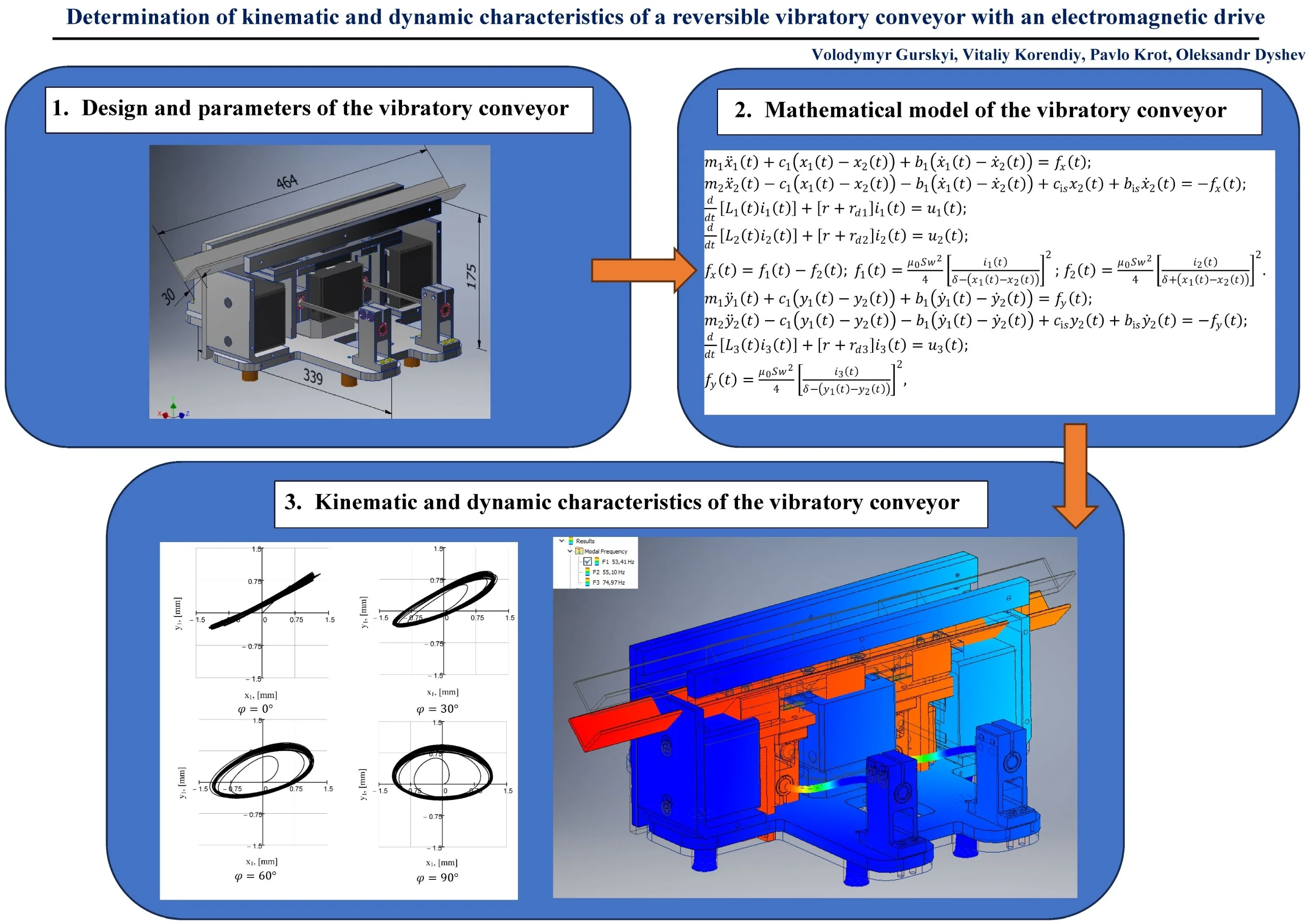
The paper considers the design parameters that must be provided during the practical implementation of small-sized reversible vibratory conveyors with an electromagnetic drive. The proposed conveyor is developed on the basis of a classical two-mass oscillatory system. Two oscillating masses are connected by symmetrically assembled round-shaped rods. In order to avoid angular (torsional) oscillations of the vibratory conveyor, the geometrical centers of mass and stiffness of the spring system are aligned at the same point. The analysis of kinematic characteristics is performed by means of numerical solving of the system of nonlinear Lagrange-Maxwell differential equations. The influence of the phase shift angle between the electromagnetic excitation of horizontal and vertical oscillations on the trajectories of the mass center of the conveying member is analyzed. The first two frequencies and forms of natural oscillations of the vibratory conveyor are determined for estimating its dynamic characteristics. The novelty of this study lies in the development of a new design of a vibratory conveyor with a controllable independent electromagnetic drive that provides the conveying reversibility and efficiency.
Highlights
- The use of an independent electromagnetic excitation in horizontal and vertical directions makes it possible to generate rectilinear and elliptical trajectories of the center of mass of the working member (conveying tray).
- In this case, in addition to changes in supply voltage and forced frequency, the trajectories are influenced by the phase shift angle between the electromagnets for horizontal and vertical oscillations.
- Considering the possible practical implementation, the use of the controlled independent electromagnetic excitation allows for experimental selecting the electrical parameters that provide optimal conditions for both transportation and energy consumption.
1. Introduction
The implementation of small-sized vibratory conveyors is most commonly carried out using AC electromagnets. In electromagnetic drives, there are no problems associated with the transition of resonant zones of oscillatory systems during the start-up regimes, which are typical for all inertial drives [1]. For low-power electromagnets, in particular for both AC and DC ones [2], [3], there are corresponding control systems allowing for changing the oscillation frequency. The use of a variable frequency is intended to eliminate the differences between the calculated and actual parameters of oscillations, to provide opportunities for independent adjustment of the oscillation amplitude and selection of optimal working regimes. Due to the operation at the near-resonance regimes, the stability of the vibratory conveyor may be disturbed, as the sensitivity to changes in loading conditions increases. Therefore, in this case, the appropriate control system is required [4]. The control systems themselves are being improved accordingly with the development of modern control tools and methods [5], [6]. Vibratory conveyors in this design are used in systems for precise feeding and dosing of different media with complex physical and mechanical properties [7], as well as in robotic assembly systems. At the same time, conveyors with directional (inclined rectilinear) oscillations of the working member using a single electromagnet have somewhat limited capabilities. More efficient ones are conveyors with adjustable elliptical trajectories and an independent excitation scheme [8]. They can also operate in a reversive regime.
2. Design and parameters of the vibratory conveyor
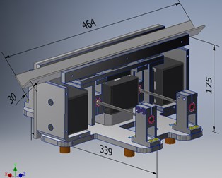
In the present paper, the authors propose an original design of the vibratory conveyor based on an enhanced two-mass oscillatory system [9], which allows for generating independent oscillations in the directions of the axes and (Fig. 1). The peculiarity of the considered design diagram is the use of two cylindrical rods being bent and allowing for the conveying member to oscillate in the plane perpendicular to their longitudinal axes. This significantly simplifies the conveyor design and ensures that the frequencies of free oscillations of the mechanical system are equal in two mutually perpendicular directions. The expediency of using two independent electromagnetic exciters was substantiated while implementing the multiple double-frequency operation regimes of vibratory systems [10]. Due to the change in the phase shift angle between the supply voltages of the electromagnets acting in the vertical and horizontal directions, the rectilinear, elliptical, or circular trajectories of the mass center of the conveyor working member can be implemented.
Fig. 1General design and overall dimensions of the vibratory conveyor
The vibratory conveyor is implemented in the form of two separately assembled upper and lower units (Fig. 2). The upper unit of the mass consists of the tray 1, electromagnets’ armatures of horizontal movement 2 and vertical movement 3, and round-shaped rods 4 for the connection with the lower unit. The lower unit of the mass contains the plate 5, electromagnets’ cores of vertical movement 6 and horizontal movement 7. The vibratory conveyor is mounted on the base through the rubber vibration isolators. The alternating current electromagnets of the same type are used to excite the oscillations in the horizontal and vertical directions. The electromagnets acting in the vertical direction are switched on using a single-ended (single-cycle) circuit, and the electromagnets of horizontal movement are switched on using a push-pull circuit.
Fig. 2Main parts of the upper and lower unit of the vibratory conveyor: 1 – tray; 2, 3 – electromagnets’ armatures; 4 – round-shaped rods; 5 – plate; 6, 7 – electromagnets’ cores
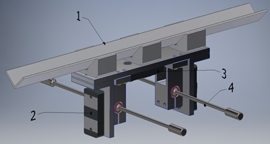
a) Upper unit
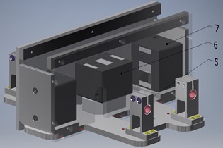
b) Lower unit
The main notations of the parameters of the vibratory system and their numerical values are presented in Fig. 3 and Table 1. The major design requirement for the implementation of a vibratory conveyor with an independent electromagnetic drive for vertical and horizontal oscillations is the geometric alignment of the mass centers and of the upper and lower units. It is also necessary that the lines of action of the electromagnets’ traction forces in the horizontal and vertical directions pass through a mutual center of mass. The two symmetrically arranged round rods must be fixed in such a way that the center of stiffness of the oscillatory system coincides with the geometric centers of mass. Meeting these design requirements prevents torsional (angular) vibrations and rotational movements of the masses. As a result, the movement of material on the working member will be uniform during the forward and reverse regimes.
Fig. 3Structural diagram and notations of basic parameters of the vibratory conveyor
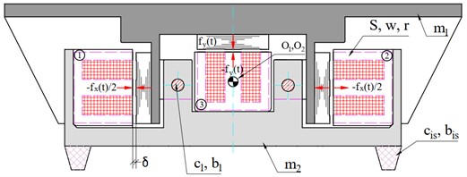
Table 1Parameters of the vibratory conveyor
Parameter | Notation | Numeric value |
Upper unit mass | 6 kg | |
Lower unit mass | 13 kg | |
Stiffness coefficient of the rods | 4.585×10⁵ N/m | |
Viscous friction (damping) coefficient of the rods | 515.9 Ns/m | |
Stiffness coefficient of the vibration isolators | 2×10³ N/m | |
Viscous friction (damping) coefficient of the vibration isolators | 200 N·s/m | |
Number of the coil windings | 650 | |
Surface area of the poles | 2.784×10⁻³ m2 | |
Nominal air gap | 3 mm | |
Active resistance of the coil | 18 Ω | |
Diode resistance in the forward direction | 0.001 Ω | |
Diode resistance in the reverse direction | 108 Ω | |
Supply voltages | , | 0…150 V |
Frequency of natural oscillations | 53.2 Hz | |
Forced (excitation) frequency | 50 Hz | |
Phase shift angle | 0…180° |
The design parameters of the vibration conveyor presented in Table 1 were obtained while performing analytical calculations to ensure its operation in a near-resonance regime (close to the second resonance). The initial parameters are the mass and length of the conveyor, and the calculated parameters are the stiffness and viscous friction (damping) coefficients. Using controlled independent electromagnetic excitation allows for experimentally selecting electrical parameters for optimal transportation speed and energy consumption. These parameters can only be determined through experimentation. This approach also allows for optimizing machine design to maximize stiffness for specific productivity and product types.
3. Mathematical model of the vibratory conveyor motion
In general, the processes and models describing the operation of electromagnetic drives are quite complex. They require experimental characteristics of hysteresis losses and magnetization curves [11]. At the preliminary stage of the study, simplified models based on idealized characteristics of the electromagnetic system can be used. Mathematically, the laws of motion of the masses and , together with the equations of electromagnetic processes, can be derived on the basis of the Lagrange-Maxwell equations.
Equations of the masses motion and electromagnetic processes in the - and -axis directions:
where , , are the inductances of electromagnet coils; 4×10⁻⁷ N/A2 is the air magnetic conductivity; is the relative magnetic conductivity of the core material; , are the laws of changing the voltages supplied to the electromagnets’ coils; , , are the idealized volt-ampere characteristics of the diodes; is the Heaviside step function, which simulates the pulsed operation of the rectifier diodes; , are the resulting traction force of the electromagnets in the horizontal and vertical directions.
4. Kinematic and dynamic characteristics of the vibratory conveyor
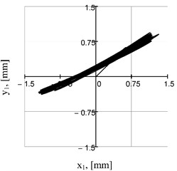
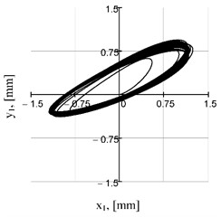
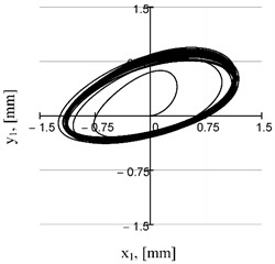
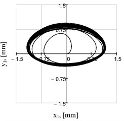
To solve the systems of nonlinear differential Eqs. (1) and (2) with impulse functions, the MathCad software and special numerical methods, in particular, Adams (BDF) and RADAUS, were used. Among the results of the numerical modeling, the main interest is raised by the trajectories of the center of mass of the working (conveying) member at different values of the phase shift angle in the range of 0...90° defining the electromagnets switching schemes (Fig. 4). Depending on the value of , we can obtain directional (rectilinear) (Fig. 4(a)) and elliptical (Fig. 4(b-d)) trajectories with different values of the ellipse axes and the angle of inclination of its main axis.
One of the conditions for the effective workability of a vibratory conveyor is to ensure the appropriate value of the first frequency of natural oscillations of the structure considered as a system with distributed parameters. It ensures the operation of the vibratory system in a near-resonance regime with a ratio of the forced frequency to the first frequency of natural oscillations of 0.96...0.98. This frequency determines the motion of separate vibrating masses as a system of absolutely rigid homogeneous bodies without any additional and parasitic deformations. In this case, the bending and shear deformations should be performed by round rods and vibration isolators. Therefore, the task of calculating the frequencies of natural oscillations is crucial at the design stage of vibratory conveying structures [12]. This is ensured by determining the appropriate rigidity of the structure and calculating the corresponding geometrical parameters of the round rods.
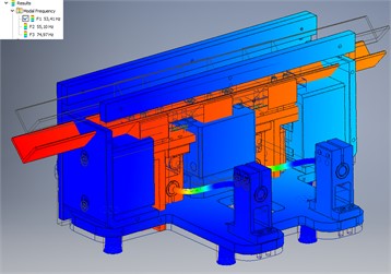
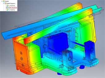
As a result of the simulation and frequency analysis performed in the Autodesk Inventor software, the value of the first natural frequency of 53.4 Hz was obtained (Fig. 5(a)). The conveyor operates at the forced frequency of 50 Hz, or within the range of frequencies up to the first natural frequency. The use of the excitation frequencies over 53.4 Hz is unacceptable, taking into account the fact that the next value of the natural frequency of 55.1 Hz (Fig. 5(b)) is determined by the resonant form of torsional vibrations. The structure may have insufficient torsional stiffness when the corresponding waveform is detected at a frequency of less than 50 Hz. In this case, the torsional vibration frequency is affected by the distance between the cylindrical rods. Therefore, it can be increased by moving the clamps of the round rods to the edges of the conveying tray. It is also necessary to change the position of the electromagnets’ cores for horizontal excitation.
Fig. 4Motion trajectories of the mass center of the upper unit at different phase shift angles
a)
b)
c)
d)
Fig. 5Simulated frequencies of natural oscillations: a) first one of 53.4 Hz; b) second one of 55.1 Hz
a)
b)
The obtained kinematic parameters of motion of the oscillating masses are further used to analyze the fatigue strength and durability of the elastic elements (round rods) [13], [14].
At the values of the phase shift angle of 90°, the trajectories become symmetrical with respect to the y-axis, which ensures reversal of the vibratory conveyor operation and change of the conveying direction. In general, to influence the motion trajectories, we can also change the power supply parameters of the electromagnets , . To improve operational efficiency, if appropriate control systems are available, it is possible to additionally adjust the excitation frequencies , . In this case, taking into account the nonlinearity and stochasticity of the vibration processes and processed media [15], it is necessary to generate more complex trajectories in terms of ensuring maximum conveying efficiency.
5. Conclusions
The general principles of designing, modeling, simulation, kinematic and dynamic analysis of the small-sized reversible vibratory conveyors with an electromagnetic drive are developed. The use of an independent electromagnetic excitation in horizontal and vertical directions makes it possible to generate rectilinear and elliptical trajectories of the center of mass of the working member (conveying tray). In this case, in addition to changes in supply voltage and forced frequency, the trajectories are influenced by the phase shift angle between the electromagnets for horizontal and vertical oscillations. Considering the possible practical implementation, the use of the controlled independent electromagnetic excitation allows for experimental selecting the electrical parameters that provide optimal conditions for both transportation and energy consumption. These conditions for a particular product or material can only be determined experimentally. Subsequently, the machine design can also be optimized in terms of ensuring the maximum stiffness for a specific productivity and type of the product to be conveyed.
References
-
N. P. Yaroshevich, O. S. Lanets, and O. M. Yaroshevych, “Slow oscillations in systems with inertial vibration exciters,” Mechanisms and Machine Science, Vol. 116, pp. 29–42, Apr. 2022, https://doi.org/10.1007/978-3-030-96603-4_3
-
O. Kachur, V. Korendiy, V. Zakharov, V. Borovets, O. Havrylchenko, and R. Palash, “Practical implementation and experimental testing of control system for vibratory lapping-polishing machine,” Vibroengineering Procedia, Vol. 50, pp. 8–14, Sep. 2023, https://doi.org/10.21595/vp.2023.23567
-
V. Korendiy, O. Kachur, V. Zakharov, I. Kuzio, I. Hurey, and R. Predko, “Experimental study of the lap motion trajectory of vibratory finishing machine,” Vibroengineering Procedia, Vol. 46, pp. 1–7, Nov. 2022, https://doi.org/10.21595/vp.2022.23002
-
A. A. Cherno, “Control of electromagnetic vibratory drive using a phase difference between current harmonics,” Journal of Automation and Information Sciences, Vol. 49, No. 7, pp. 58–76, Jan. 2017, https://doi.org/10.1615/jautomatinfscien.v49.i7.50
-
Z. V. Despotovic, A. I. Ribic, and V. M. Sinik, “Power current control of a resonant vibratory conveyor having electromagnetic drive,” Journal of Power Electronics, Vol. 12, No. 4, pp. 677–688, Jul. 2012, https://doi.org/10.6113/jpe.2012.12.4.677
-
Z. Kavaliauskas and I. Šajev, “Control of vibratory feeder device mechanical frequency using the modification of the sinusoidal supply voltage signal,” Journal of Low Power Electronics and Applications, Vol. 14, No. 1, p. 15, Mar. 2024, https://doi.org/10.3390/jlpea14010015
-
P. Mišljen, M. Matijevi´C., and Despotovi´C., “Modeling and control of bulk material flow on the electromagnetic vibratory feeder,” Automatika, Vol. 57, No. 4, pp. 936–947, Jan. 2018, https://doi.org/10.7305/automatika.2017.03.1766
-
W. Żmuda and P. Czubak, “Study of transport possibilities in the resonance zone of the new vibratory conveyor equipped with the single electro-vibrator,” Vibrations in Physical Systems, Vol. 34, No. 1, p. 20231, 2023, https://doi.org/10.21008/j.0860-6897.2023.1.16
-
Gavrylchenko, V. Gursky, O. Lanets, and Y. Shpak, “Vibrating feeder-mixer with an electromagnetic drive,” (in Ukrainian), UA Patent 87946, 2009.
-
V. Gursky, “Implementation of dual-frequency resonant vibratory machines with pulsed electromagnetic drive,” Przeglad Elektrotechniczny, Vol. 95, No. 4, pp. 43–48, Apr. 2019, https://doi.org/10.15199/48.2019.04.08
-
O. O. Cherno and A. Y. Kozlov, “Modeling of a controlled electromagnetic vibration drive with a variable resonant frequency,” Tekhnichna Elektrodynamika, Vol. 2023, No. 4, pp. 62–71, Jun. 2023, https://doi.org/10.15407/techned2023.04.062
-
Y. Wang, Z. Wang, M. Zhang, B. Xu, and Y. Song, “Dynamic characteristics analysis of a circular vibrating screen,” Vibroengineering Procedia, Vol. 48, pp. 22–28, Feb. 2023, https://doi.org/10.21595/vp.2022.23025
-
V. Gurskyi, V. Korendiy, P. Krot, R. Zimroz, O. Kachur, and N. Maherus, “On the dynamics of an enhanced coaxial inertial exciter for vibratory machines,” Machines, Vol. 11, No. 1, p. 97, Jan. 2023, https://doi.org/10.3390/machines11010097
-
V. Gursky and I. Kuzio, “Dynamic analysis of a rod vibro-impact system with intermediate supports,” Acta Mechanica et Automatica, Vol. 12, No. 2, pp. 127–134, Jun. 2018, https://doi.org/10.2478/ama-2018-0020
-
S. Schiller, D. Perchtold, and W. Steiner, “Nonlinear and chaotic dynamics of a vibratory conveying system,” Nonlinear Dynamics, Vol. 111, No. 11, pp. 9799–9814, Mar. 2023, https://doi.org/10.1007/s11071-023-08363-4
About this article

The authors have not disclosed any funding.
The datasets generated during and/or analyzed during the current study are available from the corresponding author on reasonable request.
The authors declare that they have no conflict of interest.
