Abstract
Flotation is a primary method for separating fine particles, and the growing demand for processing these particles has driven recent research efforts towards developing and designing more efficient flotation devices. Among these, the Reflux Flotation Cell (RFC) stands out as an innovative solution specifically tailored for fine particle flotation. Gas parameters are crucial factors influencing flotation and are essential indicators for evaluating flotation equipment. This study primarily investigates the gas characteristics within the RFC, including bubble size, gas holdup, and bubble surface area flux. The experimental results indicate that bubble diameters range from 0.4 to 0.8 mm, gas holdup ranges from 30 % to 50 %, and bubble surface area flux ranges from 120 to 400 s-1. These findings demonstrate that the RFC provides an optimal gas environment, conducive to effective mineral flotation.
Highlights
- RFC achieves bubble diameters of 0.4–0.8 mm and 30%–50% gas holdup.
- RFC shows a bubble surface area flux of 120–400 s⁻¹, enhancing distribution.
- RFC provides an optimal gas environment.
1. Introduction
Flotation is widely employed for the separation of fine particles, leveraging the differences in the physicochemical properties of mineral and gangue particle surfaces to effectively recover valuable minerals. As high-quality mineral resources are depleted, the quality of the ore deteriorates [1]. In recent years, there has been an increasing demand for processing fine particles and recovering valuable minerals from complex and low-grade ores. Consequently, Developing advanced flotation equipment has emerged as a primary research focus.
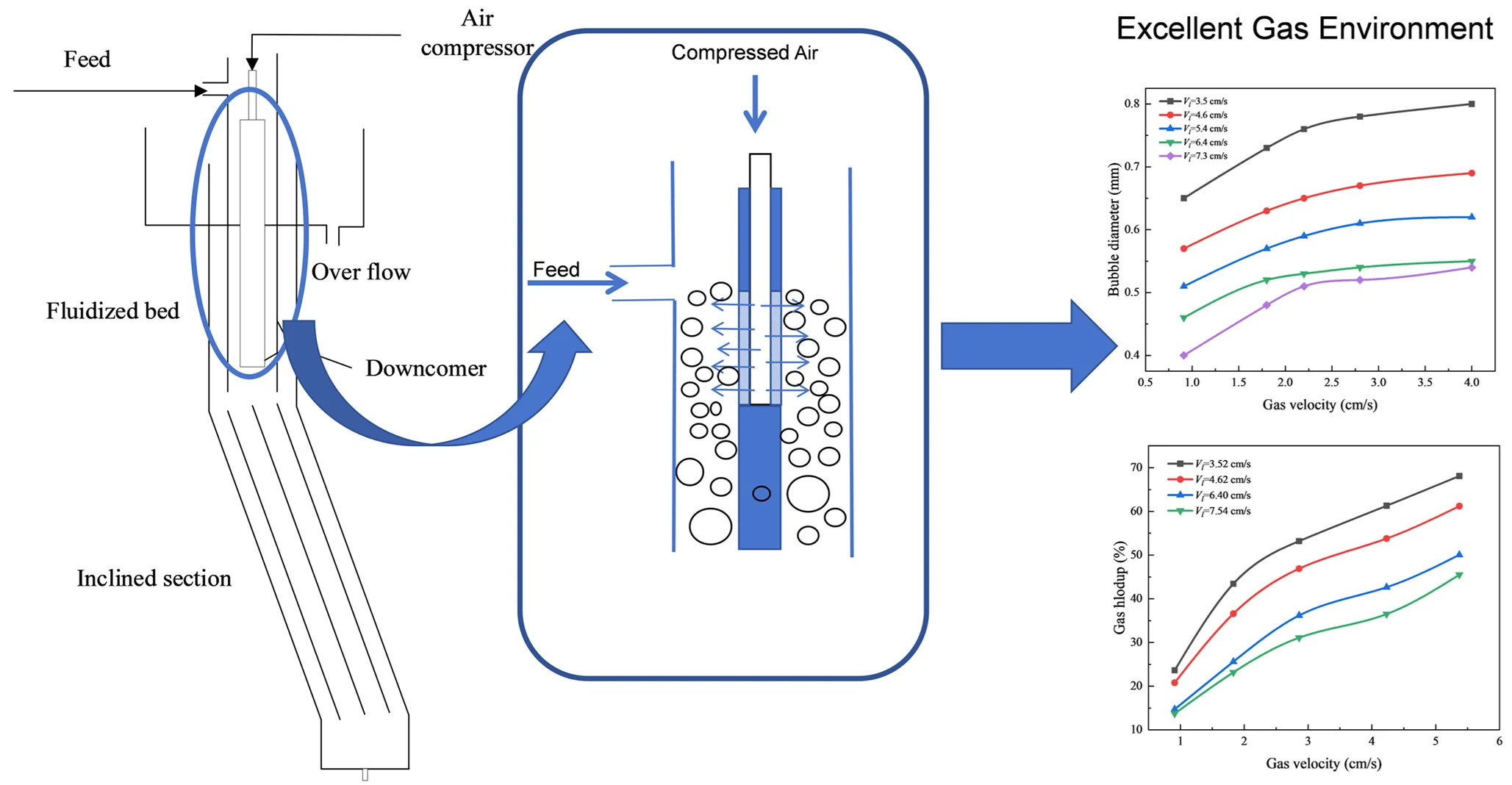
Fine particles, due to their low inertia, tend to follow streamlines, reducing the probability of bubble-particle collisions and leading to lower flotation recovery rates. Enhancing the turbulence intensity of the flow field can increase the probability of bubble-particle collisions, thereby improving the recovery rate of fine particles. The RFC, designed by the University of Newcastle, has demonstrated significant potential in processing fine particles, prompting researchers to conduct comprehensive studies on it [2]. The downcomer is the primary zone in the RFC where mineral particle mineralization occurs, utilizing a jet mineralization method [3]. As the slurry flows rapidly through the downcomer channel, a high-turbulence environment is created, promoting the shearing of bubbles into smaller sizes and increasing the collision probability between particles and bubbles. The vertical section is the primary area where bubbles and particles separate. Larger bubbles and mineralized particles move upward, while smaller bubbles and unmineralized particles move downward. As particles move downward and pass through the boundary between the vertical and inclined sections, they experience a reflux process. During this process, some hydrophobic particles and small bubbles re-enter the vertical section, where they collide with bubbles, become mineralized, and eventually rise to form the overflow [4]. The inclined channel, positioned below the vertical section, features inclined plates that increase the equipment's effective settling area. This design promotes the separation of bubbles from the slurry and the settling of fine particles. The overall design of RFC follows the concept of reactor-separator, achieving particle mineralization in a highly turbulent environment and effectively separating mineralized particles from unmineralized particles in a low turbulent environment. Gas characteristics play a crucial role in influencing the flotation process and serve as significant indicators for evaluating flotation equipment [5].
RFC is a novel flotation device that has shown significant potential in fine particle separation. Gas parameters are critical factors influencing the flotation process and serve as important indicators for evaluating flotation equipment. Therefore, this chapter focuses on analyzing and studying the bubble diameter, gas holdup, and bubble specific surface area flux within RFC. operation.
2. Experimental equipment and methods
The diagram of the experimental system is shown in Fig. 1. The RFC consists of three parts: a downcomer, a vertical section, and an inclined channel. The new downcomer structure is shown in Fig. 1(b), with the gas apparatus positioned in the middle of the downcomer. This design enhances the dispersion of the gas. The experimental system consists of three parts: a gas control system, a feed control system, and flotation equipment. Compressed air is generated by a vacuum pump, with a gas rotary flowmeter used to control and display the air intake. Liquid flow is regulated by a variable frequency drive, with an electronic turbine flowmeter accurately displaying the feed rate. The vertical section of the equipment is equipped with pressure measuring holes every 10 cm along its side. Pressure sensors monitor the pressure drop inside the equipment through these measuring hole.
Fig. 1Schematic diagram of the flotation system and downcomer structure
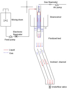
a) Schematic of the experimental setup
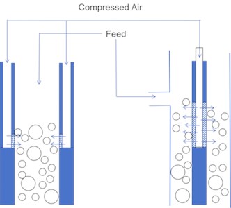
b) A comparison of downcomer design in the reflux flotation cell and new reflux flotation cell (in this paper)
This experiment focuses on capturing images of bubbles inside the vertical section. Once the system reaches a stable operating condition, a high-speed camera is used to capture images of bubbles. The bubble diameter was obtained using image processing software. This study specifically investigates the variability of gas holdup in the vertical segment, and gas holdup is determined using pressure drop measurements.
Specific Surface Area Flux is defined as the bubble surface area passing through a unit volume per unit time. The calculation formula is as follows:
where is specific surface area flux, is superficial gas velocity, is bubble diameter.
3. Results and discussion
3.1. Bubble diameter
The bubble diameter is an important parameter for evaluating bubbles. In the mineral flotation process, small bubbles can increase the collision probability between mineral particles and bubbles, thereby enhancing flotation performance [6]. Fig. 2(a) shows the variation of bubble diameter with superficial gas velocity under different liquid flow rates. It can be seen that the bubble diameter initially increases rapidly with the increase in superficial gas velocity and then increases more gradually, under different liquid velocities. At high gas velocities, the rate of increase in bubble diameter slows down with further increases in gas velocity. This phenomenon may be attributed to the RFC’s bubble generator design, which employs a 4 μm sintered titanium filter. As compressed air passes through the filter, it produces fine bubbles, maintaining a stable bubble diameter even as gas velocity increases. The liquid velocity affects the flow field inside the flotation equipment, thereby influencing the bubble diameter. As the superficial liquid velocity increases, the input energy increases, leading to a continuous decrease in bubble diameter. This observation is consistent with findings from numerous studies [7, 8].
Liquid-gas ratio refers to the volume ratio of liquid to gas within a given system. Fig. 2(b) illustrates the relationship between bubble diameter and liquid velocity under different liquid-gas ratios. From Fig. 2(b), it can be observed that the bubble diameter decreases with increasing liquid velocity. This could be due to the increased liquid velocity enhancing the shear forces within the downcomer tube, thereby supplying the energy necessary for bubble fragmentation. For liquid-gas ratios of 2 and 4, the diameter ranges from 0.62 to 0.51 mm, and at a ratio of 4, it ranges from 0.61 to 0.48 mm. When the liquid-gas ratio increases to 6, the bubble diameter significantly decreases further, ranging from 0.51 to 0.4 mm. This indicates that higher liquid-gas ratios enhance the shear rate generated by liquid flow, which is most effective in reducing bubble diameter. Bubbles in the RFC are smaller than the typical 0.5 to 2 mm range found in traditional flotation equipment.
Fig. 2Effect of bubble diameter
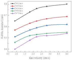
a) Liquid and gas velocity
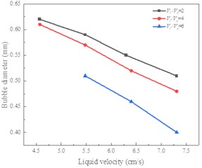
b) Liquid-to-gas ratio
3.2. Gas holdup
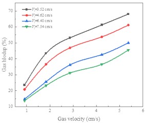
Gas holdup refers to the ratio of gas volume to the total volume within a system. Fig. 3 shows the relationship between gas holdup and gas velocity under various liquid velocity conditions. From the figure, it is evident that gas holdup increases with the increase in gas velocity. This increase in gas holdup with superficial gas velocity is likely because, as gas velocity increases, the amount of gas entering the system per unit time also increases, thus leading to a higher gas holdup. Other researchers have also observed the same trend [5], [9]. From the figure, it can be concluded that gas holdup decreases with increasing liquid velocity. This could be due to the increased overflow rate with higher liquid velocity, which enhances the upward liquid flow. As a result, bubble rise velocity increases, reducing bubble residence time and lowering gas holdup. Additionally, it can be observed from the figure that gas holdup within the RFC ranges from 30 % to 50 %, which is higher compared to the 10 % to 20 % range typically found in conventional flotation equipment.
Fig. 3Effect of gas velocity on gas holdup at different liquid velocities.
3.3. Bubble surface area flux
Bubble surface area flux is defined as the surface area of bubbles passing through a unit cross-sectional area per unit time. Fig. 4(a) shows the variation of bubble surface area flux with gas velocity under different liquid velocity conditions. From the figure, it can be observed that the bubble surface area flux increases linearly with the increase in gas velocity. Bubble surface area flux is proportional to the gas velocity, so increasing gas velocity greatly enhances bubble surface area flux. In the RFC, bubble diameter remains below 0.8 mm, resulting in a nearly linear relationship between bubble surface area flux and gas velocity.
Fig. 4(b) shows the relationship between bubble surface area flux and liquid velocity under different gas velocity conditions. From the figure, it can be seen that bubble surface area flux increases slowly with increasing liquid velocity. This may be because as liquid velocity increases, bubble diameter decreases, leading to an increase in bubble surface area flux. The bubble surface area flux ranges from 120 to 400 s-1, which is higher than the 12 to 120 s-1 typical found in conventional flotation equipment.
Fig. 4Effect of operating conditions on bubble surface area flux
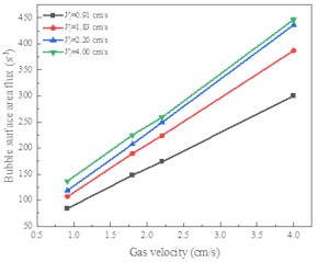
a) Gas velocity
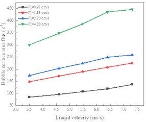
b) Liquid velocity
4. Conclusions
The RFC is a novel flotation device that has garnered widespread attention from researchers in recent years. This study primarily investigates the variations in the gas environment within the RFC under different operating conditions. The results show that the RFC provides an excellent gas environment for mineral flotation, characterized by small bubbles, high gas holdup, and high bubble surface area flux.
The bubble diameter increases with increasing gas velocity and decreases with increasing liquid velocity. At high superficial liquid velocities and low superficial gas velocities, the shear effect in the downcomer on bubbles becomes more significant. Gas holdup increases with increasing superficial gas velocity and decreases with increasing superficial liquid velocity. The RFC has a higher gas holdup, ranging from 30 % to 50 %, compared to 10 % to 20 % in conventional flotation equipment. Bubble surface area flux increases with increasing gas velocity and liquid velocity. The RFC exhibits a higher bubble surface area flux, typically ranging from 120 to 400 s-1, compared to 12 to 120 s-1 in conventional flotation equipment.
References
-
L. Bai, J. Li, B. Gao, and X. Yuan, “Study on the distribution of high ash slime in liquid-solid fluidized bed with different heights,” (in English), International Journal of Coal Preparation and Utilization, pp. 1–18, Jul. 2024, https://doi.org/10.1080/19392699.2024.2374853
-
J. Chen, W. Chimonyo, and Y. Peng, “Flotation behaviour in reflux flotation cell – A critical review,” Minerals Engineering, Vol. 181, p. 107519, May 2022, https://doi.org/10.1016/j.mineng.2022.107519
-
J. E. Dickinson, K. Jiang, and K. P. Galvin, “Fast flotation of coal at low pulp density using the Reflux Flotation Cell,” Chemical Engineering Research and Design, Vol. 101, pp. 74–81, Sep. 2015, https://doi.org/10.1016/j.cherd.2015.04.006
-
E. S. Zanin and William, “Modelling the fluidised bed in HydroFloatTM’ for improved process control,” Powder Technology: An International Journal on the Science and Technology of Wet and Dry Particulate Systems, Vol. 388, No. 1, 2021.
-
K. Bhunia, G. Kundu, and D. Mukherjee, “Gas holdup characteristics in a flotation column with different solids,” Separation Science and Technology, Vol. 52, No. 7, pp. 1298–1309, May 2017, https://doi.org/10.1080/01496395.2017.1287196
-
R.-H. Yoon, “The role of hydrodynamic and surface forces in bubble-particle interaction,” International Journal of Mineral Processing, Vol. 58, No. 1-4, pp. 129–143, Feb. 2000, https://doi.org/10.1016/s0301-7516(99)00071-x
-
M. Kukizaki and M. Goto, “Size control of nanobubbles generated from Shirasu-porous-glass (SPG) membranes,” Journal of Membrane Science, Vol. 281, No. 1-2, pp. 386–396, Sep. 2006, https://doi.org/10.1016/j.memsci.2006.04.007
-
D. Jo and S. T. Revankar, “Effect of coalescence and breakup on bubble size distributions in a two-dimensional packed bed,” Chemical Engineering Science, Vol. 65, No. 14, pp. 4231–4238, Jul. 2010, https://doi.org/10.1016/j.ces.2010.04.019
-
P. Chen, Y. Li, J. Han, L. Jing, Z. Zhang, and Y. Li, “Hydrodynamics of fluidized bed flotation column with a homogeneous binary mixture of steel balls,” (in English), Powder Technology, Vol. 429, p. 118920, Nov. 2023, https://doi.org/10.1016/j.powtec.2023.118920
About this article

The authors have not disclosed any funding.
The datasets generated during and/or analyzed during the current study are available from the corresponding author on reasonable request.
The authors declare that they have no conflict of interest.
