Abstract
In densely populated cities, the increasing popularity of railways and urban rail transit interchange hubs has led to the extensive use of land resources and raised concerns about the environment, especially the inevitable noise and vibration impact. This study aims to identify the propagation patterns of roof structure vibrations in railway complexes through experimental research, with the premise of maintaining normal train operation and safety, in order to lay a foundation for developing vibration mitigation strategies and optimizing functional layout. The results found that the train-induced vibrations are strongest at track level, but decrease as they move vertically and horizontally. Vibrations from passing trains are most noticeable within a single floor slab and beams, with minimal transmission at the base of columns.
Highlights
- Identify the propagation patterns of roof structure vibrations in railway complexes.
- Train-induced vibrations are strongest at track level.
- Vibrations from passing trains are most noticeable within a single floor slab and beams.
1. Introduction
The significance of railway transportation hubs in urban development has increasingly come to the fore, leading to their expansion in scale and land usage [1]. Presently, the land resource utilization rate of these hubs remains suboptimal, creating a stark contrast with the growing scarcity of urban land resources [2]. Comprehensive development of railway stations plays a pivotal role in enhancing urban spatial efficiency and represents a crucial avenue for achieving seamless integration between stations and cities [3].
The increasing proliferation of railway and urban rail transit interchanges in densely populated cities has not only led to significant land resource utilization but also raised environmental concerns, particularly the undeniable impact of noise and vibration [5]. A survey conducted in 2007-2008 by Switzerland revealed that 5 % of the railway lines within the Swiss Federal Railways (SBB) network exhibited unacceptable levels of vibration [5]. Additionally, a site investigation carried out by Scottish Railways indicated that 35 % of residents residing within a 100-meter radius on both sides of the railway experienced noticeable vibrations [6]. Furthermore, a substantial number of individuals living near Japan's Shinkansen line reported adverse effects from vibrations [7]. Test data from the trial period for Beijing East Suburban Ring Line conducted by the Railway Research Institute demonstrated that at speeds reaching 120 km/h, vibrations exceeded the standard limit for railway lines specified in “Environmental Vibration Standards for Urban Areas” (GB 10070-88) by 1.2 to 2.0 dB at a distance of 100 meters from the centerline [8]. Similarly, China’s Datun Railway recorded vibration levels surpassing national standards at distances as close as 30 meters from its tracks.
Therefore, it is imperative to investigate the propagation characteristics of vibrations induced by train operations within the station and its canopy structure, in order to develop targeted, cost-effective, and efficient vibration control measures for achieving sustainable urban development. This study conducts experimental research on the vibrations of a railway complex’s canopy structure with the objective of identifying vibration propagation patterns while ensuring normal train operations and safety remain unaffected, thus providing a foundation for designing vibration mitigation strategies and optimizing functional layout.
2. Measurement setup
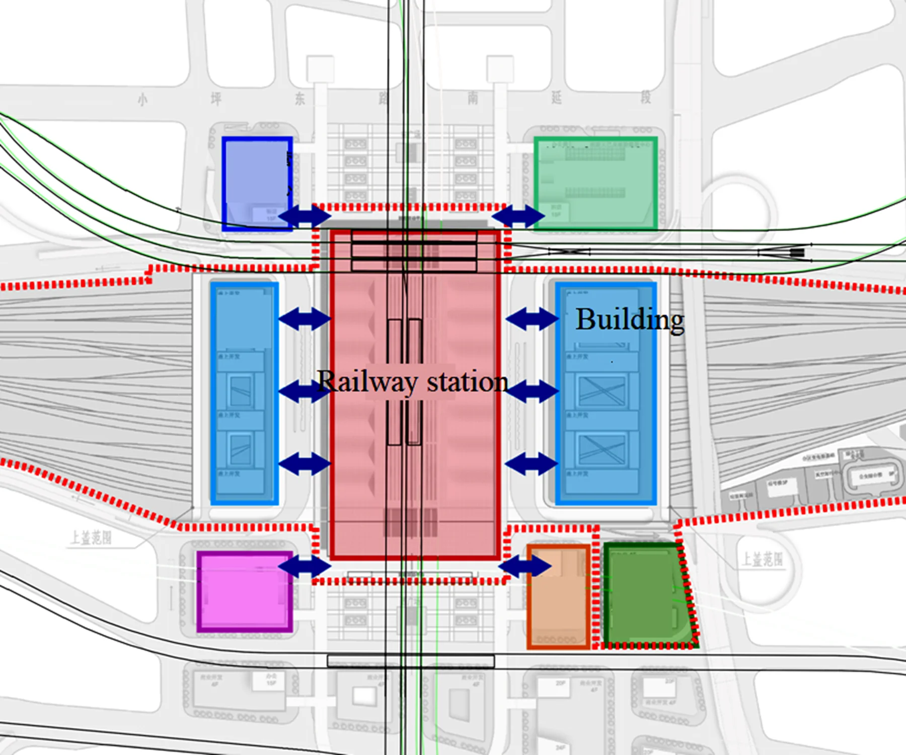
Guangzhou Baiyun Station is strategically located in the central part of Guangdong Province, at the northern edge of the Pearl River Delta, in close proximity to the lower reaches of the Pearl River and with direct connections to Shenzhen and Zhuhai. It is also adjacent to Hong Kong and Macau, making its geographical location exceptionally advantageous. The station's spatial design embodies a “people-oriented” approach, showcasing functional and systematic station building space layout through seamless transfers, spatial clarity, barrier-free access, and modern amenities. In terms of spatial utilization, the station maximizes use of the railway platform above to establish a strong connection with the station building, reflecting principles of comprehensive land development. Notably, the effective platform length measures 550 m while considering upper property development. After excluding certain uncovered areas, the roof platforms on both north and south squares cover an area of 50,400 m2 and 51,000 m2, respectively.
Fig. 1Plan view of the railway station
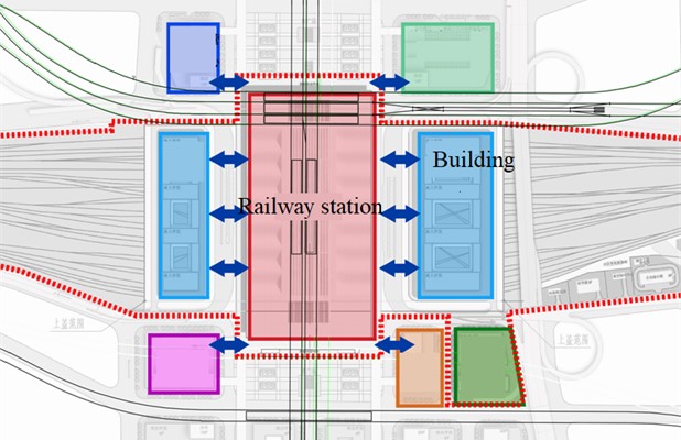
The specific arrangement of the instrument points is illustrated in Fig. 1 and Fig. 2, with distribution across the exit level, exit level mezzanine, track level, waiting level, and roof level, each serving a distinct function and bearing significance.
Fig. 2Setup of measurement along different floors (Unit: mm)
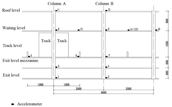
Fig. 3Setup of measurement on the waiting floor (Unit: mm)
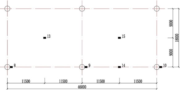
It is noteworthy that due to railway authority constraints on spatial limitations, positions for points 5 and 6 are restricted to a distance of precisely 12 m from the column center. This layout meticulously considers space utilization and measurement accuracy factors. Points 13 and 15 are situated on the floor center for precise vibration measurements while Point 14 is strategically placed within the beam structure for accurate vibration analysis.
Furthermore, the remaining points are strategically located adjacent to columns, enabling comprehensive measurement of vertical vibrations. This meticulous arrangement takes into account various considerations allowing instruments to comprehensively capture diverse vibration conditions thereby providing robust primary data essential for subsequent analytical processing.
3. Results
3.1. Vibration transmission perpendicular to the track
This section will provide a detailed analysis of the propagation pattern of vertical vibration perpendicular to the train's forward direction. According to Fig. 4, most of the data points on the exit level and waiting level indicate a trend of decreasing vibration amplitude as the distance from the source increases.
Fig. 4Vibration transmission perpendicular to the track (f: the one-third octave frequency)
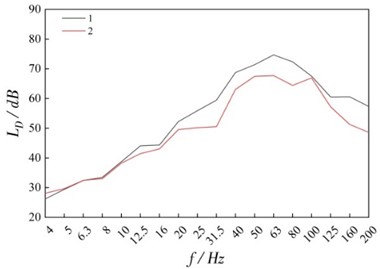
a) Exit level
b) Waiting level
For points 1 and 2, a distinct peak is observed at 63 Hz frequency. This may be due to the fact that the frequency is exactly by P2 force. The observed peak at 63 Hz may be attributed to the P2 force, a significant force generated by the subframe mass in the suspension system. In physics, subframe mass refers to the portion of mass subject to spring force, influencing its movement and resulting in vibrations of varying frequencies. When subjected to an external force such as the P2 force, the subframe mass accelerates and generates vibrations propagating at specific frequencies, with 63 Hz potentially being the most prominent peak. This phenomenon can be explained as resonance, where vibration amplitude significantly increases when the frequency of an external force closely matches the system’s natural frequency. In this case, it is possible that the frequency of the P2 force aligns with the system’s natural frequency, leading to vibration peaks at 63 Hz. At the same time, a peak is observed at around 8 Hz on waiting floor, which may be caused by the resonance of the building’s eigenfrequency in this range.
It is noteworthy that while the majority of point data adheres to the principle of diminishing vibrations with increasing distance from the source, there may be anomalous occurrences at specific locations, such as the midpoints of deck slabs and beams within elevator shafts. This could be attributed to a confluence of structural attributes and external vibrations stemming from diverse factors. Consequently, it is imperative to comprehensively consider all pertinent factors when scrutinizing vibration propagation in order to derive more precise and comprehensive conclusions.
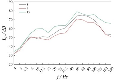
3.2. Vibration transmission along the building height
In this section, we will explore the vertical vibration propagation characteristics along the building height, as shown in Fig. 5. It is evident that vibrations exhibit a gradual decrease in both downward and upward propagation processes along the building height. However, within the 4-16 Hz frequency range, the waiting level, exit mezzanine level, and exit level (specifically at points 3, 8, and 11) demonstrate a significant amplification phenomenon compared to the track level, with an amplification ranging from 13-17 dB and a diminishing trend as frequency increases. The emergence of this amplification phenomenon may be attributed to the inherent frequencies of these layers being approximately around 8 Hz. When external vibration frequencies align closely with inherent frequencies, resonance can easily occur leading to amplified vibrations within these layers. Furthermore, vibrations in the upper deck surpass those in the waiting level within the 4-16 Hz frequency range; potentially due to hindered upward propagation compounded by an inherent frequency near 8 Hz intensifying amplification effects.
Fig. 5Vibration transmission along the building height (f: the one-third octave frequency)
a) Column A
b) Column B
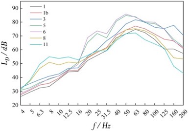
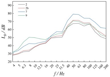
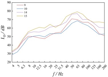
3.3. Vibration transmission within a floor slab
The positions of the slab and beam in the waiting platform, as depicted in Fig. 6, exhibit an amplification effect compared to the corresponding column side measurement points. This amplification is nearly full-band. Additionally, we observe that the central points of the slabs closely align with the measurement points on the sides of the columns.
It is important to note that such resonance and vibration amplification phenomena could impact occupant comfort. Therefore, during design and construction processes careful consideration should be given to these factors with appropriate measures implemented to minimize vibrational impacts ensuring building stability and enhancing quality of life for occupants. Additionally for existing buildings adjustments or local renovations can improve vibrational environments along with building comfort and safety.
Fig. 6Vibration transmission within a floor slab (f: the one-third octave frequency)
4. Conclusions
The objective of this study is to analyze the transmission patterns of roof structure vibrations in railway complexes through experimental research, with the goal of ensuring normal train operation and safety. This will provide a basis for developing strategies to mitigate vibrations and optimize functional layout. The conclusions can be drawn as follow:
1) The vibrations induced by the train are most pronounced at track level, with attenuation occurring as they propagate vertically and horizontally.
2) The influence of train-induced vibrations on buildings is a multifaceted matter that necessitates consideration of the structural attributes of the building, as well as the velocity and frequency of the trains, among other variables. Vibrations from passing trains exhibit maximal propagation within a single floor slab between beams and within the beams themselves, while minimal transmission occurs at the base of columns.
References
-
M. Saitoh, “On the performance of lumped parameter models with gyro-mass elements for the impedance function of a pile-group supporting a single-degree-of-freedom system,” Earthquake Engineering and Structural Dynamics, Vol. 41, pp. 623–641, 2012.
-
U. Basu, “Explicit finite element perfectly matched layer for transient three-dimensional elastic waves,” International Journal for Numerical Methods in Engineering, Vol. 77, pp. 151–176, 2009.
-
G. Kouroussis, O. Verlinden, and C. Conti, “Free field vibrations caused by high-speed lines: measurement and time domain simulation,” Soil Dynamics and Earthquake Engineering, Vol. 31, No. 4, pp. 692–707, Apr. 2011, https://doi.org/10.1016/j.soildyn.2010.11.012
-
D. Connolly, A. Giannopoulos, and M. C. Forde, “Numerical modelling of ground borne vibrations from high speed rail lines on embankments,” Soil Dynamics and Earthquake Engineering, Vol. 46, pp. 13–19, Mar. 2013, https://doi.org/10.1016/j.soildyn.2012.12.003
-
Z. Guan and Y. Wang, “CPT-based probabilistic liquefaction assessment considering soil spatial variability, interpolation uncertainty and model uncertainty,” Computers and Geotechnics, Vol. 141, p. 104504, Jan. 2022, https://doi.org/10.1016/j.compgeo.2021.104504
-
R. Müller, “Mitigation measures for open lines against vibration and ground-borne noise: a Swiss overview,” in Noise and Vibration Mitigation for Rail Transportation Systems, 2008, https://doi.org/10.1007/978-3-540-74893-9_37
-
H. J. Woodroof and M. J. Griffin, “Survey of the effect of railway induced building vibration on the community,” ISVR-TR-160, National Technical Information Service, 1987.
-
S. Yokoshima and A. Tamura, “A study on factors constituting annoyance due to Shinkansen railway vibration,” Journal of Architecture and Planning (Transactions of AIJ), Vol. 64, No. 526, pp. 1–7, Jan. 1999, https://doi.org/10.3130/aija.64.1_12
About this article

The authors have not disclosed any funding.
The datasets generated during and/or analyzed during the current study are available from the corresponding author on reasonable request.
The authors declare that they have no conflict of interest.
