Abstract
From an experimental perspective, this paper investigates the transverse vibration present in an axially travelling belt undergoing uniform motion with constant travelling speed. Application of a control of the belt speed, using Matlab, a Code Composer Studio (CCS) and the available complementary embedded tools, a stepper motor DSP control was obtained automatically by using a graphical method to establish the stepper motor movement models within a Simulink environment. By changing the tension of the belt and the rotational speed of the stepper motor, the natural frequency of the travelling belt was studied. The response waveforms, spectral content and phase diagrams were obtained by measuring the transverse vibration displacement under different conditions. A nonlinear model for the experimental moving belt system was developed and numerical solutions calculated. Subsequently, the nonlinear response behavior of this model were validated by the results of the experiment. It was shown that there were many scenarios for which the system can exhibit periodic motion, chaotic motion and beat frequency phenomena to be present and measured in the vibration of the axially travelling belt.
1. Introduction
Axially travelling belt systems are an important form of mechanical transmission, with flexibility in the belt movement and transmission layout that is not only able to transmit motion but can also transfer energy. Axially travelling belt systems are widely used in engineering devices, such as power transmission belts, plastic films, engine flat belts, paper sheets, magnetic tapes and elevator cables. Travelling belts are mostly made from viscoelastic material and their dynamics typically described and governed by nonlinear equations of motion, especially when used in large span transmission. A limitation of such devices is typically the risk of harmful large amplitude transverse nonlinear vibration, which always has the potential to be present. For example, in an automobile engine belt drive system, the transverse vibration of the travelling belt reduces the reliability of the car; in high speed manufacturing lines the tolerance and accuracy of the final manufactured thin sheet material is limited to be below speeds where critical instabilities occur in the travelling medium. Therefore, much theoretical and experimental research into the dynamics of axially travelling belt systems and its significance and practical value has been published [1-6].
Over several decades the problems and issues have remained generally unresolved and are still of current interest. Based on a Kelvin viscoelastic differential constitutive law for the belt material, different dynamic model systems of axially travelling belts have been studied extensively and many comprehensive theoretical results have been documented [1-4]. Li [1] established a nonlinear dynamic model to study an axially travelling belt and numerical simulation shows that the transverse vibration natural frequency of the travelling belt will reduce as the speed of the belt increases, whether the system behaves in a linear or nonlinear manner. A mathematical model for a travelling belt system was put forward by Kim [2] to study the forced and free vibration characteristics of a drive belt. Applying Hamilton’s principle, various parameters including the tension, length, material properties and the velocity of belt were analyzed. Being different from common belt systems, Liu [3] investigated the dynamic model of the travelling belt system with a tensioner pulley, noting that nonlinear oscillation of the belt and pulley oscillation are coupled. Zhang [4] studied the nonlinear free vibration of a viscoelastic travelling belt; the equation of motion was obtained for a travelling belt undergoing large amplitude and geometric nonlinearity by using a linear viscoelastic differential constitutive law. In contrast to the above research that mainly discussed transverse vibration, Li [5] studied the subject of an axially travelling belt that coupled the transverse and longitudinal motions showing the effect on the natural frequencies. However, for the problem of the nonlinear phenomena that includes chaotic motion, beating motion and bifurcations motion in an axially travelling belt system, significant investigations have also been reported [6-11]. Zhang [6] discussed the periodic and chaotic motion of a viscoelastic travelling belt under the case of 1:3 internal resonances and the case of 1:1 internal resonance by the Galerkin method and multiple scales. The effect of the travelling speed on a viscoelastic belts and the bifurcation behaviour and chaotic vibrations were investigated by Liu [7]. Yao also studied the bifurcations motion and chaotic dynamics for the nonlinear, non-planar oscillations of the parametrically excited viscoelastic travelling belt [8, 9]. Liu Zhang [10] later studied the chaotic motion of a six-dimensional nonlinear system for an axially travelling viscoelastic belt, the existence of jumping tracks and chaotic motions were demonstrated by numerical simulations. Compared with the theoretical studies of axially travelling belt systems, Chen [11] presented the bifurcations and chaotic motions for the nonlinear transverse vibrations of an axially accelerating viscoelastic beam, the periodic and chaotic motions that occurred for the beam were present and indicated by the numerical results.
As is known, it is difficult to measure the transverse vibration displacement during the axial movement of a belt, so there are relatively few experimental studies. In 1997, Moon and Wickert [12] used a non-contact laser interferometry method to measure vibration displacement on an axially travelling belt coated with reflective media. They found that a resonance phenomenon would appear particularly in the near-resonance region or at high running speeds. Tokoro [13] observed the generating mechanism and a method for the reduction of the response of an engine timing belt under transverse vibration, when the travelling belt meshing frequency was equal to the resonance frequency and the amplitude reaches a maximum transverse vibration. Pellicano [14] presented an experimental investigation into the effect of a pulley with slight eccentricity on the transverse vibration of a power transmission belt and the belt system in this case showed a hardening nonlinear behaviour as expected. In 1990, Molteno and Tufillaro [15] carried out a simple experiment that explained the torus doubling transition to chaos in an axially travelling string. In addition, Molteno and Tufillaro [16] studied the nonlinear characteristics of a sinusoidally forced string and observed more complex phenomena not present in the solution of the equations of motion. However, as for the relationship between the transverse nonlinear vibration, the tension and the travelling speed of the belt, little experimental work has been reported. Therefore, there are still some interesting aspects in studying such problems.
It shows that the current research status of the knowledge of the nonlinear vibration of moving string system currently are primarily theoretical model research and the experimental studies are less well covered. There is a lack of research considering the combination of theoretical and experimental results. In view of this, a vibration test device for an axial moving belt with comprehensive control functions was designed and built and an accompanying nonlinear theoretical model according to this test device is presented and solved in this paper. This experiment device has displayed a real variety of the different phenomena in the vibration of an axially moving belt, in particular, a variety of typical nonlinear phenomena, which appear in the theoretical model. The authors also attempt to explain the nonlinear phenomena in the experimental results using the theoretical model as the means of the interpretation. This paper is organized as follows. The details of the experimental system and main components are introduced in Section 2. In Section 3, an efficient way using an automatic program code generation for a stepper motor is presented and the specific experimental parameters are designed. Section 4 is devoted to showing the experimental results including the relationship between the natural frequency, tension, stepper motor speed and the response as a series of periodic motions, chaotic motion and displaying a beat frequency phenomenon. Finally, the conclusions are presented in Section 5.
2. The experimental system layout and main components
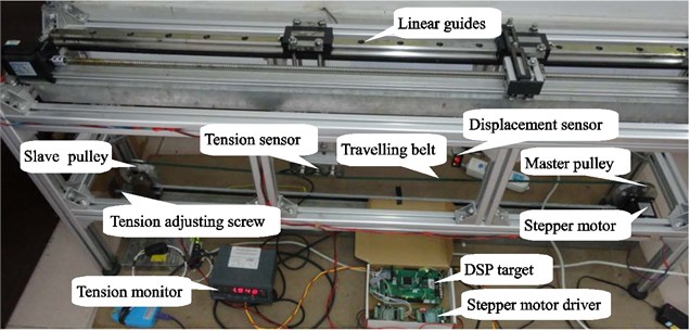
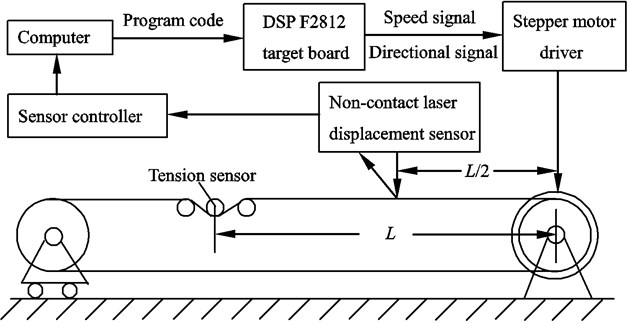
From the perspective of the experiment, this paper studies the transverse nonlinear vibration of axially travelling belt. The authors have made some improvements to the design of an earlier experimental system [17] to meet the requirement of allowing a dynamic adjustment of the belt tension, which is shown in Fig. 1. The experimental system comprises three modules: a mechanical motion module, a data acquisition module and a motion control module. The mechanical motion module comprises a bench bracket, base, axially travelling belt, linear guides, master pulley, slave pulley, the stepper motor, the tension sensor and the tension adjustment mechanism. The tension sensor, which is mounted on an axial movable holder driven by the screw nut mechanism, is located at one end of the belt, so the length of the belt can be changed as required. The slave pulley was mounted on a movable support, driven by turning the screw bolt shown in Fig. 2, so as to allow the tension of the belt to be adjusted. The value for the tension is measured by the tension sensor and is shown real time through the tension monitor in Fig. 1. By using the tension adjusting screw bolt, the tension of the travelling belt can reach the approximate fixed value for different stepper motor speeds. The acquisition module comprises a tension sensor, non-contact laser displacement sensor and sensor controller. The control module includes a computer, regulated power supply and DSP TMS320F2812 target board. This target board not only has the powerful digital signal processing ability, but also has a better time management capabilities and embedded control functions, so it is widely used in industrial control, especially used in fields of high speed and accuracy, such as intelligent instrument and meter, electric power electronic technology, etc. The principles behind the working of the entire experimental system are shown diagrammatically in Fig. 3.
Fig. 1Measurement system of the axially travelling belt and experimental devices
The distance between the master pulley and the tension sensor is represented by the distance L, the non-contact laser displacement sensor placed midway between the motor and tension sensor at a distance L/2 which measures the transverse vibration displacement at the midpoint of this section of the belt. The initial displacement of the travelling belt was produced by an electromagnet, which was under the belt and the electromagnetic excitation force was generated with a constant current applied to the electromagnet. In this experiment, the lateral positions of the master pulley and the tension sensor are fixed and the belt travels axially between these pulleys, so the experimental system can be used to investigate the vibration of the axially travelling string assuming fixed-fixed boundary conditions when the belt is modelled as a string. Compared with other existing string vibration measuring devices [12-15], this experimental device has some advanced and novel aspects: (1) the tension of the belt can be adjusted continuously in a small range and measured accurately; (2) the speed and direction of the moving belt can be changed freely within a certain range; (3) the length of the belt can be adjusted precisely and freely in the appropriate range; (4) as the laser displacement sensor is driven by the screw nut and can move axially along the belt, the transverse vibration of any point in the belt can be measured by this sensor.
The specific supporting theoretical model will be presented in Section 4.1.
Fig. 2The tension adjustment mechanism
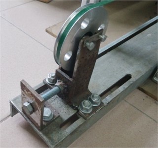
Fig. 3Schematic diagram of the set up and the principles for the experiment to reproduce the required speed control and measurement on the axially travelling belt
3. Experimental design and operation
3.1. Automatic program code generation
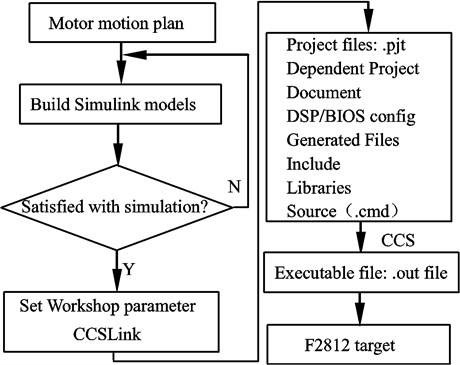
The Math Link for CCS Development Tool was developed by Math Works and TI companies. It can resolve the difficulty and time-consuming problems in programming the DSP hardware. This study used the graphical programming method successfully in realizing automatic program code generation of the stepper motor at different speeds, which avoided writing the code manually. Once the motor motion scheme has been simulated, Simulink and embedded tools generate a C language code of the model for the DSP and a CCS project is created. The stepper motor is driven and controlled by pulse width modulated (PWM) signals generated by the TMS320F2812 target board. The waveform period p of PMW for the Simulink models can be calculated by:
where θ denotes the step angle of the stepper motor, which is θ= 1.8° for this particular motor; m is the subdivision factor of the stepper motor driver, which is m= 1 in this experiment; n is the rotational speed (rpm) of the stepper motor.
The main process used is shown in Fig. 4.
Fig. 4The automatic code generation for the stepper motor
3.2. The experimental procedure and parameter specification
This experiment mainly studied two aspects. Firstly, the relationship between the natural frequency, the belt tension and the motor speed. The conditions for which the experimental results exhibiting periodic motion, the time for the periodic motion and the chaotic motion of the axially travelling belt were considered and presented in the second aspect.
Due to the manufacturing errors, slight eccentricity exists in both master pulley and slave pulley that contribute to the main sources for the excitation force acting on the system. It should be noted that a viscoelastic travelling belt was chosen instead of a metal belt for the experimental study. The viscoelastic travelling belt would be more likely to exhibit geometric deformation that is related to a series of interesting nonlinear dynamics phenomena. It is assumed that the viscoelastic material of the axially travelling belt satisfies the Kelvin model. Therefore, the differential operator determined by the viscoelastic property of the belt materials is given as follows [18]:
in which E0 is the Young’s modulus for the material of the belt; η is the dynamic viscosity of the belt.
The speed of axially travelling belt can be expressed by the following formula:
where d represents the diameter (mm) of the pulley. In order to express the relationship between the speed of travelling belt and other parameters better, this paper intends to use the stepper motor speed to represent the belt speed.
However, there are several limits in the experimental system that restricts the accuracy of the measured values. 1) To maintain the system stability, the speed of the stepper motor is limited by the range of the rotational speed of the motor from 0 to 900 rpm, i.e. 0-7 m/s, which is far smaller than the critical speed of the belt used which is given numerically by 10.41√P, where P the belt tension (see table 1); 2) The driving device can easily cause the vibration of the experimental system when the belt is stretched or shortened and it is disadvantageous for measuring the transverse vibration displacement; 3) The value of the measured tension by the tension sensor is not the real value for the whole belt, for the tension is time-varying with different values at different positions along the belt.
To ensure the accuracy and the repeatability of the experiment, this study followed the following principles:
1) The non-contact laser displacement sensor is required to be set to zero before measuring the dynamic displacement vibration at the midpoint of the travelling belt, as shown in Fig. 3.
2) To avoid the influence of initial instable conditions, the data acquisition was initiated after the stepper motor reaches a stable running speed.
3) Repeatedly measuring the transverse vibration displacement over several time intervals, in order to avoid or reduce random errors.
The experimental parameters and dimensions are given in Table 1.
Table 1Experimental parameters for the axially travelling belt undergoing transverse vibration
Material of the belt | Stepper motor speed n (rpm) | Pulley diameter d (mm) | Tension P (N) | Length of belt L (mm) | Acquisition time t (s) |
PVC | 0-900 | 150 | 10,12,15 | 1000 | 6,15,45 |
4. Experimental results and discussion
4.1. The relationship among natural frequency, tension and rotational speed
For the purpose of studying the relationship between the belt natural frequency, the tension and the rotational speed of the motor, this paper established a simplified model of the axially travelling belt as shown in Fig. 5. Reference [5] gives the natural frequency variation curve by numerical simulation, this study is different from former work in choosing a travelling wave method to analyze the natural frequency of the travelling belt and an accurate formula for the calculation of natural frequency is given.
Fig. 5The motion model for the axially travelling belt
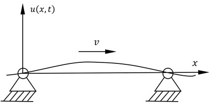
The free wave speed for waves in the stationary belt can be expressed as:
In this formula, P represents the tension of belt and ρ is the linear mass of the belt per unit length which for the experiment is ρ= 9.232×10⁻³ kg/m.
The wave motion in the axially travelling belt is composed of the right travelling wave moving from left to right with the speed of (c+v) and the left travelling wave moving from right to left with the speed of (c-v). Then the periodic time for the travelling wave returning to its original location is given as follows:
The corresponding natural frequency fn and the natural angular frequency ωn of the axially travelling belt are derived from Eq. (5):
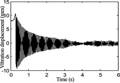
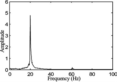
In order to reduce the external interference, such as the vibration from the base, the entire system is located on a vibration isolation space. Three sets of experiments were conducted depending on the adopted tensions values shown in Table 1. The speed of the stepper motor is 30 rpm in the initial configuration and the vibration data of the middle point of the belt were acquired when the stepper motor was steady at a stable speed. The speed of motor was then increased with an increment of 30 rpm for each test configuration until the speed reached 900 rpm. Using the Fast Fourier Transform (FFT) method, the natural frequency value could be obtained for each data set of the transverse free vibration displacement as shown in Fig. 6.
Fig. 6The natural frequency of the belt for a stepper motor speed of 30rpm with the tension of P1= 15 N, a) transverse free vibration displacement with time, b) spectrum of the transverse vibration displacement
a)
b)
It is worth mentioning that the tension of the belt is composed of two parts, the initial pretension force is the main one, the other is the dynamic inertia force caused by the motor speed changes. Therefore, it is needed to adjust the lead screw according to the tension during the experiment as shown in Fig. 2, which satisfies the condition that the tension is approximately the same for the different speeds.
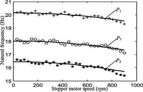
As shown in Fig. 7, the experimental values for the natural frequencies follow the trends of the curves from the theoretical predictions. This is consistent with the theoretical result given in reference [5], where the natural frequency of the transverse vibration decreases with increased rotational speed under different tension conditions; the greater the initial tension, the greater the natural frequency at the same belt speed. Due to the presence of small interference in the experiment, the experimental results are in fair agreement with the theoretical values. At the same time, the results support the validity of the experimental system for linear free vibration.
Fig. 7The curves of the theoretical versus experimental natural frequencies for different belt tensions (P1= 15 N, P2= 12 N and P3= 10 N) and motor speed (30-900 rpm in steps of 30 rpm). The solid black line represents the theoretical value of the natural frequency for each value of corresponding tension, while the scatter indicates the experimental values that were obtained by processing the transverse free vibration displacement from the non-contact laser displacement sensor
4.2. Nonlinear motion phenomena in an axially travelling belt
The relationship between the travelling speed of the belt and the nonlinear vibration was investigated in [7] by a numerical method solving the partial differential dynamic equation of motion. The different response comprising single harmonic, double harmonic, four harmonic and chaotic motion appear successively as the travelling speed of the belt increases. In this paper, the motion equation of the moving belt model according to this experimental device in Fig. 3 can be defined as follows according to the Hamilton principle and the differential constitutive equation defined in Eq. (2):
+2ηA∂u∂x∂2u∂x2∂2u∂x∂t+ηA(∂u∂x)2(∂3u∂x2∂t),
where A is the cross-sectional area of the travelling belt and E0 is Young’s modulus for the material of the belt. In this experiment, A= 8.0×10⁻⁶ m2 and E0=3.14×10⁹Pa.
The speed of the belt is affected by the system during the process of the experiment, so it is necessary to study the influence of the speed fluctuation on the system. The speed of the belt can be expressed as:
in which v0 is the average belt speed; v1 is the speed fluctuation; ω is the frequency fluctuation.
The boundary condition is as follows:
Define the following nondimensional parameters:
Ee=E0AP,Ev=η√AρPL2,γ0=v0√ρAP,γ1=v1√ρAP.
Eq. (8) and the boundary condition can be transformed into the nondimensional form:
=32Ee∂2U∂X2(∂U∂X)2+2Ev∂U∂X∂2U∂X2∂2U∂X∂τ+Ev(∂U∂X)2(∂3U∂X2∂τ),
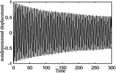
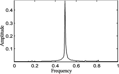
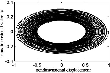
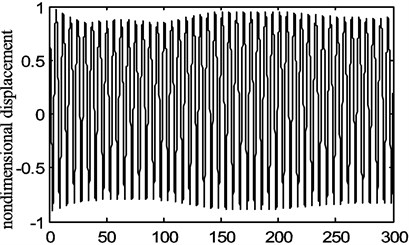
A numerical method was used to study the nonlinear dynamic characteristics of the viscoelastic travelling belt system, the dimensionless parameters selected were: Ee=100, Ev=10, ϖ=1. Several values were given to the parameters γ0 and γ1 respectively.
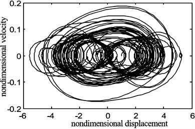
What follows in Fig. 8 to Fig. 10 are numerical simulation results for the theoretical model described above.
Fig. 8The periodic motion of the belt displacement for the fraction of the belt average speed γ0= 0.1, belt speed fluctuation γ1= 0.1
a)
b)
c)
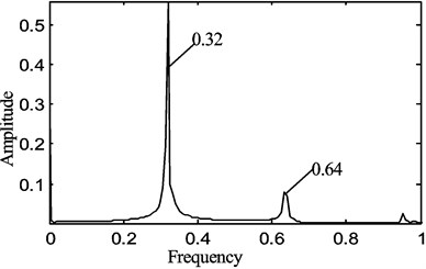
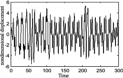
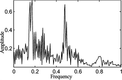
From Figs. 8-10, one can see that the periodic motion, the period doubling motion and the chaotic motion appear in turn as γ0 and γ1 increase. Therefore, the nonlinear motion phenomena of the system is very sensitive to the changes of γ0 and especially the change of γ1, which denote the average moving speed and the speed fluctuation of the system respectively.
Fig. 9The periodic motion of the belt displacement for the fraction of the belt average speed γ0= 0.6, belt speed fluctuation γ1= 0.2
a)
b)
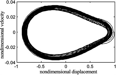
Fig. 10The chaotic motion of the belt displacement for the fraction of the belt average speed γ0= 0.9, belt speed fluctuation γ1= 0.5
a)
b)
c)
In the experimental study of the axially travelling belt under constant speed, it is found that when the rotational speed reaches some fixed values, phenomena such as obvious periodic motion or chaotic motion occurred, which is similar to the behaviour reported in [7] and to the results obtained from the above model.
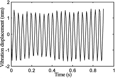
In the tests undertaken, there were corresponding occasions when periodic motion occurred and in some scenarios a beat phenomenon is present in the waveform. When the rotational speed was 120 rpm, there is a clear periodic motion as shown in Fig. 11.
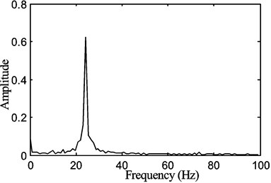
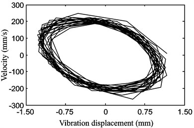
Fig. 11The periodic motion of the belt displacement for a stepper motor speed of 120 rpm with the tension of P1= 15 N
a)
b)
c)
The transverse vibration displacement waveform, the vibration frequency response that was a FFT of the time response waveform and the phase diagram of the displacement versus velocity are shown in Figs. 11(a), (b) and (c) respectively.
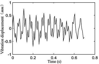
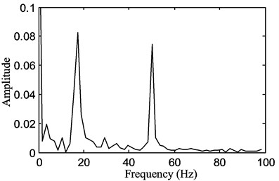
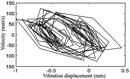
When the rotational speed was increased to 240 rpm, the fundamental frequency in Fig. 12(b) is lower than that one at the speed of 120 rpm in Fig. 11(b). A component of the vibration occurs at a frequency higher than the fundamental in addition to the fundamental frequency as shown in Fig. 12(b). It seems that the change in the travelling speed of the belt has a significant effect on the nonlinear parametric vibration of the belt with the increased travelling speed. The response of the system changes from being a single harmonic vibration to double harmonic vibration. This is present even though the belt is not displacing at amplitudes much dissimilar to the lower belt speed case, so it appears not to be an amplitude dependent effect.
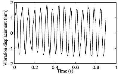
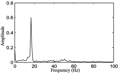
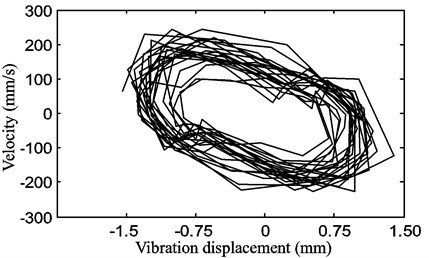
When the rotational speed of the stepper motor reached 300 rpm, the state of the system is changing to a new one where the response is a single harmonic vibration with a fundamental frequency of about 19 Hz in Fig. 13(b), lower than the one at the stepper motor speed of 120 rpm in Fig. 11(b).
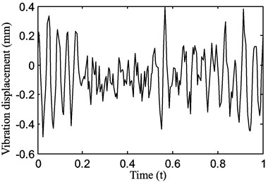
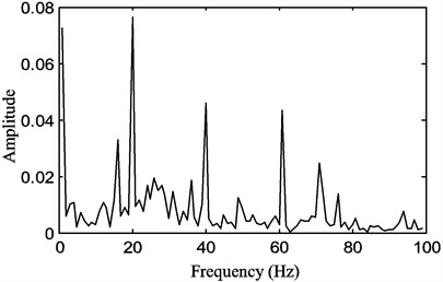
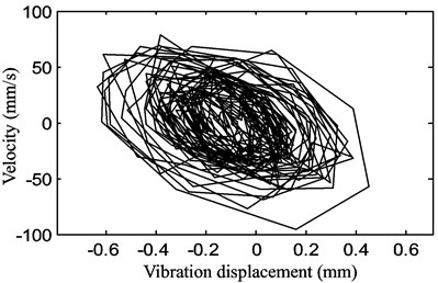
When the rotational speed continued to increase and reached 900 rpm, the state of the system becomes chaotic as shown in Fig. 14.
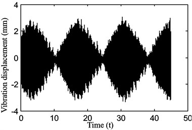
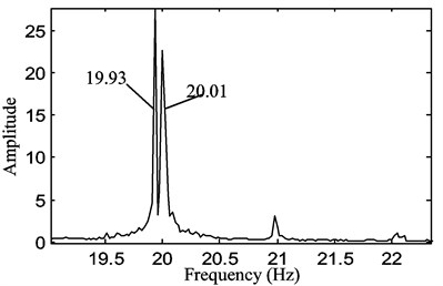
A prominent example of the beat frequency phenomenon is also found in this experiment as shown in Fig. 15.
Fig. 12The motion of the belt displacement for a stepper motor speed of 240 rpm with a belt tension of P1= 15 N, exhibiting vibration at the fundamental frequency and a higher frequency than the fundamental frequency
b)
c)
Fig. 13The periodic motion of the belt displacement for a stepper motor speed of 300 rpm with a belt tension of P1= 15 N
a)
b)
c)
Fig. 14Chaotic motion of the belt for a stepper motor speed of 900 rpm with a belt tension of 15 N
a)
b)
c)
Fig. 15The beating phenomenon in the motion of the belt displacement for a stepper motor speed of 600 rpm with a belt tension of P1= 15 N at two close frequencies of approximately 19.93 and 20.01 Hz
a)
b)
From the correlation theory, when the frequencies of two simple harmonic waves are similar and the amplitude difference is very small, the superposition of the two waveforms produces the “beat”. The waveform amplitude vibrates as a function of time that can be expressed by assuming the transverse deflection is given by the following equation:
The period and frequency of beat can be expressed as follows:
The maximum and the minimum amplitudes of the superimposed waveform can be expressed as follows:
It is obvious that this kind of beat phenomenon is disadvantageous in an axially travelling system requiring high stability, such as in an automotive engine belt drive system, elevator cables and smooth rope-pulley motion systems. So, for practical reasons, it is necessary to avoid the occurrence of beating or prevent it happening. As shown in Eqs. (17-18), the beat amplitude is associated with the two harmonic wave amplitudes, if the difference in the wave amplitudes is large the beat frequency phenomenon will be weak. If the wave amplitudes are similar, the beat frequency phenomenon will be more dominant and likely. So, the system parameters governing the excitation should be adjusted to weaken or lessen the likelihood of the beat frequency phenomenon.
5. Conclusions
In this study, the transverse vibration displacement of an axially travelling belt was successfully measured by a designed experimental platform. The predicted theoretical natural frequencies were in good agreement with those obtained experimentally after frequency analysis of the data and this supports the validity of the travelling wave method. However, the simple travelling wave method is unable to predict the occurrence or likelihood of double periodic or chaotic behaviour appeared in this experiment, which might be caused by the nonlinear relationship between the stress and the strain of the viscoelastic travelling belt. According to the present work, the following conclusions can be drawn:
1) This study achieves an automatic generation of the stepper motor DSP program code by CCS and Matlab software which is highly efficient and accurate.
2) The natural frequency of the axially travelling belt is related to the tension and the motor rotational speed, which agrees with existing theoretical work. Under different tension conditions, the natural frequency is consistent with the change of speed; at fixed speeds, the greater the initial tension the higher the natural frequency.
3) The theoretical simulation and the experimental result correspond qualitatively with one another for some nonlinear phenomena. The stable periodic motion generally occurs for particular speed ranges, but at certain speeds either chaotic motion or motion comprising close oscillating frequencies can occur resulting in beating. The experimental rig now provides a basis for further validation of ongoing theoretical studies into the linear and nonlinear belt dynamics in addition to investigations into methods for the vibration control of the transverse displacement in axially travelling belt systems.
References
-
Li Y. H., Gao Q., Jian K. L., Yin X. G. Dynamic responses of viscoelastic axially moving belt. Applied Mathematics and Mechanics, Vol. 24, Issue 11, 2003, p. 1348-1354.
-
Kim S. K., Lee J. M. Analysis of the nonlinear vibration characteristics of a belt-driven system. Journal of Sound and Vibration, Vol. 223, Issue 5, 1999, p. 723-740.
-
Liu Y. Q., Wang H. Y., Cao D. X., Gai X. L. Dynamic model of the axially moving viscoelastic belt system with tensioner pulley. Proceedings of the International Industrial Informatics and Computer Engineering Conference, Xi’an, Shanxi, China, 2015, p. 354-358.
-
Zhang L., Zu J. W. Nonlinear vibrations of viscoelastic moving belts, part I: free vibration analysis. Journal of Sound and Vibration, Vol. 216, Issue 1, 1998, p. 75-91.
-
Li D. S., Ge X. S. Analyses of an axially moving belt with the natural frequencies and vibrations. Dual Use Technologies and Products, Vol. 2, Issue 2008, 2008, p. 40-42.
-
Zhang W., Wen H. B., Yao M. H. Periodic and chaotic oscillation of a parametrically excited viscoelastic moving belt with 1:3 internal resonance. Chinese Journal of Theoretical and Applied Mechanics, Vol. 36, Issue 4, 2004, p. 443-454.
-
Liu W., Zhang J. F. Analysis of periodic and chaotic oscillations of bifurcation and chaotic motion on transmission visco-elastic belts. Journal of Dynamic and Control, Vol. 3, Issue 3, 2005, p. 63-68.
-
Yao M. H., Zhang W., Zu J. W. Multi-pulse chaotic dynamics in non-planar motion of parametrically excited viscoelastic moving belt. Journal of Sound and Vibration, Vol. 331, Issue 11, 2012, p. 2624-2653.
-
Yao M. H., Zhang W., Zu J. W. Multi-pulse heteroclinic orbits and chaotic motions in a parametrically excited viscoelastic moving belt. International Journal of Bifurcation and Chaos, Vol. 23, Issue 1, 2013, p. 1-28.
-
Zhang W., Gao M. J., Yao M. H. Global analysis and chaotic dynamics of six-dimensional nonlinear system for an axially moving viscoelastic belt. International Journal of Modern Physics B, Vol. 25, Issue 17, 2011, p. 2299-2322.
-
Chen L. H., Zhang W., Yang F. H. Nonlinear dynamics of higher-dimensional system for an axially accelerating viscoelastic beam with in-plane and out-of-plane vibrations. Journal of Sound and Vibration, Vol. 329, Issue 25, 2010, p. 5321-5345.
-
Moon J., Wickert J. A. Nonlinear vibration of power transmission belts. Journal of Sound and Vibration, Vol. 200, Issue 4, 1997, p. 419-431.
-
Tokoro H., Nakamura M., Sugiura N., Tani H., et al. Analysis of transverse vibration in engine timing belt. JASE Review, Vol. 18, Issue 18, 1997, p. 33-38.
-
Pellicano F., Fregolent A., et al. Primary and parametric non-linear resonances of a power transmission belt: experimental and theoretical analysis. Journal of Sound and Vibration, Vol. 244, Issue 4, 2001, p. 669-684.
-
Molteno T. C., Tufillaro N. B. Torus doubling and chaotic string vibrations: experimental results. Journal of Sound and Vibration, Vol. 137, Issue 2, 1990, p. 327-330.
-
Molteno T. C., Tufillaro N. B. An experimental investigation into the dynamics of a string. American Journal of Physics, Vol. 72, Issue 9, 2004, p. 1157-1169.
-
Chen E. W., Lu Y. M., Liu Z. S., et al. Transverse Vibration Measurement System of Axial Moving String and Its Application. China Patent, 201310029837.4, 2014.
-
Zhang N. H. Dynamic analysis of an axially moving viscoelastic string by the Galerkin method using translating string eigenfunctions. Chaos, Solitons and Fractals, Vol. 35, Issue 2, 2008, p. 291-302.
About this article
The authors are greatly indebted to the National Natural Science Foundation of China (Grant No. 51305115, and Grant No. 51675150) for the support of this research.
E. W. Chen contributed to performing the research, setting up the experimental device and designing the experiment contents. H. H. Lin contributed to carrying out the experiment, analyzing the experimental data and writing the manuscript. N. Ferguson contributed to the constructive discussions and feedback. E. W. Chen, H. H. Lin and N. Ferguson reviewed and modified the manuscript.

