Abstract
This paper presents a mathematical model to describe the 2θ in-plane response of supported ring-based MEMS Coriolis Vibrating Gyroscopes (CVGs), including mechanical non-linearity in ring and support structures. Whilst it is well-known that the drive mode resonance frequency of unsupported rings depends on drive amplitude, the proposed model investigates the effects of support geometrical non-linearity on the dynamic behaviour of the 2θ modes. Results indicate that the non-linear stiffness of the supports, combined with the ring non-linearity, breaks the rotational symmetry of the resonator when 8 supports are used, leading to a reduction in sensor gain. In contrast the symmetry of the resonator and performance are maintained when 16 supports are used. The proposed model also demonstrates how the mechanical support non-linearity can be used to guide the design of resonators having a linear drive mode frequency backbone curve.
1. Introduction
Coriolis Vibrating Gyroscopes (CVG’s) are used to measure angular velocity in a wide range of applications, including inertial guidance systems for autonomous aircraft and satellites. Commercial CVG’s are manufactured using MEMS technology and are being developed to achieve navigation grade performance [1, 2]. This paper investigates the effects of mechanical support non-linearity on the dynamic behaviour of resonators used in ring-based CVG’s to enhance performance.
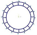
Fig. 1 and Fig. 2 show typical ring resonators used in ring-based MEMS sensors, where the ring is supported either by 8 in-pair or 16 uniformly spaced supports.
Fig. 1Finite element model for ring supported by 8 in-pair supports
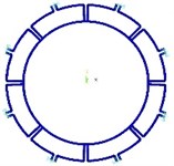
Fig. 2Finite element model for ring supported by 16 supports
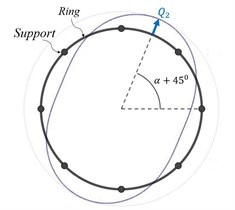
The primary 2θ in-plane flexural vibration mode (drive mode) is excited into resonance by application of external electromagnetic or electrostatic harmonic forces. The Coriolis force arises from the ring rotation about its polar axis, producing a response in the secondary 2θ mode (sense mode) whose amplitude is measured to determine the angular rate experienced by the device [1, 2]. Fig. 3 and Fig. 4 show the drive and sense 2θ modes respectively, which have radial anti-node displacements Q1 and Q2 at angle α and α+45° [3, 4].
To ensure a large mechanical response of the sense mode and improve gain, the drive mode is excited into large amplitude resonant vibration [1, 5]. Under these circumstances, the ring non-linear flexural vibrations cause the drive resonance frequency to depend on the drive amplitude [3]. This complicates the control system and sensor performance as the frequency of the exciting forces needs to be adjusted to maintain drive mode resonance [1, 5].
This paper develops a mathematical model for the ring and supports based on Serandour [6] that includes ring non-linear flexural vibration and the non-linear stiffness of the support structure. The model is used to derive equations governing the drive and sense modes to determine the pseudo-resonance frequency of the drive mode at large vibration amplitude and the amplitude of the sense response under realistic operating conditions. The focus is on perfect rings supported by 8 and 16 supports, which are typically used in state-of-the-art ring-based MEMS gyros to match the drive and sense resonance frequencies in the linear regime. Analytical expressions are determined for the frequency shift of the drive mode resonance frequency as the drive amplitude increases based on the non-linear ring inertia and non-linear support stiffness characteristics. These expressions can be used to guide support design to neutralise the softening trend of ring resonators [3], simplifying the device control system. The sense mode response is also analysed and compared to that of an ideal linear resonator, where ring and support non-linearity is neglected. Results indicate that the number of supports used can break the rotational symmetry of the device when mechanical support non-linearity is included, reducing sensor gain compared to a linear resonator. For rings with 8 supports it is shown that symmetry is broken and performance degrades. However, for rings with 16 supports symmetry is maintained and the resonator behaves the same as an ideal linear resonator.
Fig. 3Drive mode
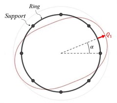
Fig. 4Sense mode
2. Mathematical model
The ring is modelled as an inextensible curved beam with rectangular section. The inertia and stiffness effects of the supports are modelled by discrete mass and non-linear cubic spring elements uniformly attached to the ring and acting in the radial and tangential directions [6]. The inertia and stiffness coefficients for the supports are calculated using a Finite Element model of a single support. The non-linear flexural vibration of the ring is taken into account by including the breathing mode in the radial and tangential ring mid-line displacements [3].
The kinetic and potential strain energies of the ring and support structures are determined and Lagrange’s method used to derive the drive and sense equations of motion in terms of the radial displacements Q1 and Q2, for a ring excited by harmonic radial force (magnitude FD and frequency Ω) and rotating about its polar axis with constant angular velocity Ωz.
2.1. Derivation of the equations of motion
The equations of motion are derived for rings supported by 8 in-pair supports and 16 single supports, as shown in Fig. 1 and Fig. 2 respectively. The sense vibration amplitude is assumed to be much smaller than the drive amplitude, so square and higher powers of Q2 (including derivatives and combinations) and backwards coupling from the drive to the sense response are neglected.
The drive and sense equations of motion for a ring having 8 in-pair supports when the drive force is applied: (i) at the supports (α=0°), and (ii) mid-way between supports (α=22.50) are:
Mring and Mres indicate the linear modal mass of the ring and supported ring resonator, ω0 is the natural frequency of the resonator, and μ is the damping coefficient. The non-linear mass, damping and stiffness terms depend on the drive amplitude vibration via the coefficients γk, I1 and S1. These coefficients relate to the non-linear ring and support mechanical non-linearity: for a linear resonator γk=I1=S1=0. The γk coefficients maintain symmetry between the drive and sense equations. However, I1 and S1 are associated with angle α and are responsible for breaking the rotational symmetry of the resonator, ensuring the drive and sense equations are different for α=0° and α=22.5°.
For a ring having 16 supports, the drive and sense equations of motion are:
The equations of motion obtained for the 16 support structure depend on the drive vibration amplitude, but in contrast to Eq. (1) and Eq. (2) the drive and sense equations are independent of angle α because I1=S1=0, indicating that rotational symmetry is maintained.
3. Non-linear dynamical behavior
The method of averaging is applied to determine an analytical expression for the drive frequency backbone curve and the amplitude of the sense response when the drive mode operates in resonance and the device rotates at angular velocity Ωz.
3.1. Drive response
Applying the method of averaging to Eq. (1) the drive pseudo-resonance frequency ΩD(q1) can be determined for a ring with 8 in-pair supports oscillating at drive amplitude q1. The shift between the drive resonance frequency ΩD(q1) and natural frequency ω0 is given by:
It can be shown easily that the frequency shift for a ring with 16 supports is identical to Eq. (5), but with I1=S1=0. For 8 in-pair supports, Eq. (5) indicates that the pseudo-resonance frequency for a given drive amplitude depends on the location of the exciting force relative to the supports for 8 in-pair supports. However, for 16 supports this dependency is eliminated.
In general, the non-linear frequency shift can be eliminated if the non-linear stiffness and inertia terms in Eq. (5) are zero, or the stiffness and inertia non-linearities balance out. It follows that support geometry can be modified to reduce or eliminate frequency shift at large drive amplitudes.
3.2. Sense response
The sense response can be determined by applying the method of averaging to the sense equation (Eq. (2) for a ring with 8 in-pair supports, and Eq. (4) for 16 supports).
For a ring with 8 in-pairs supports, if the drive mode is driven into resonance and has amplitude q1 it can be shown that the sense amplitude q2 and the phase of the sense response relative to the drive response ϕSD are governed by:
where ΩD(q1) is the harmonic drive.
For the 16 support structure, the sense amplitude q2 and phase ϕSD are:
indicating that the sense response amplitude is linearly proportional to the drive amplitude and angular rate for the 16 support structure. This results is identical to that for a linear vibrating gyroscope [1].
4. Numerical results
Numerical results are obtained for a ring supported by 8 in pair and 16 supports respectively, where the ring radius is ~3 mm, and the axial thickness of ring and supports is ~100 μm. The frequency backbone curves are calculated when the drive force is applied (i) at the supports and (ii) mid-way between supports and compared against the frequency backbone curve for the unsupported ring. Obtained frequency backbone curves are validated against Finite Element (FE) non-linear transient analyses, performed by applying harmonic radial forces to the ring in a push-pull arrangement to excite the 2θ drive mode. The drive mode response is determined by post-processing the radial physical responses and the drive mode pseudo-resonance frequencies are obtained by detecting the frequency inducing a drive response phase of –90° relative to the applied force. Damping is included in the FE model corresponding to a Q-factor value of 1000.
Fig. 5 shows the drive frequency backbone curves obtained for rings having 8 in-pair supports.
The frequency backbone curves obtained for α=0° and α=22.5° are different to each other, confirming the broken rotational symmetry. The frequency shift for the unsupported ring is slightly more softening than the supported ring resonator, indicating that the supports modify the non-linear dynamic behaviour of the drive mode.
Fig. 6 shows the drive mode frequency backbone curves for rings having 16 supports. Obtained curves are unaltered by the location of the force applied relative to the supports, ensuring rotational symmetry is maintained. In this case, the unsupported ring is slightly more softening than the supported ring resonator. Fig. 6 also includes results for the frequency backbone curve obtained for a modified support geometry, where the length of the radial support section attached to the ring is reduced to approx. 50 % compared to Fig. 2. For a drive amplitude of 20 μm the frequency shift is reduced by approx. 75 % compared to the original configuration.
To understand how gyroscope performance is affected by the supports, the sense amplitude (q2) is calculated for increasingly large drive amplitudes when the drive mode is operating at resonance. When there are 8 in-pair supports, the sense amplitude is calculated by solving Eq. (6) and Eq. (7), as q1 is increased. When there are 16 supports, Eq. (8) is used to calculate the sense amplitude. Fig. 7 shows the relationship between the drive and sense amplitudes for three different levels of Q-factor: 10k, 50k and 100k.
Fig. 5Frequency backbone curves for a ring with 8 in-pair supports
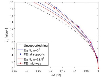
Fig. 6Frequency backbone curves for ring and 16 supports structure
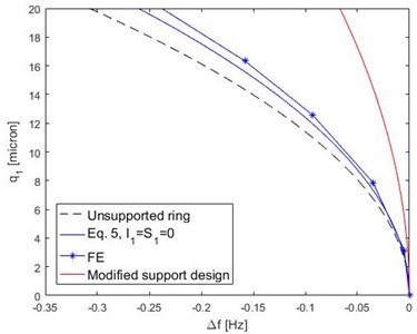
Fig. 7Sense response amplitude in operative condition, parametrical analysis on Q-factor
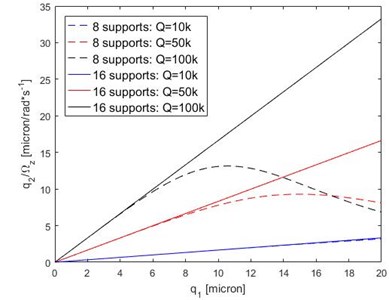
For a ring with 8 in-pair supports, the sense mode amplitude is linearly proportional to the drive amplitude within the linear regime. However, as the drive amplitude increases, the sense amplitude reduces compared to the linear behaviour. The reduction in sense amplitude is more significant and occurs at lower drive amplitudes as the damping reduces (larger Q-factors).
For a ring with 16 supports, the sense amplitude is linearly proportional to the drive amplitude as the drive amplitude increases, and exhibits identical behaviour to that of a linear resonator. The sensitivity of the device can be improved by reducing the damping.
5. Conclusions
A mathematical model was used to determine the non-linear drive and sense responses of ring-based resonators used in CVG’s, where the resonator operates in its 2θ mode pair and has either 8 in-pair supports or 16 uniformly spaced supports. When the ring has 8 in-pair supports it was found that the drive frequency backbone curves depend on the location of the drive axis relative to the supports, breaking the rotational symmetry of the resonator. In contrast the rotational symmetry of the resonator is maintained when the ring has 16 supports. It was found that non-linearity in the supports influences the non-linear dynamic behaviour of the resonator compared to the unsupported ring. A consequence of this is that a support geometry having a hardening behaviour can be used to mitigate the softening behaviour of the ring. This can be used to linearise the drive frequency backbone curve and simplify the control system used in CVG’s to maintain drive mode resonance. Finally, it was shown that the performance of a ring-based CVG’s with an 8 in-pair support degrades as it is driven into large amplitude resonant vibration. This undesirable behaviour can be eliminated by using a ring with 16 supports, and indicates that the non-linear performance of ring based CVG’s is improved by using 16 supports rather than 8.
References
-
Acar C., Shkel A. MEMS Vibratory Gyroscopes: Structural Approaches to Improve Robustness. Springer, Berlin, Germany, 2008.
-
Apostolyuk V. Coriolis Vibratory Gyroscopes: Theory and Design. Springer, Berlin, Germany, 2015.
-
Evensen D. A. Non-linear flexural vibrations of thin circular rings. Journal of Applied Mechanics, Vol. 33, 1966, p. 553-560.
-
Fung Y. C., Sechler E. E. Thin-Shells Structures: Theory, Experiment, and Design. Prentice-Hall, Inc. Englewood Cliffs, New Jersey, 1974.
-
Hu Z., Gallacher B. A mode-matched force-rebalance control for a MEMS vibratory gyroscope. Sensors and Actuators A: Physical, Vol. 273, 2018, p. 1-11.
-
Serandour G., Fox C. H. J., McWilliam S. Modelling geometric nonlinearity in a MEMS resonator. Proceedings of the 9th International Conference on Recent Advances in Structural Dynamics/RASD06, Southampton, 2006.

