Abstract
This work examines a biomechanical system consisting of the hip endoprosthesis and bones of the pelvic region of a person under a load corresponding to the equilibrium of a person in double-supported state. An assessment of the strength of a customised endoprosthesis has been carried out based on the analysis of the stress-strain state of the finite element model of the “skeleton – hip prosthesis” system when tightening the screws and when the system is subjected the person's weight; dangerous areas of the pelvic bone with high level of stresses have been identified. As recommendations, optimization of the location and number of screws used in order to create a more uniform stress distribution is proposed.
1. Introduction
Since the end of the 20th century, a large number of articles about theoretical research of mechanical aspects of interaction between a hip endoprothesis and bone tissue with the use of computer-aided engineering systems based on the finite element method have been published.
In the last decade, there have been publications describing the results of biomechanical studies of the “skeleton-endoprosthesis” system in the conditions of revision arthroplasty associated with significant surgical intervention and individual implant selection. Thus, in works [1, 2] reconstruction of the acetabulum of the pelvis using implants made on the basis of autogenous biological material taken from the fibula is discussed. In articles [3, 4] variants of implant fixation in the pelvic bone are examined from biomechanical positions. In [5], a modular endoprosthesis of a customised shape and size is presented, designed to replace the destroyed half of the pelvis. The paper presents a comparative analysis of the stress distribution between a healthy and restored pelvis in three static positions: sitting, standing on two legs and standing on one leg of the injured side. Loads, regions of their application and kinematic constraints on the degrees of freedom of the model are similar to those described in [6].
The article [7] describes a new approach of creation of implants based on 3D printing technology using the additive layer manufacturing (ALM). This method is ideal for manufacturing of anatomically appropriate individual implants with porous structures layer for bone-implant interface that improve osseointegration [8]. Individual geometry of the acetabulum for each person, corresponding exactly to the damaged areas of the bone, are first designed and then manufactured using a 3D printer.
This article describes the features of numerical modelling of a revision endoprosthesis replacement of the acetabular component of the hip joint. The results of finite element analysis of the stress-strain state system formed by the human skeleton and hip endoprospthesis in double-supported state are presented. Main attention is paid to the calculation of stresses in the pelvic component of the endoprosthesis under static load on the implant, arising from the torque applied during the tightening of the screws into the bone and the person’s weight.
2. Materials and methods
2.1. Finite element models
Modern imaging techniques, such as computer tomography and nuclear magnetic resonance imaging, allow biological structures to be reproduced digitally. The resulting three-dimensional models are used for further analysis by the finite element method.
The complexity of the mathematical description of biomechanical systems leads to the fact that an acceptable analysis of the stress-strain state of the system is impossible without significant preparatory work including processing the geometry of the bone models obtained after the computer tomography. Since the problem is solved by numerical methods of structural mechanics in nonlinear formulation, the models are required to have a high degree of adequacy to real biomechanical processes. This determines the need for the formation of finite element (FE) models with great care: minimizing the imperfections of the mesh, improving the quality of physical and mechanical characteristics of materials, precise assignment of boundary conditions and contact behavior.
The revision hip replacement of a right hip joint is considered in this article. Acetabular region was destroyed with the previous car accident and unsuccessful fracture surgical treatment. Previous primary total hip arthroplasty with simultaneous acetabular posterior column reosteosynthesis was also unsuccessful because of ischium bone full instability. So currently the person receives a voluminous titanium implant with porous structures in the regions of contact with the bone, providing efficient osteointegration over time.
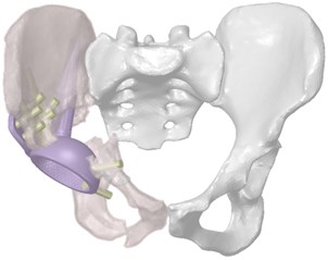
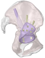
Three-dimensional computer models of the hip system were obtained by computed tomography of the person, on the basis of which the model of individual endoprosthesis was prepared (Fig. 1). Fixation of the customised implant is carried out by means of intrabone stem, a flange on the ilium and screws holding the structure on the ilium bone.
The developed finite element bone models consist of two layers of finite elements with different properties: the outer cortical layer and the inner spongy layer. A complete three-dimensional finite element model of the system is shown in Fig. 2.
Fig. 1Three-dimensional model of the restored hip joint system
2.2. Material characteristics
As the main mathematical model of materials used in finite element models of components of biomechanical construction, the model of linear elastic body according with the generalised Hooke’s law is adopted. The materials were considered as homogeneous with isotropic effective properties. The analysis of scientific publications on the values of physical and mechanical characteristics of materials showed quite a large dispersion, even for standard materials such as titanium and polyethylene. Therefore, average values [9] were taken as the calculated values (Table 1).
Fig. 2Finite element model of the system “skeleton – hip implant”
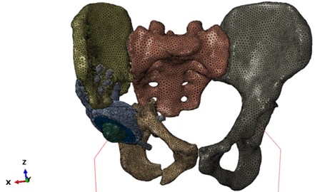
Table 1Physical and mechanical properties of materials
Material | Modulus of elasticity, MPa | Poisson ratio | Density, kg/mm3 | The critical stress, MPa |
Ti6A4V titanium alloy | 110×103 | 0.3 | 4.41×10⁻⁶ | 800 |
Cortical tissue | 10×103 | 0.3 | 1.47×10⁻⁶ | 160 |
Spongy tissue | 0.5×10³ | 0.3 | 0.6×10⁻⁶ | 10 |
Polyethylene (UHMW PE) | 103 | 0.93×10⁻⁶ | 20 |
2.3. Boundary conditions
The statement of the problem of computer modelling in double-supported state is schematically shown in Fig. 3.
In the model under consideration, the loads are applied in two stages. At the first stage, the tightening of screws, that ties the implant and pelvic bones with a torque of 120 N·mm, is simulated. The second stage is a simulation of the human double-supported state by applying a load to the system corresponding to the person's weight of 880 N.
Fig. 3Problem statement
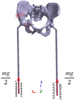
According to human biomechanics, the weight of the person can be represented in the form of a concentrated force at the centre of gravity located in the plane of symmetry of the human body. However, from the equations of the static equilibrium of a solid body, it follows that in a double-supported state, gravity is balanced by the reaction force of the supports, which can be considered equal to half the weight of the person. The results of screws tightening are maintained from the previous step.
Kinematic boundary conditions are imposed in the model: the prohibition of all degrees of freedom of the sacrum, the presence of one degree of freedom in a simplified leg model normal to the lower surface of the prosthesis.
3. Results and discussion
3.1. Modal analysis
As a preliminary calculation, the modal analysis of the assembly as a whole and its separate components is carried out. In this case, it is used to verify the model. The absence of zero oscillation frequencies during the modal analysis ensures the trial of all contact interactions and the absence of unconnected components of the model. The first natural frequency has turned out to be equal to 139.5 Hz. This shows that the prepared finite-element model behaves correctly as a single structure, carrying out free oscillations at given fixations at a natural frequency lying within acceptable numerical limits [10].
3.2. Analysis of stress-strain state of the system
As a result of the calculation, the strength of the components of the biomechanical structure was estimated and a table was compiled to estimate the maximum stresses at different stages of the calculation (Table 2).
Table 2The maximum stresses and factors of safety for model components
Assembly component | Maximum stress, MPa | Factor of safety | ||
Screws tightening | Double-supported state | Screws tightening | Double-supported state | |
The upper part of the pelvic bone (cortical layer) | 31.18 | 147.7 | 5.13 | 1.08 |
The upper part of the pelvic bone (spongy layer) | 2.31 | 10.15 | 4.33 | 0.99 |
The lower part of the pelvic bone (cortical layer) | 36.95 | 88.79 | 4.33 | 1.8 |
The lower part of the pelvic bone (spongy layer) | 3.3 | 4.48 | 3.03 | 2.23 |
Screws | 49.6 | 69.28 | 16.13 | 11.55 |
Implant | 79.6 | 326.5 | 16.13 | 2.45 |
Regarding the distribution of stresses in the components of the system at the step of tightening the screws (Fig. 2), it should be noted that the maximum stresses take place in the group of titanium components of the system, which is correct from the point of view of biomechanics – the person is in a lying position and therefore the pelvic bones do not experience loads. In the implant model, increased stresses take place in the area of screw holes and in the area of contact interaction with the bone.
The main concentration of stresses in the bones of the destroyed (right) half of the pelvis takes place in the cortical layer around the holes for titanium screws caused by the tension of titanium screws, tightening the implant with other parts of the pelvis. However, the calculation shows that, in local areas near the edges of the screw holes, the stresses do not exceed the Allowed limits for the cortical and spongy bones; in addition, as they go further from the edges of the stresses, they quickly decrease to less than 1 MPa. The upper part of the pelvic bone of the right half of the pelvis is integrally loaded: there is contact with the implant, end-to-end location of the implant stem and seven screw connections, two of which are embedded in the spongy layer, and therefore this part is the most vulnerable.
According to the mechanical statement of the problem, the second stage involves loading the structure with a force equivalent to the weight of the person's body. The value of the stresses in the screw system increased as expected since the group of titanium components of the system at the second stage takes the weight of the person, but there is a sufficient factor of safety. In the model of the implant, increased stresses at this stage also take place in the area of the screw holes, but the highest stresses level occur in the area of contact interaction of the implant stem with the bone edge, since there is a direct support of the legs and the implant.
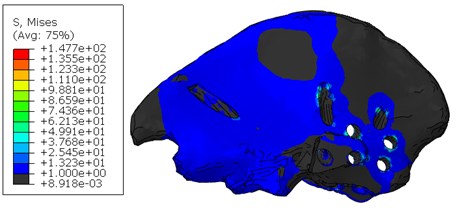
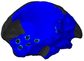
Stresses in the upper part of the pelvic bone of the right half of the pelvis increase several times compared to the previous stage (Fig. 5). Stress concentration is observed on the edges of screw holes and on the edge of the hole for the implant stem. In this area, local problems are expected, since maximum stresses on the edge exceed the permissible ones.
Fig. 4Stresses in the cortical layer of the upper part of the pelvic bone after tightening the screws
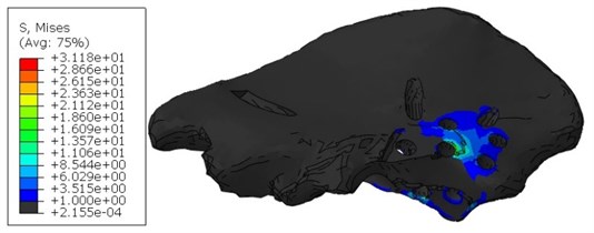
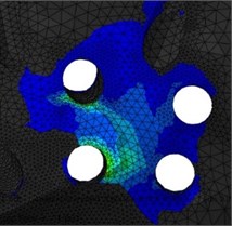
Fig. 5Stresses in the cortical layer of the upper part of the pelvic bone when standing
4. Conclusions
The article examines the important problem of biomechanics of the restored hip joint with the use of an custom implant. Several recommendations can be given to improve the strength. It is necessary to avoid overloading of the cortical layer of the hip bone when installing the implant. The area of the cortical layer in contact with the flange of the prosthesis is subjected to two mechanical effects: the tightening force from the screws and the pressure from the flange and the implant cup. Therefore, it is recommended in order to achieve the fullest possible coincidence of the geometric surfaces to avoid additional stresses from the geometric mismatch of the contacting surfaces. It is also recommended to find the optimal spatial location of the screws, since the tight positioning of the screws leads to the formation of thin walls in the bone tissue, which can adversely affect the integrity of the system. At the same time, the combination of stress concentrators, which take place in some regions of the upper part of the pelvic bone, leads to a significant increase in the stress level, which is undesirable for maintaining the strength and fatigue life of the system.
It has been found that, at the second stage of the calculation, the most dangerous area is the area of the upper part of the right pelvic bone in the area of the implant stem exit to the bone surface. Effective osteointegration of the porous part of the implant and the person's bone without serious loads in the first weeks after surgery is proposed as recommendations for reducing the stress-strain state.
References
-
Sakuraba M., Kimata Y., Iida H., Beppu Y., Chuman H., Kawai A. Pelvic ring reconstruction with the double-barreled vascularized fibular free flap. Plastic and Reconstructive Surgery, Vol. 116, 2005, p. 1340-1345.
-
Yu G., Zhang F., Zhou J., Chang S., Cheng L., Jia Y. Microsurgical fibular flap for pelvic ring reconstruction after periacetabular tumor resect ion. Journal of Reconstructive Microsurgery, Vol. 23, 2007, p. 137-142.
-
Guo W., Tang S., Dong S., Li X. Resection and reconstruction for tumors of iliac bone. Chinese Journal of Surgery, Vol. 44, 2006, p. 813-816.
-
Yamamoto Y., Takeda N., Sugihara T. Pelvic ring reconstruction with a vascularized bone flap of femur. Plastic and Reconstructive Surgery, Vol. 100, 1997, p. 415-417.
-
Zhou Y., Min L., Liu Y., Shi R., Zhang W., Zhang H., Duan H., Tu C. Finite element analysis of the pelvis after modular hemipelvice endoprosthesis reconstruction. International Orthopaedics, Vol. 37, 2013, p. 653-658.
-
Jia Y.-W., Cheng L.-M., Yu G.-R., Du C.-F., Yang Z.-Y., Yu Y., Ding Z.-Q. A finite element analysis of the pelvic reconstruction using fibular transplantation fixed with four different rod-screw systems after type I resection. Chinese Medical Journal, Vol. 121, 2008, p. 321-326.
-
Wong K. C., Kumta S. M., Geel N. V., Demol J. One-step reconstruction with a 3D-printed, biomechanically evaluated custom implant after complex pelvic tumor resection. Computer Aided Surgery, Vol. 20, Issue 1, 2015, p. 14-23.
-
Colen S., Harake R., De Haan J., Mulier M. A modified custom-made triflanged acetabular reconstruction ring (MCTARR) for revision hip arthroplasty with severe acetabular defects. Acta Orthopaedica Belgica, Vol. 79, 2013, p. 71-75.
-
Borovkov A., Maslov L., Zhmaylo M., Zelinskiy I., Voinov I., Keresten I., Mamchits D., Tikhilov R., Kovalenko A., Bilyk S., Denisov A. Finite element stress analysis of a total hip replacement in a two-legged standing. Russian Journal of Biomechanics, Vol. 4, 2018, p. 382-400.
-
Levadnyy E.V., Nushtayev D.V.Issledovaniye Napryazhenno Deformirovannogo Sostoyaniya Verkhney treti bedrennoy kosti pri eye mezhvertelnom perelome i nakostnoy fiksatsii s primeneniyem sheyechnogo vinta so spiralevidnoy rezboy. Tr. Mezhdunar. Foruma, 2014, (in Russian).

