Abstract
Solenoids are commonly used in numerous industrial applications, where they convert electrical energy into mechanical motion. The present paper is focused on implementing a solenoid-type actuator in vibration-driven locomotion systems. The primary purpose of this study is simulation and experimental testing of the dynamic behavior of a wheeled vibratory robot taking into account the operational conditions of a solenoid-type vibration exciter. The research methodology involves the use of the SolidWorks software to simulate the robot’s locomotion, TinkerCAD software – to model the operation of a solenoid’s control system, and experimental investigations – to test the kinematic characteristics of the full-scale prototype of the vibration-driven robot. The results obtained by means of computer simulation and experimental studies are presented as time plots, displaying the robot’s body displacement, speed, and acceleration at different operational conditions of the solenoid-type actuator. The major scientific novelty of the present study consists in further development and improvement of the existent excitation principles and simulation models of the vibration-driven locomotion systems and wheeled robots. The obtained results are valuable for researchers and engineers working on investigating and designing of various vibratory locomotion systems, e.g., for pipeline inspection and cleaning.
Highlights
- The study simulated and experimentally tested the dynamics of a wheeled vibratory robot actuated by a controllable solenoid-type exciter.
- A 3D design was created in SolidWorks, a control system model was developed in TinkerCAD, and a full-scale laboratory prototype was built for experimental validation.
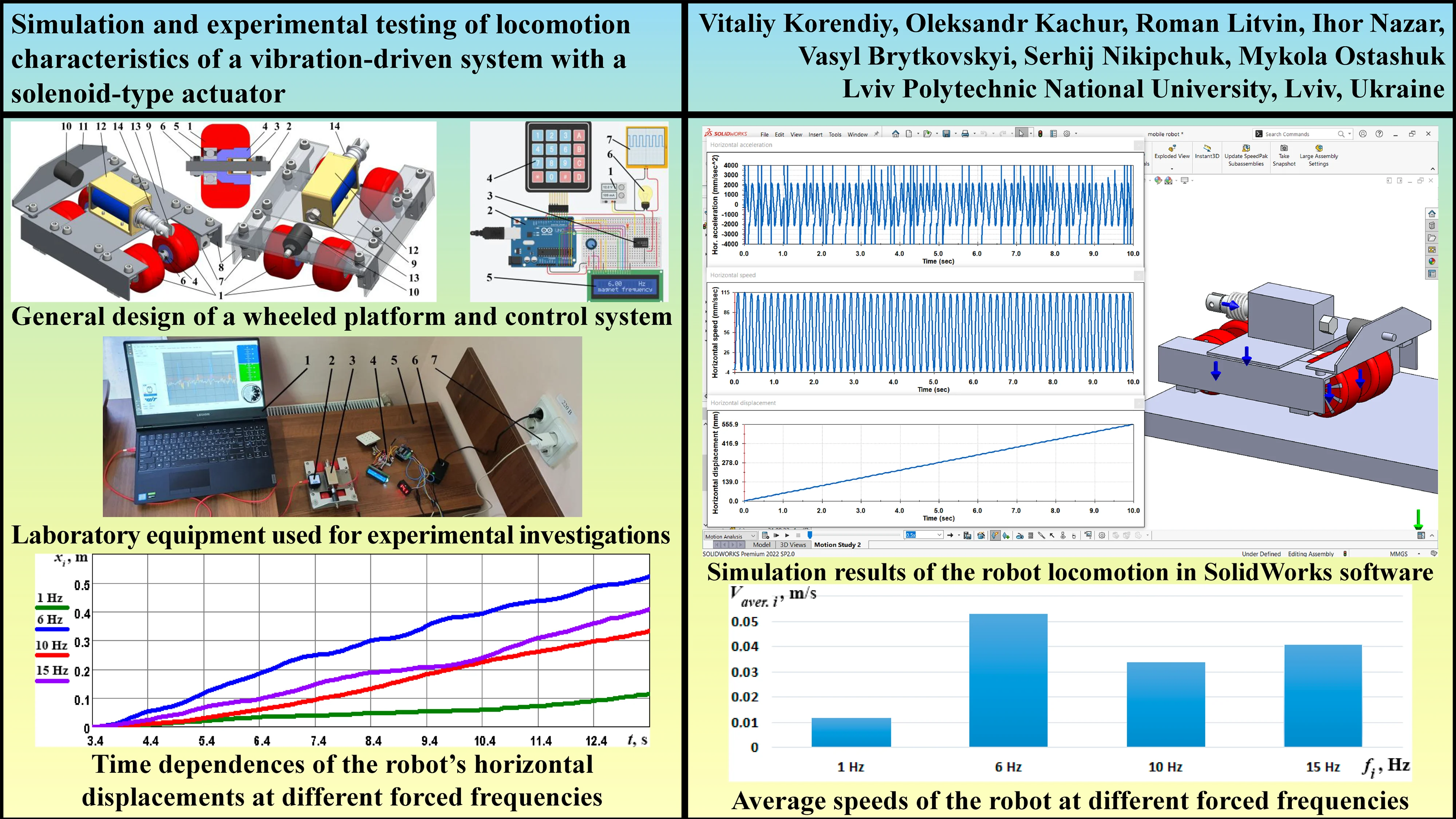
- Experiments measured the robot's acceleration, speed, and displacement at forced frequencies of 1, 6, 10, and 15 Hz under a supply voltage of 3 to 12.5 V.
- The experiments achieved maximum frame accelerations up to 4 m/s^2 (at 15 Hz) and the robot traveled maximal distances up to 0.53 m in 10 seconds (at 6 Hz).
- The highest average locomotion speed, approximately 0.053 m/s, was observed at the 6 Hz frequency, which is attributed to stable vibro-impact working regimes occurring at this specific frequency.
1. Introduction
Vibration-driven locomotion systems and vibratory robots utilize mechanical vibrations as their primary mode of movement [1]. These systems operate by converting vibrational energy into directional motion, often through asymmetric frictional forces between the robot and the surface it moves on [2]. Vibratory robots are typically simple in design, lightweight, and capable of navigating a variety of environments [3]. This type of locomotion is particularly useful in small-scale robots, such as micro-robots and swarm robots, where conventional wheel or leg-based mechanisms are inefficient or impractical [4]. The primary advantages of vibration-driven systems include their simplicity, robustness, and ability to traverse irregular or challenging terrains [5]. They are often energy-efficient and can be designed with few moving parts, reducing mechanical wear [6]. However, controlling the direction and speed of vibratory robots can be complex due to their reliance on surface interactions and environmental factors [7], [8]. Recent advancements in materials science, control algorithms, and sensor integration have expanded the potential applications of vibratory robots, from medical devices that navigate within the human body to autonomous systems exploring confined or hazardous spaces. The ongoing development of these technologies promises to improve their precision, functionality, and adaptability in diverse fields.
Solenoid-type actuators are electromechanical devices that convert electrical energy into linear mechanical motion through electromagnetic principles [9]. A typical solenoid actuator consists of a coil of wire, which generates a magnetic field when current is passed through it, and a movable iron core, or plunger, which is pulled into the coil’s center when the magnetic field is activated [10]. This linear movement can be used to perform mechanical tasks such as opening valves, triggering switches, or operating locks [11], [12]. These actuators are valued for their simplicity, reliability, and rapid response times. They are widely used in various applications, including automotive systems, industrial machinery, and consumer electronics, where precise on-off control or positioning is required. Solenoids are often preferred due to their compact size and ability to produce significant force from a small form factor [13]. However, solenoid-type actuators can be limited by their relatively short stroke length and the tendency to generate heat during prolonged operation, which can reduce efficiency [14]. Their performance is also dependent on the current supplied, and higher power requirements are necessary for larger-scale operations [15]. Recent advancements in materials and design have improved the efficiency and durability of solenoid actuators, expanding their use in more energy-conscious and performance-critical applications.
The present paper continues the authors’ previous investigations [16], [17] and is aimed at modeling the dynamic behavior of a vibration-driven locomotion system taking into account the technical characteristics and operational conditions of the solenoid-type vibration exciter [18]. In all previous studies, e.g., [1], [7], [8], [16], [17], similar vibration-driven locomotion systems were equipped with slider-crank mechanisms or imbalanced rotors for vibration excitation, and the inertial forces they generated could only be adjusted by changing the excitation frequency.
The improved design of the vibration-driven robot studied in the present paper focuses on the controllable solenoid-type vibration exciter, which can vary the actuating inertial force by adjusting the supplied voltage with the help of the specially designed control system. Moreover, the developed control system also allows for adjustments in the excitation frequency.
The simulation and experimental studies conducted in the present paper are critically important for further practical implementation of vibration-driven robots with solenoid-type exciters, which have been previously designed by the authors for inspecting (monitoring) and cleaning the internal surfaces of pipelines and are currently in the manufacturing stage (see Fig. 1).
Fig. 1Vibration-driven in-pipe robots designed by the authors and equipped with solenoid-type exciters
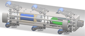
a) Inspecting robot
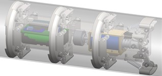
b) Cleaning robot
2. Research methodology
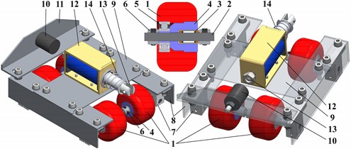
The first stage of the present investigation deals with developing a 3D design of a wheeled vibration-driven robot actuated by a solenoid-type exciter using the SolidWorks software (see Fig. 2). To perform locomotion, the robot uses the wheels 1 installed on the axles 2 with the help of the ball bearings 5 and overrunning clutches 3 mounted in the bushings 4. The sliding of the wheels 1 along the axles 2 is constrained by the clamps 6. The other set of clamps 7 is used to fix the front and rear axles 2 to the robot’s frame girders 8 on which there is mounted the plate 9 with the solenoid 12. The front frame member 11 is fixed on the girders 8 and holds the rubber bumper 10. The plunger (armature) 13 performs the reciprocating (back-and-forth) movements relative to the robot’s frame due to supplying the sinusoidal current to the solenoid coil and installing the additional return spring 14. The front end of the plunger 13 periodically impacts the bumper 10 setting into motion the whole robot. The latter moves in a forward direction while its backward motion is restricted by the overrunning clutches allowing single-way rotation of the wheels.
Fig. 2General design of a wheeled platform actuated by a solenoid-type vibration exciter
Based on the developed 3D design of the wheeled vibration-driven robot, the corresponding full-scale laboratory prototype (Fig. 3(a)) and control system (Fig. 3(b)) are developed and experimentally tested at the Vibroengineering Laboratory of Lviv Polytechnic National University. The voltage supplied to the driver 3 is manually controlled by the regulator 1 within the range of 0,…, 24 V registered by the voltmeter 8. The Arduino microcontroller 2 and keypad 4 are used for adjusting the necessary frequency of the signal sent to the driver 3, which powers the solenoid 6 coil by a rectangular alternating voltage with a minimum value of 0 V and maximal one set by the regulator 1. The user-defined forced frequency is shown on the LCD display 5. The control system model developed in the TinkerCAD software contains the lamp 6 simulating the solenoid (Fig. 3(b)). The voltage signals supplied to the lamp 6 are registered by the oscilloscope 7. To study the robot’s locomotion conditions, the accelerometer 7 is fixed on its frame (Fig. 3(a)).
The experimental technique involves processing the accelerometer 2 data in the WitMotion software installed on the laptop 1 (see Fig. 4). The solenoid 3 is powered by the control and power supply system 4. Due to the plunger reciprocating movements, the robot’s wheels roll over the supporting surface 5. The control system is powered by the voltage adapter 7, and the amplitude of the plunger is controlled by the voltage supplied by the regulator 6. The experiments are carried out at the forced frequencies of 1, 6, 10, and 15 Hz, and supplied voltage of 12,…, 12.5 V.
Fig. 3Full-scale laboratory prototype of the robot with the solenoid-type actuator and control system
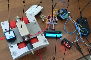
a) Experimental prototype of the wheeled robot
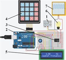
b) Simulation model of the control system
3. Results and discussion
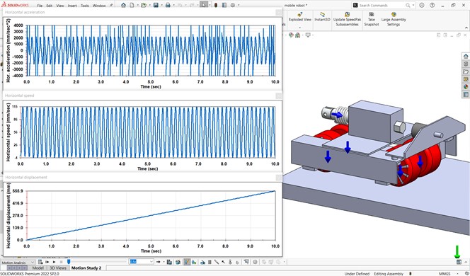
Before conducting full-scale experimental investigations of the mobile vibration-driven robot, the simulation of its locomotion was performed in the SolidWorks software at the excitation frequency of 6 Hz. The corresponding results are presented in Fig. 5. At the steady-state locomotion conditions, the amplitude of the robot’s horizontal acceleration is approximately 2000 mm/s², while its velocity varies between –4 and 115 mm/s. Over a time period of 10 seconds, the robot covered a distance of about 556 mm, which means that its average locomotion speed is 5.56 mm/s. These results are similar to the authors’ previous findings shown in [16].
Fig. 4Laboratory equipment used for experimental investigations
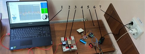
Fig. 5Results of simulation of the robot’s locomotion carried out in the SolidWorks software
The experimental investigations were performed at the forced frequencies of 1, 6, 10, and 15 Hz. The corresponding data obtained from the accelerometer and processed in the WitMotion software are shown in Fig. 6. The maximal values of the robot’s frame horizontal accelerations reach approximately 0.5, 2, 3, and 4 m/s2, respectively. The corresponding decelerations take on almost the same values with a minus sign, but their time repeatability is lower.
Fig. 6Experimentally obtained accelerations of the robot’s frame at different forced frequencies
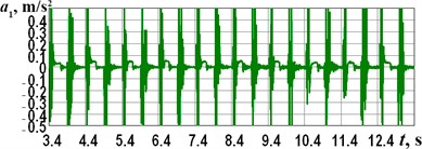
a) 1 Hz
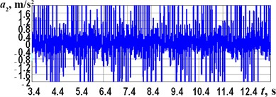
b) 6 Hz
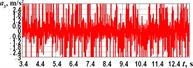
c) 10 Hz
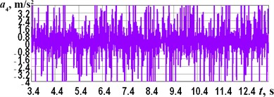
d) 15 Hz
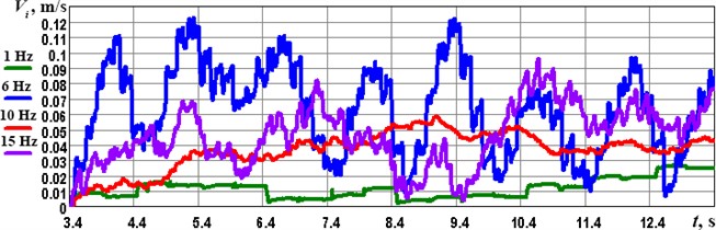
Performing numerical approximation and integration of the obtained time dependencies of the robot’s horizontal accelerations in the Wolfram Mathematica software, the corresponding plots describing the robot’s speed changes in time are presented in Fig. 7. The maximal peaks of the speed reaching the values of 0.12 m/s are observed at the forced frequency of 6 Hz, while the minimal speed, which takes place at the forced frequency of 1 Hz, does not exceed 0.03 m/s. Considering the frequencies of 1 and 10 Hz, the robot moves at more stable locomotion regimes, while the frequencies of 6 and 15 Hz cause wider drops in the locomotion speeds. These phenomena may be explained by the robot’s operation in the near-resonance regimes generating mechanical beats. Therefore, further investigations on this subject may be focused on substantiating the excitation conditions of the solenoid-type actuator that eliminate the occurrence of the unstable locomotion regimes, as well as optimizing the amplitude and forced frequency to minimize the consumed power and maximize the locomotion speed of the robot.
Fig. 7Time dependences of the robot’s speeds at different forced frequencies
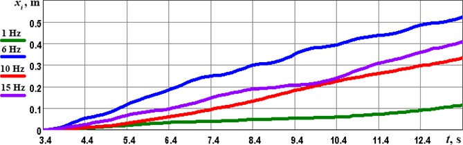
One more stage of numerical integration of the experimental data allows for obtaining the time dependencies of the robot’s horizontal displacement. As shown in Fig. 8, during the time period of 10 s, the robot’s frame passes distances of approximately 0.11 m, 0.33 m, 0.41 m, and 0.53 m at the forced frequencies of 1 Hz, 10 Hz, 15, and 6 Hz. Therefore, the largest average locomotion velocity of the considered wheeled vibration-driven robot is observed at the forced frequency of 6 Hz. This may be explained by the fact that the mentioned forced frequency provides the stable vibro-impact working regimes of the solenoid-type vibration exciter, when each back-and-forth movement of the solenoid’s plunger (armature) is accompanied by its impact on the rubber bumper. Considering the cases of 10 and 15 Hz forced frequencies, the solenoid does not have enough power to provide these impacts at each period of the plunger oscillations, and the vibro-impact regimes are not stable. Similar conclusions have been drawn in the authors’ previous papers [1], [2], [7], [16] considering other types of vibration exciters. Therefore, the prospects of further investigations may be focused on substantiating the optimal excitation conditions and impact gap values for ensuring the best locomotion performance and minimal power consumption.
Fig. 8Time dependences of the robot’s horizontal displacements at different forced frequencies
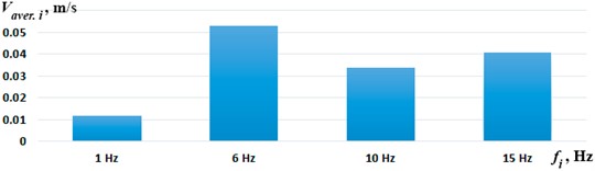
Summarizing the obtained experimental results, Fig. 9 shows the average locomotion speeds of the considered wheeled vibration-driven robot at different forced frequencies. As already mentioned, the largest speed of approximately 0.053 m/s is observed at the forced frequency of 6 Hz, while the minimal one does not exceed 0.011 m/s at 1 Hz. In general, the experimental results (Figs. 6-8) are in good agreement with the computer simulation results shown in Fig. 5.
Fig. 9Average speeds of the wheeled vibration-driven robot at different forced frequencies
4. Conclusions
The paper considers the wheeled vibration-driven robot with a solenoid-type exciter developed at the Vibroengineering Laboratory of Lviv Polytechnic National University. The 3D design of the robot is created in the SolidWorks software, and its locomotion conditions are simulated at the 6 Hz forced frequency of the solenoid plunger oscillations. The special control system is developed to adjust the excitation conditions of the robot’s full-scale laboratory prototype. The experiments are carried out at the forced frequencies of 1, 6, 10, and 15 Hz, and supplied voltage of 12,…, 12.5 V. The maximal values of the robot’s frame horizontal accelerations reach the values of approximately 0.5, 2, 3, and 4 m/s2, respectively. During the time period of 10 s, the robot’s frame passes distances of approximately 0.11 m, 0.33 m, 0.41 m, and 0.53 m at the corresponding forced frequencies. The robot’s largest speed of approximately 0.053 m/s is observed at the forced frequency of 6 Hz, while the minimal one does not exceed 0.011 m/s at 1 Hz.
The obtained findings are valuable for researchers and engineers working on the studying and designing of various vibration-driven locomotion systems, such as those used for pipeline inspection and cleaning. The prospects of further investigations may be focused on substantiating the optimal excitation conditions and impact gap values for ensuring the best locomotion performance (maximal locomotion speed) and minimal power consumption.
References
-
V. Korendiy et al., “Motion simulation and impact gap verification of a wheeled vibration-driven robot for pipelines inspection,” Vibroengineering Procedia, Vol. 41, pp. 1–6, Apr. 2022, https://doi.org/10.21595/vp.2022.22521
-
V. Korendiy, V. Gursky, O. Kachur, V. Gurey, O. Havrylchenko, and O. Kotsiumbas, “Mathematical modeling of forced oscillations of semidefinite vibro-impact system sliding along rough horizontal surface,” Vibroengineering Procedia, Vol. 39, pp. 164–169, Dec. 2021, https://doi.org/10.21595/vp.2021.22298
-
V.-D. Nguyen and N.-T. La, “An improvement of vibration-driven locomotion module for capsule robots,” Mechanics Based Design of Structures and Machines, Vol. 50, No. 5, pp. 1658–1672, May 2022, https://doi.org/10.1080/15397734.2020.1760880
-
J. Tian, K. O. Afebu, Z. Wang, Y. Liu, and S. Prasad, “Dynamic analysis of a soft capsule robot self-propelling in the small intestine via finite element method,” Nonlinear Dynamics, Vol. 111, No. 11, pp. 9777–9798, Apr. 2023, https://doi.org/10.1007/s11071-023-08376-z
-
H. Fang and K. W. Wang, “Piezoelectric vibration-driven locomotion systems – exploiting resonance and bistable dynamics,” Journal of Sound and Vibration, Vol. 391, pp. 153–169, Mar. 2017, https://doi.org/10.1016/j.jsv.2016.12.009
-
J. Chavez, V. Böhm, T. I. Becker, S. Gast, I. Zeidis, and K. Zimmermann, “Actuators based on a controlled particle-matrix interaction in magnetic hybrid materials for applications in locomotion and manipulation systems,” Physical Sciences Reviews, Vol. 7, No. 11, pp. 1263–1290, Nov. 2022, https://doi.org/10.1515/psr-2019-0087
-
V. Korendiy, V. Gursky, O. Kachur, P. Dmyterko, O. Kotsiumbas, and O. Havrylchenko, “Mathematical model and motion analysis of a wheeled vibro-impact locomotion system,” Vibroengineering Procedia, Vol. 41, pp. 77–83, Apr. 2022, https://doi.org/10.21595/vp.2022.22422
-
V. Korendiy and O. Kachur, “Locomotion characteristics of a wheeled vibration-driven robot with an enhanced pantograph-type suspension,” Frontiers in Robotics and AI, Vol. 10, p. 12391, Aug. 2023, https://doi.org/10.3389/frobt.2023.1239137
-
H.-S. Lee, S.-G. Park, M.-P. Hong, H.-J. Lee, and Y.-S. Kim, “A study on the manufacture of permanent magnet traction control valve for electronic stability control in electric vehicles,” Applied Sciences, Vol. 11, No. 17, p. 7794, Aug. 2021, https://doi.org/10.3390/app11177794
-
A. M. Hosseini, S. Arzanpour, F. Golnaraghi, and A. M. Parameswaran, “Solenoid actuator design and modeling with application in engine vibration isolators,” Journal of Vibration and Control, Vol. 19, No. 7, pp. 1015–1023, Mar. 2012, https://doi.org/10.1177/1077546311435517
-
L. Yang, T. Gao, X. Du, F. Zhai, C. Lu, and X. Kong, “Electromagnetic characteristics analysis and structure optimization of high-speed fuel solenoid valves,” Machines, Vol. 10, No. 10, p. 964, Oct. 2022, https://doi.org/10.3390/machines10100964
-
A. Demarchi, L. Farçoni, A. Pinto, R. Lang, R. Romero, and I. Silva, “Modelling a solenoid’s valve movement,” Lecture Notes in Computer Science, Vol. 11175, pp. 290–301, Sep. 2018, https://doi.org/10.1007/978-3-030-00308-1_24
-
M. N. El-Derini, “Mathematical model of a solenoid for energy and force calculations,” Journal of Physics D: Applied Physics, Vol. 17, No. 3, pp. 503–508, Mar. 1984, https://doi.org/10.1088/0022-3727/17/3/008
-
Z. Peng, L. Chen, L. Wei, W. Gao, Q. Yu, and C. Ai, “Analysis and identification of a dynamic model for proportional solenoid,” IEEE Access, Vol. 9, pp. 92651–92660, Jan. 2021, https://doi.org/10.1109/access.2021.3092142
-
M. F. Badr, “Modelling and simulation of a controlled solenoid,” in IOP Conference Series: Materials Science and Engineering, Vol. 433, No. 1, p. 012082, Nov. 2018, https://doi.org/10.1088/1757-899x/433/1/012082
-
V. Korendiy, O. Kachur, V. Gurskyi, and P. Krot, “Studying the influence of the impact gap value on the average translational speed of the wheeled vibration-driven robot,” Engineering Proceedings, Vol. 24, No. 1, p. 25, Sep. 2022, https://doi.org/10.3390/iecma2022-12897
-
V. Korendiy, P. Krot, O. Kachur, and V. Gurskyi, “Analyzing the locomotion conditions of a wheeled vibration-driven system with a V-shaped suspension,” in Lecture Notes in Mechanical Engineering, Cham: Springer Nature Switzerland, 2024, pp. 153–163, https://doi.org/10.1007/978-3-031-63720-9_14
-
V. Korendiy, O. Kachur, and V. Zakharov, “Development of a control system for a vibratory lapping-polishing machine,” in 2023 IEEE XXVIII International Seminar/Workshop on Direct and Inverse Problems of Electromagnetic and Acoustic Wave Theory (DIPED), Vol. 24, pp. 233–237, Sep. 2023, https://doi.org/10.1109/diped59408.2023.10269520
About this article

The authors have not disclosed any funding.
The datasets generated during and/or analyzed during the current study are available from the corresponding author on reasonable request.
The authors declare that they have no conflict of interest.
