Abstract
A methodology for the design calculation of a new design of a hydraulic pulse vibrator with a valve pressure pulse generator of a parametric type has been developed, which allows determining its energy, power and geometric parameters.
1. Introduction
One of the ways to develop vibration technology is to minimize the size without deteriorating the technical characteristics [1]. Analysis of the results of studies on the development of vibrators with different types of drives [1-8] has established that vibrators based on a hydraulic pulse drive using elastic elements of high stiffness [1, 9] have the smallest dimensions with significant oscillating power parameters. There is no generally accepted methodology for calculating the design of hydro-pulse vibrators, so it is necessary to carry out research to substantiate the methodology for calculating the corresponding new design of the vibrator in order to obtain the best technical and economic indicators.
2. Researches methodology
The methodology for calculating the design of a small-sized hydraulic pulse vibrator will be considered for the device whose structural and design scheme is shown in Fig. 1 [1, 10]. A feature of the design is the compactness of the structure due to the use of elastic elements of high rigidity and the construction of the structure based on a hydraulic pulse drive.
Fig. 1Design scheme of a small-sized hydraulic pulse vibrator with a built-in valve pressure pulse generator
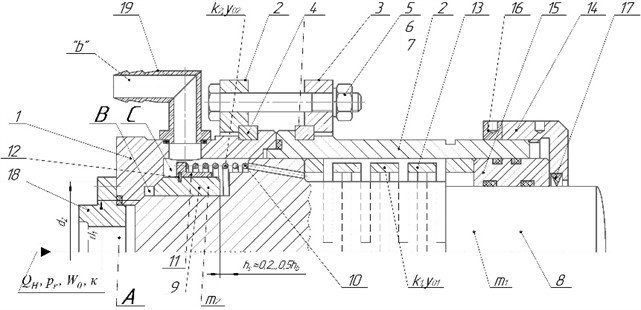
Hydraulic pulse vibrator with valve sealing stages of the pressure pulse generator (PPG), containing energy supply and discharge lines, cover 18, pressure pulse generator body 1, which is connected to the sleeve 2 by means of half rings 4, flanges 2 and 3, which are tightened through half rings 4 with bolts 5 and nuts 6, secured with spring washers 7. Plunger 8 on the valve part of which there is a valve sleeve 9, which is supported against the chamfer of the body 1 by a split spring ring 12, a stepped sleeve 11, coiled 10 and slotted springs13, a guide sleeve 15 and a cap nut 14, which is secured with a lock nut 16 and in which a dirt collector 17 is installed.
The maximum frequency of the pressure pulses is determined by the power supply of the hydraulic pump of the hydraulic pumping station supplying the vibrator hydraulic system. The theoretical value of the flow rate can be found by the following formula [11]:
where – theoretical cycle coefficient of pressure pulses; – the initial volume of the pressure cavity of the hydraulic system of the vibrator; – maximum “opening” pressure PPG; – modulus of elasticity; – volumetric efficiency of the hydraulic pump (for a hydraulic pump of the gear pump [9, 10]). Since the cyclogram of the vibrator operating cycle is indicative (conditional), the has an estimating nature, which necessitates the introduction of a margin factor in Eq. (1) , the value of which can be refined based on the results of experimental studies based on the recommendations of [10], we accept 1.1,..., 1.25, then the calculated value:
We will find the estimated value from the approximate cyclogram of the working cycle, using the concept of the scale of the pressure pulse sec/mm (Fig. 2).
By measuring the segments on the indicative cyclogram of the vibrator’s duty cycle , , and (see Fig. 2), define:
Taking into account Eq. (3) in the formula for calculate:
Fig. 2On the concept of pressure pulse scale
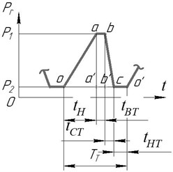
According to the approximate cyclogram we have proposed: = (100⋅32)-1= 0.0003125 sec/mm, then, according to Eq. (4), 1.88. Taking into account this value in Eq. (2) and and 0.95,..., 0.96, find:
where the average value is taken 0.955
To calculate the required cross-sectional area of a fully open PPG vibrator , it is necessary to know the average energy flow rate through this gap during the time of reduction of the energy carrier pressure in the hydraulic system of the vibrator from level to level (reduction of the deformation of the hydraulic link from to ). By analogy with the known dependence [12], the time can be estimated by the formula:
Whence, under the assumption of linearity of the function [12] define:
where – is the relative time of energy carrier pressure reduction in the pressure cavity of the vibrator (see Fig. 1) from level to level . Since, according to the approximate cyclogram of the vibrator’s operating cycle , then 1 and . During theoretical studies of the mathematical model of the vibrator, it is advisable to coordinate the value with the calculated value .
To avoid such negative phenomena as cavitation during the operation of the PPG vibrator, it is necessary to limit the speed of the energy carrier through the gap to the permissible one :
The energy carrier flow also passes through the open gap of the locking element of the first level of PPG sealing with a speed of:
where – negative opening of the closing element (plunger 8) of the first sealing level, as can be assigned =, but provided that , for , for example, by assuming the flow rate of the energy carrier through the gap such as safety valves [12], or , then we can assume that =. When developing the mathematical model of the vibrator, we assumed that and . The validity of the above assumptions should be verified during theoretical studies of the mathematical model of the vibrator and experimental studies of its prototype. As a certain margin of safety, let’s take and , from Eqs. (8) and (9) for and , find:
3. Results and discussion
According to the assumption structure adopted by us, as in [9, 13, 14], in the guides of the plunger 8 and the valve sleeve 9 (see Fig. 1) there is only a liquid friction mode, then, accordingly, the energy balance of the forward stroke of the locking elements of the first and second sealing stages of the PPG vibrator is determined by equation:
where – average work of energy carrier pressure forces during the direct stroke of the mass (plunger 8 and valve sleeve 9, see Fig. 1); – increase in potential deformation energy of the slot spring 13; – increase in the potential strain energy of the coiled spring 10 (see Fig. 1); – increase in potential deformation energy of the elastic part of the hydraulic link; – the total average work of friction forces during the straight stroke movement of the plunger 8 and the valve sleeve 9:
According to the reasonable structure of assumptions adopted by us, the friction mode in the guides of the plunger 8 and the valve sleeve 9 is fluid, and , which allows us to neglect the components and in the energy balance Eq. (11) and write this equation in the form of inequality:
or taking into account Eqs. (12), (13) and (15):
where from:
or:
where ; , – see Eq. (13) and (23); sign takes into account the neglect of components and in the Eq. (11).
The average diameter of the first level of sealing of the PPG vibrator is found from the Eq. (10):
The throughput of the vibrator PPG according to Eq. (8) depends on the energy carrier flow rate and is determined by the diameter and negative overlap :
or taking into account Eq. (7):
The relative time for reducing the pressure of the energy carrier in the pressure cavity of the vibrator can be estimated based on the results of the analysis of experimental studies of the hydraulic pulse drive of vibrating and vibration-impact machines (oscillograms of changes in the pressure of the energy carrier in the pressure cavities of the hydraulic pulse drive [13-14]. According to this analysis, the average value is 2.3,..., 2.8 for the average frequency range of pressure pulses (20...100) Hz and amplitude of (9,..., 10) MPa. In accordance with the comments made, we will have:
where = 1.1,…, 1.2 – reserve factor, which takes into account the indicative nature of the calculation and . Taking into account the value of , find:
The cross-sectional area of the fitting screwed into the threaded hole of the cover 18 (Fig. 1) and the cross-sectional area of the opening of the high-pressure hose connecting the pressure cavity of the vibrator to the hydraulic pumping station supplying the vibrator with energy carrier must be sufficient to allow the flow of energy carrier at a rate of (or , as we have accepted that ):
where – the diameter of the hole in the high-pressure hose, which can be considered the conditional passage of the vibrator. From Eq. (25) for , we obtain:
Through the open slot of the first stage of sealing of the PPG of the vibrator passes the flow of energy with a permissible speed , it is obvious that at this speed this flow of energy must pass through the cross-sectional area , then from the equation of equality of speeds of the flow of energy:
find:
where previously (see the text to (23)) .
Substituting Eq. (28) into (10), we have:
Taking into account Eq. (29) in (23), we finally find:
Taking , to turn the inequality into an equality, we determine the required stiffness of the slotted springs 13, taking into account Eq. (28) (see Fig. 1):
In order for the coiled spring 10 (see Fig. 1) to work “in time” with the dynamic oscillatory process of the vibrator, its mode of operation must be resonant, which is determined by the condition [13]:
whence .
The initial force of the spring 10 is determined by the deformation during the assembly of the vibrator, and the working force is determined by the fact that during most of the forward and reverse strokes of the plunger 8 and the valve sleeve 9 they move as one (). Other geometrical dimensions of the vibrator are determined during the development of the vibrator design according to the generally accepted rules for the design of hydraulic and, in particular, hydraulic pulse machines, mechanisms and devices.
The method has been tested for a vibrator with a nominal “opening” pressure of PPG – 10 MPa, an amplitude of oscillations – 0.5,..., 2,0 mm and a frequency of passage of pressure pulses – 10,..., 100 Hz.
4. Conclusions
1) The developed method of design calculation of a hydraulic pulse vibrator with a valve PPG allows determining all the main energy, power and geometric parameters of the vibrator using relatively simple formulas.
2) According to the results of theoretical studies of the mathematical model of the vibrator after checking the adequacy of this model, correlating (clarifying) coefficients can be introduced into the calculation dependencies and formulas of the developed methodology for the design calculation of the vibrator in order to increase their correctness and accuracy.
3) The principles and approaches used in the developed design calculation methodology for determining the vibrator parameters can be the basic basis for constructing design calculation methods for other hydroimpulse vibrators and devices.
References
-
R. Obertyuh, A. Slabkyі, O. Polishchuk, and O. Hanpantsurova, “Hydropulse small-sized vibrators based on slotted springs,” Journal of Mechanical Engineering and Transport, Vol. 15, No. 1, pp. 124–130, Jul. 2022, https://doi.org/10.31649/2413-4503-2022-15-1-124-130
-
S. Qiaolei, X. Le, L. Yuwei, and D. Long, “Structure design on a new type of coupled impactor,” Journal of Physics: Conference Series, Vol. 2707, p. 012155, Feb. 2024, https://doi.org/10.1088/1742-6596/2707/1/012155
-
H. Lingxia, S. Qiaolei, D. Long, L. Yuwei, and F. Ding, “Structural design and effect analysis on a new type of hydraulic oscillator driven with double valve groups,” Scientific Reports, Vol. 12, p. 15719, Sep. 2022, https://doi.org/10.1038/s41598-022-20116-8
-
A. A. Cherno, “Control of electromagnetic vibratory drive using a phase difference between current harmonics,” Journal of Automation and Information Sciences, Vol. 49, No. 7, pp. 58–76, Jan. 2017, https://doi.org/10.1615/jautomatinfscien.v49.i7.50
-
P. Tang, H. Zhao, B. Zhu, J. Lu, and W. Zhang, “Study on the Influence of geometric parameters on vibration characteristics of hydraulic oscillator used in oil drilling,” Journal of Physics: Conference Series, Vol. 2752, p. 012213, Jun. 2024, https://doi.org/10.1088/1742-6596/2752/1/012213
-
X. Y. Wang, Y. T. Ma, G. Y. Yan, and Z. H. Feng, “A compact and high flow-rate piezoelectric micropump with a folded vibrator,” Smart Materials and Structures, Vol. 23, No. 11, p. 115005, Nov. 2014, https://doi.org/10.1088/0964-1726/23/11/115005
-
K. R. Massarsch, “Monitoring and process control of deep vertical vibratory compaction using resonance amplification,” ISSMGE International Journal of Geoengineering Case Histories, Vol. 8, No. 1, pp. 22–38, Jan. 2024, https://doi.org/10.4417/ijgch-08-01-02
-
O. Kachur, V. Korendiy, O. Lanets, R. Kachmar, I. Nazar, and V. Heletiy, “Dynamics of a vibratory screening conveyor equipped with a controllable centrifugal exciter,” Vibroengineering Procedia, Vol. 48, pp. 8–14, Feb. 2023, https://doi.org/10.21595/vp.2023.23175
-
R. Obertyukh, A. Slabkyі, L. Polishchuk, O. Povstianoi, S. Kumargazhanova, and M. Satymbekov, “Dynamic and mathematical models of the hydroimpulsive vibro-cutting device with a pressure pulse generator bult into the ring spring,” Informatyka, Automatyka, Pomiary w Gospodarce i Ochronie Środowiska, Vol. 12, No. 3, pp. 54–58, Sep. 2022, https://doi.org/10.35784/iapgos.3049
-
R. Obertyukh, A. Slabkyі, A. Priymachenko, and V. Ishchenko, “Hydropulse vibrator with valve sealing stages of the pressure pulse generator,” UA Patent 149943, 2021.
-
R. Obertyukh, “Method of design calculation of a hydropulse device for strain hardening of materials,” Przegląd Elektrotechniczny, Vol. 2019, No. 4, pp. 67–75, Apr. 2019, https://doi.org/10.15199/48.2019.04.12
-
R. Obertykh, A. Slabkyі, S. Аndrukhov, and V. Kudrash, “Parametric single-time generators impulses of a pressure increased towing confidence,” Journal of Mechanical Engineering and Transport, Vol. 9, No. 1, pp. 82–88, Jul. 2019, https://doi.org/10.31649/2413-4503-2019-9-1-82-88
-
R. Obertyukh and A. Slabkyі, Devices for Vibroturning on the Basis of a Hydraulic Pulse Drive. Vinnytsia: VNTU, 2015.
-
R. Iskovych-Lototskyi, R. Obertyukh, and O. Polishchuk, Use of a Hydraulic Pulse Drive in the Equipment of Processing Industries. Vinnytsia: VNTU, 2013.
About this article

The authors have not disclosed any funding.
The datasets generated during and/or analyzed during the current study are available from the corresponding author on reasonable request.
The authors declare that they have no conflict of interest.
