Abstract
The paper aims to analyze the improved design of an in-pipe vibration-driven robot, which is equipped with a self-locking mechanism, electromagnetic exciter, and size-adapting devices. The study focuses on examining the robot’s locomotion conditions at different working regimes. The research methodology contains four main stages: analysis of the design peculiarities of the enhanced wheeled in-pipe vibration-driven robot; developing a simplified dynamic diagram and deriving the differential equations to describe its locomotion conditions; carrying out numerical modeling with the help of Mathematica software to analyze the robot’s basic dynamic parameters; conducting virtual experiments and testing the robot locomotion characteristics by means of the computer simulation in SolidWorks Motion software. The results obtained include the time-based data on the robot’s displacement, speed, acceleration, and consumed power under different operating conditions, such as varying forced frequencies and excitation force amplitudes. The novelty of this investigation lies in identifying efficient working regimes for the improved wheeled vibration-driven robot intended for moving inside the pipelines. Future research will focus on developing a full-scale experimental prototype of the robot and conducting laboratory investigations at different working regimes. The findings of this research are valuable for scientists and engineers involved in the study and design of similar vibration-driven locomotion systems.
Highlights
- The improved design of an in-pipe vibration-driven robot, which is equipped with a self-locking mechanism, electromagnetic exciter, and size-adapting devices, is analyzed and its locomotion conditions are studied at different working regimes.
- The simplified dynamic diagram of the robot’s oscillatory system is developed and the differential equations describing its locomotion conditions are derived. Numerical modeling is carried out with the help of Mathematica software to analyze the robot’s basic dynamic parameters.
- Virtual experiments on the robot’s locomotion characteristics is conducted by means of the computer simulation in SolidWorks Motion software. The results obtained present time-based data on the robot’s displacement, speed, acceleration, and consumed power under different operating conditions.
1. Introduction
The maintenance, monitoring, inspection, and cleaning of the inner surfaces of pipelines, tubes, vessels, and similar structures are frequently managed with the help of in-pipe or pipeline robots [1]. These robots come in various designs, with the most prevalent being those utilizing wheeled, tracked (caterpillar), screw-drive, inchworm, and snake-like locomotion systems [2]. PIG-type (pipe inspection gauge) robots, along with other bio-inspired designs, are commonly employed for performing tasks within pipes [3]. To enable these robots to adjust to the changing geometrical parameters of the pipes they navigate, a range of passive and active reconfigurable mechanisms are used [4]. One of the most commonly utilized in-pipe robots features a wheeled chassis [5]. Different designs of these robots, which are equipped with active adapting mechanisms, have been developed and extensively investigated in [6], [7]. The authors of [8] introduced the initial concept of a four-wheel robot actuated by an inertial vibration exciter. Subsequent studies [9], [10] focused on mathematical modeling, simulation, and experimental studies of the vibratory robots at different working regimes. Novel prototypes of walking and crawling mechanisms of mobile in-pipe robots have also been explored in [11], [12]. Additionally, in [13], the potential for employing various image-processing techniques has been discussed to inspect the internal surfaces of tubes and pipelines using wheeled robots driven by DC motors.
Enhanced mechatronic systems designed for semi-automatic pipeline monitoring and cleaning operations are discussed in [14]. Similar studies focused on a novel inchworm robot actuated with the help of a cam-linkage mechanism are presented in [15]. Comprehensive analysis of autonomous robots designed for inspecting defects in underground pipelines is carried out in [16], [17]. The control of locomotion characteristics in subsea pipeline robots is examined in [18]. The challenges of a robot navigating through the girth weld of a gas pipeline are thoroughly considered in [19]. In [20], the authors explore the locomotion conditions of a pipeline robot equipped with a fluid-structure coupling. The results of an extensive study on the optimal sliding models of an electromagnetically driven worm-like robot are reported in [21]. An enhanced design and control strategies for a V-shaped pipeline robot are discussed in [22]. The operational characteristics of the wheeled wall-pressing robots are examined in [23, 24]. The dynamic behavior of the pipeline robot with omnidirectionally rotating wheels driven by permanent electromagnets is analyzed in [25]. Additionally, in [26], there is analyzed an innovative design of a wheeled vibration-driven in-pipe robot, which uses an enhanced non-circular gear mechanism in its drive.
The initial concept for this paper was introduced in the authors' previous works [27]-[29]. Particularly, in [27], a simplified design diagram of the wheeled vibration-driven pipeline robot was created, and mathematical modeling along with computer simulations of the robot locomotion was conducted. The paper [28] is focused on the experimental estimation of the robot’s locomotion parameters at different working regimes. In [29], there was considered the initial design of the vibration-driven robot able to move inside circular tubes and pipelines. The current paper aims to develop an improved design of the autonomous wheeled vibration-driven robot, which features the self-locking and self-adapting mechanisms set into motion by a solenoid-type actuator. The robot is designed to move inside pipelines of various cross-sections and to conduct photo and video inspections of the conditions of their internal surface (welds, couplings, joints, cracks, etc.).
2. Research methodology
The robot is composed of a frame (body) 1 that holds all the other components (Fig. 1).
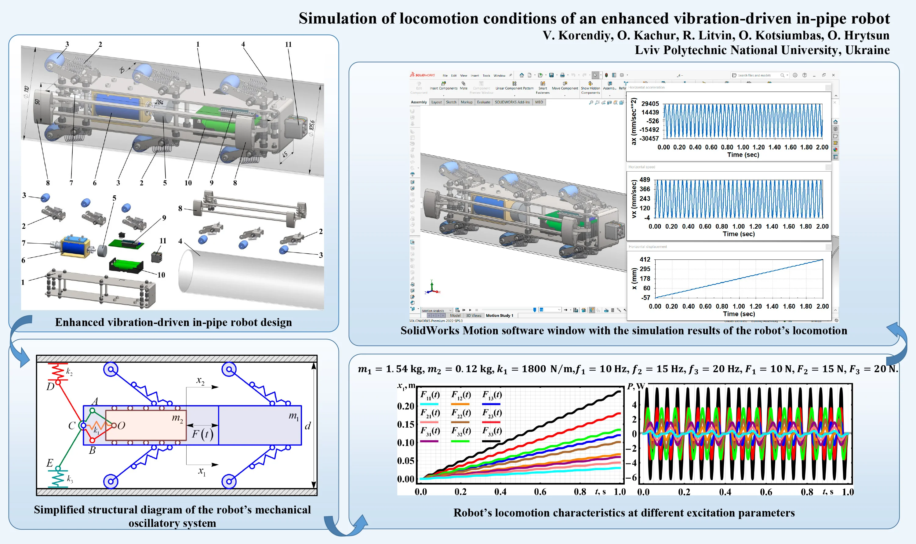
Fig. 1Enhanced vibration-driven in-pipe robot design
The lever-type spring-restrained linkages 2, equipped with rollers 3, support the robot’s frame 1 inside the pipeline 4. Vibrations of the disturbing (internal) body 5 are induced by the solenoid-type exciter 6. The rear end of the pusher (tappet, plunger, armature) 7 is hingedly joined to a linkage-type braking system 8, which provides self-locking regimes and unidirectional locomotion for the vibration-driven robot inside a pipeline. The control system 9 utilizes Arduino software and hardware, powered by rechargeable batteries 10. To perform photo and video inspections of the conditions of the pipeline’s internal surfaces, the camera 11 is installed at the front end of the robot’s frame. Consequently, the robotic platform slides inside the pipeline 4 in a single direction due to the periodic disturbances caused by the oscillating (reciprocating) motion of the internal body 5. The self-locking linkage-type braking system 8, driven by the solenoid tappet 7, prevents the robot from moving backward.
Unlike the previous design of the similar robot considered in [29] and mostly used for cleaning the internal surfaces of the pipelines, the current design (Fig. 1) is intended only for monitoring the internal conditions (weldments, couplings, joints, cracks, etc.). The major difference between these designs is the motion principle: previous robot used the sliding regimes where the scrappers slide along the internal surface, while the current robot employes the rolling regimes where the rollers move inside the pipeline. In the last case, the friction losses and energy consumption are much smaller, and the robot may be more effectively used for monitoring the in-pipe conditions.
The simplified structural diagram of the robot’s oscillatory system is depicted in Fig. 2. In the considered mechanical system, the body of the mass represents the robot’s frame, and the body of the mass corresponds to the internal (disturbing) body. The lever-type spring-restrained linkages, equipped with rollers, support the robot’s frame inside the pipeline (tube). The oscillations (reciprocating motion) of the internal body are excited due to the action of the periodic force , which can be approximately considered as sinusoidal or cosinusoidal one and is applied between the robot’s frame and the disturbing body. The braking (self-locking) system comprises two linkages OACE and OBCD, which form a twin lever-type mechanism with spring elements characterized by the stiffness coefficients , , and . The periodic disturbing force induces reciprocating inertial forces, which act upon the internal mass and are transmitted to the robot’s body. Such design of the robot’s mechanical system enables it to move in a stepwise unidirectional manner inside the pipeline of the changeable diameter . The translational motion of the robot’s body is represented by the generalized coordinate , while the position of the internal body is described by the coordinate .
Fig. 2Simplified structural diagram of the robot’s mechanical oscillatory system
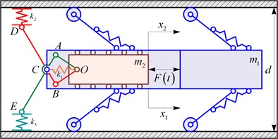
Assuming the braking (self-locking) mechanism operates perfectly, we can disregard it while deducing the mathematical model (system of differential equations) for the robot’s locomotion. Under this assumption, the vibration-driven robot is able to move freely forward, while its backward motion is completely restricted. We will consider as the reduced stiffness of the entire braking (self-locking) mechanism acting on the internal (disturbing) body . Consequently, the following differential equations can be deduced to model the robot’s translational locomotion:
where the braking (self-locking) force can be modeled by the simplified formula:
and the excitation force is described by the periodical (sinusoidal) function:
where is the amplitude value of the excitation force; is the angular frequency of forced oscillations; – is the forced frequency of the solenoidal excitation.
The function determines the direction of the robot locomotion: forward if the robot speed is positive, and backward if the speed is negative. When the robot moves in the forward direction, the braking (self-locking) force is considered to be zero. Conversely, when the robot attempts to move backward, the braking (blocking) force is generated, equating to the sum of all active forces exerted on the robot’s wheeled chassis.
Neglecting the power losses due to the damping and friction, and taking into account the ideal steady-state working regimes of the vibration exciter (operating at the constant forced frequency and unchanged amplitude value of the excitation force ), the approximate expression for determining the time dependence of the consumed power can be derived as follows:
3. Results and discussion
Let us employ the fifth-order Runge-Kutta methods integrated into Wolfram Mathematica software to solve the system of differential equations (1) and (2) that describes the robot’s locomotion behavior. The initial conditions are set to zero: . The basic design parameters of the vibration-driven robot are taken from its 3D model developed in the Dassault SolidWorks software (see Fig. 1): the robot’s body (frame) mass is 1.54 kg, the internal (disturbing) body mass is 0.12 kg, and the reduced stiffness of the self-locking mechanism’s spring system is assumed to be approximately equal to 1800 N/m. The mentioned parameters allow for rough estimating the natural angular frequency of the robot’s mechanical oscillatory system:
where is the reduced mass of the robot’s mechanical oscillatory system.
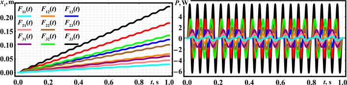
For performing further numerical modeling, let us consider the following forced frequencies and amplitude values of the periodical (sinusoidal) excitation forces: 10 Hz ( 62.83 s–1), 15 Hz ( 94.25 s–1), and 20 Hz ( 125.66 s–1), 10 N, 15 N, and 20 N. These values of the forced frequency allow for studying the far-before resonance and near-resonance working regimes of the robot’s mechanical oscillatory system. The corresponding results of numerical modeling performed in the Wolfram Mathematica software are shown in Fig. 3. The results are illustrated in the form of time dependencies of the robot’s frame displacement and consumed power under steady-state operational conditions.
The robot’s locomotion is characterized by a periodic abrupt (stepwise) regime along a straight horizontal path. The wheeled vibration-driven robot travels distances of approximately 0.031 m, 0.046 m, 0.061 m, 0.068 m, 0.101 m, 0.135 m, 0.121 m, 0.182 m, and 0.242 m in 1 second under the action of the corresponding excitation forces , , , , , , , , . This results in average translational speeds of about 0.031 m/s, 0.046 m/s, 0.061 m/s, 0.068 m/s, 0.101 m/s, 0.135 m/s, 0.121 m/s, 0.182 m/s, and 0.242 m/s. The peak (amplitude) value of the consumed power of about 6 W is achieved at the forced frequency of 20 Hz and the excitation force of the 20 N amplitude value.
Fig. 3Robot’s locomotion characteristics at different excitation parameters
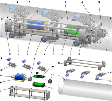
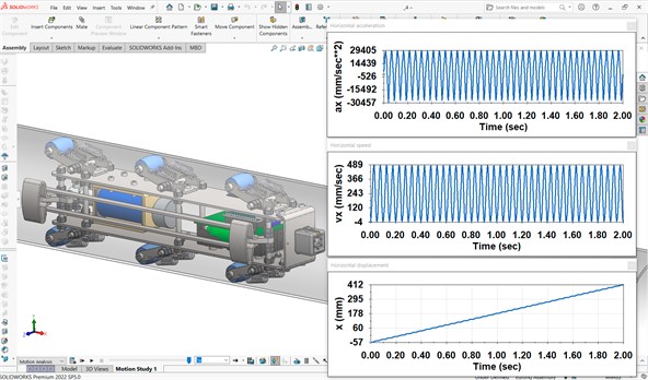
Computer simulation of the locomotion conditions of the wheeled vibration-driven in-pipe robot was conducted using SolidWorks Motion software at the excitation force amplitude 20 N and disturbing frequency 20 Hz. The simulation window with the obtained results is shown in Fig. 4. Over a simulation period of 2 s, the robot’s position changed from –57 mm to 412 mm, indicating that it traveled approximately 469 mm. This results in the robot’s average translational speed of around 235 mm/s. Due to the slippage processes in the braking (self-blocking) mechanism, the robot periodically moved backward at a maximum speed of approximately 3…4 mm/s, while the amplitude value of its forward speed does not exceed 489 mm/s. The lowest and highest acceleration values were –30457 mm/s² and 29405 mm/s². In general, the modeled character of the robot’s locomotion, as well as its basic kinematic characteristics, correspond to the other similar investigations presented in [27]-[29].
Fig. 4SolidWorks motion software window with the simulation results of the robot’s locomotion
4. Conclusions
This paper explores an advanced wheeled vibration-driven locomotion system that features a solenoid-type (electromagnetic) exciter along with a spring-rod self-locking (blocking, braking) mechanism. This innovative robot is specifically designed for the purpose of conducting photo and video inspections of the internal surfaces of various pipelines and tubes. The study delves into the dynamics of the robot’s movement through mathematical modeling using Wolfram Mathematica software and computer simulations conducted with Dassault SolidWorks software.
The research finds that the robot achieves its maximum average locomotion speed, which ranges between 0.235 to 0.245 m/s, when operating at a forced frequency of 20 Hz and an excitation force amplitude of 20 N. The chosen disturbance frequency is substantiated to provide the efficient near-resonance operation of the robot’s mechanical oscillatory system. These findings suggest practical applications in the design of new in-pipe robot prototypes, enhancing their control systems, and optimizing their operational parameters.
Future research could focus on the development and experimental testing of a prototype based on this design, which would validate the theoretical and simulation results. This next step would involve creating a tangible model to test the performance and efficiency of the proposed vibration-driven locomotion system in real-world pipeline inspection scenarios. The insights gained from this research could significantly contribute to advancing the field of in-pipe robotics, improving inspection accuracy, and ensuring the reliability of pipeline infrastructure.
References
-
H. Jang et al., “A review: technological trends and development direction of pipeline robot systems,” Journal of Intelligent and Robotic Systems, Vol. 105, No. 3, p. 59, Jul. 2022, https://doi.org/10.1007/s10846-022-01669-2
-
A. Verma, A. Kaiwart, N. D. Dubey, F. Naseer, and S. Pradhan, “A review on various types of in-pipe inspection robot,” Materials Today: Proceedings, Vol. 50, pp. 1425–1434, Jan. 2022, https://doi.org/10.1016/j.matpr.2021.08.335
-
B. John and M. Shafeek, “Pipe inspection robots: a review,” in IOP Conference Series: Materials Science and Engineering, Vol. 1272, No. 1, p. 012016, Dec. 2022, https://doi.org/10.1088/1757-899x/1272/1/012016
-
C. Rusu and M. O. Tatar, “Adapting mechanisms for in-pipe inspection robots: a review,” Applied Sciences, Vol. 12, No. 12, p. 6191, Jun. 2022, https://doi.org/10.3390/app12126191
-
R. S. Elankavi, D. Dinakaran, R. M. K. Chetty, M. M. Ramya, and D. G. H. Samuel, “A review on wheeled type in-pipe inspection robot,” International Journal of Mechanical Engineering and Robotics Research, Vol. 11, No. 10, pp. 745–754, Jan. 2022, https://doi.org/10.18178/ijmerr.11.10.745-754
-
A. Kaiwart, N. D. Dubey, F. Naseer, A. Verma, and S. Pradhan, “Design of adaptive wheel driven pipeline inspection robot,” in Lecture Notes in Mechanical Engineering, Singapore: Springer Singapore, 2022, pp. 583–595, https://doi.org/10.1007/978-981-16-9613-8_54
-
E. Cao, H. Tan, Y. Bian, Z. Guo, and F. Zhou, “Design and realization of a 6-wheeled in-pipe robot,” in Journal of Physics: Conference Series, Vol. 2356, No. 1, p. 012010, Oct. 2022, https://doi.org/10.1088/1742-6596/2356/1/012010
-
V. Korendiy, O. Kachur, V. Gurskyi, and P. Krot, “Studying the influence of the impact gap value on the average translational speed of the wheeled vibration-driven robot,” Engineering Proceedings, Vol. 24, No. 1, p. 25, Sep. 2022, https://doi.org/10.3390/iecma2022-12897
-
V. Korendiy and O. Kachur, “Locomotion characteristics of a wheeled vibration-driven robot with an enhanced pantograph-type suspension,” Frontiers in Robotics and AI, Vol. 10, p. 12391, Aug. 2023, https://doi.org/10.3389/frobt.2023.1239137
-
V. Korendiy, P. Krot, O. Kachur, and V. Gurskyi, “Analyzing the locomotion conditions of a wheeled vibration-driven system with a V-shaped suspension,” in Lecture Notes in Mechanical Engineering, Cham: Springer Nature Switzerland, 2024, pp. 153–163, https://doi.org/10.1007/978-3-031-63720-9_14
-
S. Kazeminasab and M. K. Banks, “SmartCrawler: a size-adaptable in-pipe wireless robotic system with two-phase motion control algorithm in water distribution systems,” Sensors, Vol. 22, No. 24, p. 9666, Dec. 2022, https://doi.org/10.3390/s22249666
-
G. H. Jackson-Mills et al., “Non-assembly walking mechanism for robotic in-pipe inspection,” Lecture Notes in Networks and Systems, Vol. 324, pp. 117–128, Sep. 2021, https://doi.org/10.1007/978-3-030-86294-7_11
-
A. Colvalkar, S. S. Pawar, and B. K. Patle, “In-pipe inspection robotic system for defect detection and identification using image processing,” Materials Today: Proceedings, Vol. 72, pp. 1735–1742, Jan. 2023, https://doi.org/10.1016/j.matpr.2022.09.476
-
M. Salvatore, A. Galloro, L. Muzzi, G. Pullano, P. Odry, and G. Carbone, “Design of PEIS: a low-cost pipe inspector robot,” Robotics, Vol. 10, No. 2, p. 74, May 2021, https://doi.org/10.3390/robotics10020074
-
Q. Xie, S. Liu, and X. Ma, “Design of a novel inchworm in-pipe robot based on cam-linkage mechanism,” Advances in Mechanical Engineering, Vol. 13, No. 9, p. 168781402110451, Sep. 2021, https://doi.org/10.1177/16878140211045193
-
R. K. Jain et al., “Design and modeling of pipeline inspection robot (PIR) for underground pipelines,” in Lecture Notes in Mechanical Engineering, Singapore: Springer Singapore, 2021, pp. 209–224, https://doi.org/10.1007/978-981-16-0550-5_19
-
I. Daniyan, V. Balogun, O. K. Ererughurie, L. Daniyan, and B. I. Oladapo, “Development of an inline inspection robot for the detection of pipeline defects,” Journal of Facilities Management, Vol. 20, No. 2, pp. 193–217, Apr. 2022, https://doi.org/10.1108/jfm-01-2021-0010
-
X. Miao, H. Zhao, F. Song, and Y. Ma, “Dynamic characteristics and motion control of pipeline robot under deformation excitation in subsea pipeline,” Ocean Engineering, Vol. 266, No. P1, p. 112790, Dec. 2022, https://doi.org/10.1016/j.oceaneng.2022.112790
-
X. Miao, H. Zhao, B. Gao, Y. Ma, Y. Hou, and F. Song, “Motion analysis and control of the pipeline robot passing through girth weld and inclination in natural gas pipeline,” Journal of Natural Gas Science and Engineering, Vol. 104, No. March, p. 104662, Aug. 2022, https://doi.org/10.1016/j.jngse.2022.104662
-
H. Zhang, M. Gao, Z. Li, and Q. Wu, “Vibration analysis of an in-pipe inspection robot considering fluid-structure coupling,” International Journal of Structural Stability and Dynamics, Vol. 22, No. 5, pp. 1–30, Jan. 2022, https://doi.org/10.1142/s0219455422500559
-
L. Xiao, R. R. Sattarov, Y. Zhu, and X. Huang, “Optimal sliding mode control of electromagnetic worm-like locomotion systems for in-pipe robots,” International Journal of Dynamics and Control, Vol. 11, No. 1, pp. 324–337, Jun. 2022, https://doi.org/10.1007/s40435-022-00972-y
-
Y. Oka, A. Kakogawa, Y. Tian, and S. Ma, “Control technique of a V-shaped in-pipe robot composed of two underactuated roll-pitch joints,” Advanced Robotics, Vol. 36, No. 4, pp. 205–216, Feb. 2022, https://doi.org/10.1080/01691864.2021.2012513
-
G. Feng, W. Li, H. Zhang, Z. Li, and Z. He, “Development of a wheeled and wall-pressing type in-pipe robot for water pipelines cleaning and its traveling capability,” Mechanics, Vol. 26, No. 2, pp. 134–145, Apr. 2020, https://doi.org/10.5755/j01.mech.26.2.18783
-
Z. Yang, Y. Fan, and Y. Yan, “Development of an adaptive wall-pressing mechanism for an in-pipe cleaning robot,” in Journal of Physics: Conference Series, Vol. 2365, No. 1, p. 012023, Nov. 2022, https://doi.org/10.1088/1742-6596/2365/1/012023
-
K. Thung-Od, K. Kanjanawanishkul, T. Maneewarn, T. Sethaput, and A. Boonyaprapasorn, “An in-pipe inspection robot with permanent magnets and omnidirectional wheels: design and implementation,” Applied Sciences, Vol. 12, No. 3, p. 1226, Jan. 2022, https://doi.org/10.3390/app12031226
-
D. Liu, J. Lu, Y. Cao, and X. Jin, “Dynamic characteristics of two-mass impact pipeline robot driven by non-circular gears,” Advances in Mechanical Engineering, Vol. 14, No. 5, p. 168781322210959, May 2022, https://doi.org/10.1177/16878132221095913
-
V. Korendiy, O. Kotsiumbas, V. Borovets, V. Gurey, and R. Predko, “Mathematical modeling and computer simulation of the wheeled vibration-driven in-pipe robot motion,” Vibroengineering Procedia, Vol. 44, pp. 1–7, Aug. 2022, https://doi.org/10.21595/vp.2022.22832
-
V. Korendiy, O. Kachur, V. Gurey, R. Predko, R. Palash, and O. Havrylchenko, “Simulation and experimental investigation of kinematic characteristics of the wheeled in-pipe robot actuated by the unbalanced rotor,” Vibroengineering Procedia, Vol. 45, pp. 8–14, Oct. 2022, https://doi.org/10.21595/vp.2022.22971
-
V. Korendiy, O. Kachur, R. Predko, O. Kotsiumbas, V. Brytkovskyi, and M. Ostashuk, “Development and investigation of the vibration-driven in-pipe robot,” Vibroengineering Procedia, Vol. 50, pp. 1–7, Sep. 2023, https://doi.org/10.21595/vp.2023.23513
About this article

The authors have not disclosed any funding.
The datasets generated during and/or analyzed during the current study are available from the corresponding author on reasonable request.
The authors declare that they have no conflict of interest.
