Abstract
This article aims to establish a theoretical model of a vibration-driven robot driven by a conical dielectric elastomer actuator and analyze its characteristics, in order to make up for the lack of theoretical model construction and parameter evolution analysis for this type of robot. This article introduces a vibration-driven robot driven by a conical dielectric elastomer actuator, and then establishes its dynamic model based on its electromechanical coupling and viscoelastic characteristics. Subsequently, simulation research is conducted using this model. Overall, this article derived a dynamic equation that can be applied to this type of robot, analyzed its motion characteristics, studied the effects of different parameters on it, and discussed the influence of viscoelasticity on vibration-driven robots. The proposed dynamic model and evolution law of vibration robots can provide theoretical guidance for subsequent control and optimization.
Highlights
- The dynamic equation of a vibration-driven robot driven by a conical dielectric elastomer actuator
- The evolution laws of the hysteresis loop with different parameters
- The phenomenon that the system moves faster than the stable speed before reaching stability
1. Introduction
Traditional robots always face changes in their interface with the environment during movement, such as leg deformation, paddle sliding, wheel rotation, or body deformation during peristalsis [1, 2]. Vibration-driven robots, on the other hand, can work as carriers for fragile environments due to their airtight and smooth outer shell, such as repairing fragile pipelines and medical assistant robots within the human body [3, 4]. Vibration-driven robots are usually composed of internal oscillators, shells, and the connections between oscillators and shells. The inertia force of the oscillator motion interacts with the friction force on the outer shell, with the internal asymmetry of the system, thereby causing the robot to move [5].
The usual vibration-driven robots often use motors [6, 7], piezoelectric materials [8, 9] or magnetic coils [10, 11] as their driving components. But there are certain limitations, such as high excitation frequency and low energy utilization rate caused by the high stiffness of the driving structure; or potential hazards caused by the introduction of external magnetic fields. In recent years, vibration-driven robots driven by dielectric elastomers have been considered to have unique application scenarios due to their lightweight and high energy utilization [12, 13].
However, there is currently limited research on the theoretical modeling of vibration-driven robots driven by dielectric elastomers, and most of its research focuses on the design and implementation of such robots [14, 15]. The complex electromechanical coupling characteristics and viscoelasticity of dielectric elastomers will significantly increase the complexity of the system and the hysteresis characteristics of the system. Therefore, it is necessary to study vibration-driven robots driven by dielectric elastomers.
This article will conduct the research from the following aspects: in the second part, a vibration-driven robot structure using a conical dielectric elastomer actuator is introduced; in the third part, the dynamic model of a vibration-driven robot driven by a conical dielectric elastomer is constructed; in the fourth part, the response and hysteresis characteristics of a vibration-driven robot driven by a conical dielectric elastomer are studied.
2. The prototype
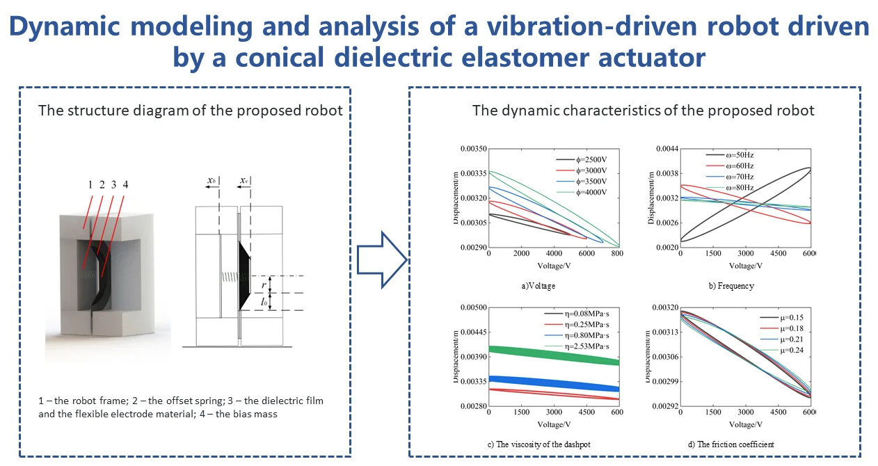
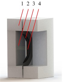
The structure of the vibration-driven robot used in this article is shown in Fig. 1(a). The thin film and electrode design of the conical dielectric elastomer actuator is based on the widely used “sandwich” structure. Its main structure consists of a vibration-driven robot frame, dielectric elastomer film, flexible electrode material, an offset spring, and bias mass. When alternating current is applied, the dielectric elastomer film causes the oscillator to move back and forth, providing a force that varies periodically to the main body, combined with the friction force from the ground to the main body, resulting in unidirectional motion of the oscillator.
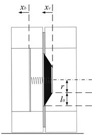
Fig. 1The structure diagram of the proposed robot: 1 – the robot frame; 2 – the offset spring; 3 – the dielectric film and the flexible electrode material; 4 – the bias mass
a) Sectional drawing
b) Schematic diagram
3. Equations of modeling
In this chapter, the nonlinear dynamic model of a conical dielectric elastomer actuator is first derived through the Euler-Lagrange equation. Then, based on the hysteresis model of the conical dielectric elastomer actuator, a dynamic model of a vibration-driven robot driven by a dielectric elastomer is established.
3.1. Modeling of dynamic equations for conical dielectric elastomer actuators
In this section, the Euler-Lagrange equation is used to derive the hysteresis nonlinear dynamic model of a conical dielectric elastomer actuator. The model assumptions proposed in this section are as follows. 1) The system is a single-degree-of-freedom system; 2) The out-of-plane deformation is approximately a cone; 3) The strain distribution on the membrane is uniform; 4) The circumferential strain of the membrane remains unchanged.
The schematic diagram of the vibration-driven robot using a dielectric elastomer driver is shown in Fig. 1(b). The dynamic equation of a dielectric elastomer actuator can be derived from the Euler-Lagrange equation, which is in the following form:
where L=T-V is the Lagrangian quantity, is the kinetic energy of the system, V is the potential energy of the system, qi represents the system state variable, Fi is a non-conservative force in the system, and t represents time.
Assuming that the system mass is much greater than the mass of the DE-film, ignoring the mass of the film, the kinetic energy T of the system can be expressed as:
where, m represents the mass of the oscillator, and d represents the displacement of the oscillator.
The potential energy V of the system is composed of Helmholtz free energy, electrical potential energy, and gravitational potential energy of the dielectric elastomer. The potential energy of the system can be expressed as:
where, l0 is the difference in the outer diameter of the conical dielectric elastomer, λp is the pre-stretching of the dielectric elastomer, r is the internal diameter of the conical dielectric elastomer, z0 is the initial thickness of the dielectric elastomer film, ϕ is the voltage applied to the surface of the dielectric elastomer, and Q is the charge generated after applying the voltage. W is the Helmholtz free energy density of the dielectric elastomer, assuming that the dielectric elastomer film is an ideal elastomer, and its polarization form and rheological material deformation are independent. The Helmholtz free energy density can be expressed as:
Among them, ε is the dielectric constant, λ is the elongation of the dielectric elastomer, D is the electrical displacement of the dielectric elastomer, the first term on the right is the free energy corresponding to the elastic energy generated by the thin film due to stretching, and the second term is the electrostatic energy. Select the Gent model to describe the superelastic properties of dielectric elastic thin films, in the form of:
where μ is the shear modulus, and J is the tensile limit of the material. When the leakage current and other electrical dissipation are not considered, the generalized force of the variable in the Euler-Lagrange equation is zero.
For the viscoelastic model of dielectric elastomers, we combine the Maxwell model with the Voigt model, treating it as a form of stiffness and damping connected in series and then connected in parallel with damping. Eq. (5) can be expressed as follows:
-μβJβlim2log(1-λ21ξ-21+λ22ξ-22+λ-21ξ21λ-22ξ22-3Jβlim),
where, λ1, λ2, ξ1, ξ2 represent the stretches of the spring and dashpot in different directions, and μα, Jαlim, μβ, Jβlim are the shear modulus and the tensile limit of the spring and dashpot.
Subsequently, based on the geometric characteristics of the system, the dynamic equation of the conical dielectric elastomer actuator can be expressed as:
-π(2r+l0)ϕDd√d2+l20=0.
To model the dashpot as a Newtonian fluid, we relate the rate of deformation to the stress as:
where, η is the viscosity of the dashpot.
3.2. Construction of a conical dielectric elastomer vibration driven robot model
In this section, a dynamic model of a vibration driven robot driven by a dielectric elastomer is established. There is an interaction F(xv,xb) between vibrator mv and body mb, which is related to the current position of the mass block xv and the shell xb and the velocity of the mass block ˙xv and the shell ˙xb, while there is friction force f between the shell and the environment, which is the product of friction force and positive pressure, and can be written as μ(mv+mb)gsgn(˙x2). For a general vibration driven robot, its dynamic equation can be expressed as:
According to the conical dielectric elastomer actuator model derived in the previous section, the interactions F(xv,xb) can be divided into mechanical interactions Fm(xv,xb), electric field interactions Fe(xv,xb,t), and hysteresis interactions Fh(xv,xb), represented as:
∙1-1λ6p(((xv-xb)/l0)2+1)21-(λ2p(((xv-xb)/l0)2+1)+λ2p+1λ4p(((xv-xb)/l0)2+1)-3)/J,
∙ξ-2-ξ2λ6p(((xv-xb)/l0)2+1)21-(λ2p(((xv-xb)/l0)2ξ-2+1)+λ2p+ξ2λ4p(((xv-xb)/l0)2+1)-3)/Jβlim.
Introducing dielectric elastomers into the vibration driven robot model, Eq. (9) becomes:
mb¨xb-Fm(xv,xb)-Fe(xv,xb,t)-Fh(xv,xb)=-μ(mb+mv)gsgn(˙xb).
4. Simulation
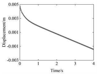
In this section, the dynamic model of the vibration-driven robot established in the previous section is first used to analyze the system response. The periodic voltage varies in a sinusoidal form, with an amplitude and bias of 3000 V and an excitation frequency of 75 Hz. The friction coefficient used is 0.2, the viscosity of the dashpot is set to 0.08 MPa·s. The displacement curve of the main body of the proposed robot is shown in Fig. 2. From the graph, we can see that the system maintains a certain speed in one direction after an initial stage. In the overall movement process, there are also local fluctuations.
Fig. 2Displacement curve of the main body of the proposed robot
a) Overall diagram
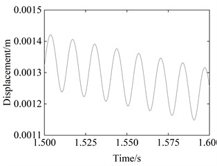
b) Partially enlarged view
Fig. 3Example of figure consisting of multiple charts
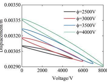
a) Voltage
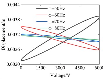
b) Frequency
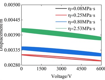
c) The viscosity of the dashpot
d) The friction coefficient
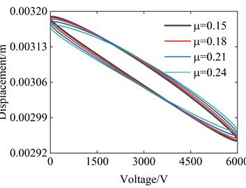
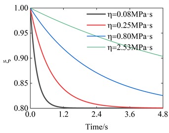
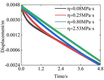
Next, the hysteresis characteristics of the system are analyzed. The hysteresis characteristics between the difference of the main body and the oscillator’s displacement, with the voltage are studied, which to some extent reflects the energy consumption of the system. The influences of different parameters are analyzed here, shown in Fig. 3. It can be seen from the pictures that the voltage affects the size of the hysteresis loop, but has little effect on its shape. Because frequency affects the vibration of the system, it has the greatest impact on the hysteresis loop. And the friction coefficient also has a certain impact on the hysteresis loop, the larger the friction coefficient, the wider the hysteresis loop. The viscosity of the dashpot also has a significant impact on the hysteresis loop, which affects the position of the hysteresis loop. Next, the impact of the viscosity of the dashpot on it is discussed in depth, as shown in Fig. 4. It can be found that as the viscosity of the dashpot decreases, the system will tend to stabilize faster. But before reaching stability, the system moves faster than the stable speed. From Fig. 4(b), we can also find that though a large viscosity will lead to faster stabilization, its motion speed remains constant during the unstable stage.
Fig. 4The stretches of the dashpot curves and the displacement curves of the body considering the viscosity of the dashpot
a) The stretches of the dashpot
b) The displacement of the body
5. Conclusions
This article establishes the dynamic equation of a vibration-driven robot driven by a conical dielectric elastomer actuator from a physical aspect and analyzes its dynamic behavior. The motion response characteristics of the system are derived, and the evolution laws of the hysteresis loop with voltage, frequency, friction coefficient, and the viscosity of the dashpot are obtained. The dynamic model and evolution law can provide optimization and control theoretical basis for subsequent research. In addition, it is found that after introducing the viscoelastic properties of dielectric elastomers, the motion speed of the vibration-driven robot will follow the stretches of the dashpot, and as the viscosity of the dashpot decreases, the system will tend to stabilize faster. But before reaching stability, the system moves faster than the stable speed. This feature allows researchers to choose different materials based on different occasions.
References
-
J. Luo, S. Ye, J. Su, and B. Jin, “Prismatic quasi-direct-drives for dynamic quadruped locomotion with high payload capacity,” International Journal of Mechanical Sciences, Vol. 235, p. 107698, Dec. 2022, https://doi.org/10.1016/j.ijmecsci.2022.107698
-
Z. Yan, K. Wang, and B. Wang, “Mechanical design and analytic solution for unfolding deformation of locomotive ferromagnetic robots,” International Journal of Mechanical Sciences, Vol. 211, p. 106799, Dec. 2021, https://doi.org/10.1016/j.ijmecsci.2021.106799
-
A. Shukla and H. Karki, “Application of robotics in onshore oil and gas industry-A review Part I,” Robotics and Autonomous Systems, Vol. 75, pp. 490–507, Jan. 2016, https://doi.org/10.1016/j.robot.2015.09.012
-
A. Garg et al., “Design and development of in vivo robot for biopsy,” Mechanics Based Design of Structures and Machines, Vol. 42, No. 3, pp. 278–295, Jul. 2014, https://doi.org/10.1080/15397734.2014.898587
-
K. Zimmermann, I. Zeidis, N. Bolotnik, and M. Pivovarov, “Dynamics of a two-module vibration-driven system moving along a rough horizontal plane,” Multibody System Dynamics, Vol. 22, No. 2, pp. 199–219, Sep. 2009, https://doi.org/10.1007/s11044-009-9158-2
-
P. Liu, H. Yu, and S. Cang, “On the dynamics of a vibro-driven capsule system,” Archive of Applied Mechanics, Vol. 88, No. 12, pp. 2199–2219, Dec. 2018, https://doi.org/10.1007/s00419-018-1444-0
-
N. A. Sobolev and K. S. Sorokin, “Experimental investigation of a model of a vibration-driven robot with rotating masses,” Journal of Computer and Systems Sciences International, Vol. 46, No. 5, pp. 826–835, Oct. 2007, https://doi.org/10.1134/s1064230707050140
-
L. Wang, W. Chen, J. Liu, J. Deng, and Y. Liu, “A review of recent studies on non-resonant piezoelectric actuators,” Mechanical Systems and Signal Processing, Vol. 133, p. 106254, Nov. 2019, https://doi.org/10.1016/j.ymssp.2019.106254
-
S. Wang, W. Rong, L. Wang, H. Xie, L. Sun, and J. K. Mills, “A survey of piezoelectric actuators with long working stroke in recent years: Classifications, principles, connections and distinctions,” Mechanical Systems and Signal Processing, Vol. 123, pp. 591–605, May 2019, https://doi.org/10.1016/j.ymssp.2019.01.033
-
X. Zhan, J. Xu, and H. Fang, “A vibration-driven planar locomotion robot-Shell,” Robotica, Vol. 36, No. 9, pp. 1402–1420, Sep. 2018, https://doi.org/10.1017/s0263574718000383
-
A. Nunuparov, F. Becker, N. Bolotnik, I. Zeidis, and K. Zimmermann, “Dynamics and motion control of a capsule robot with an opposing spring,” Archive of Applied Mechanics, Vol. 89, No. 10, pp. 2193–2208, Oct. 2019, https://doi.org/10.1007/s00419-019-01571-8
-
C. Tang, B. Li, H. Fang, Z. Li, and H. Chen, “A speedy, amphibian, robotic cube: resonance actuation by a dielectric elastomer,” Sensors and Actuators A: Physical, Vol. 270, pp. 1–7, Feb. 2018, https://doi.org/10.1016/j.sna.2017.12.003
-
C. Tang, B. Li, C. Bian, Z. Li, L. Liu, and H. Chen, “A locomotion robot driven by soft dielectric elastomer resonator,” in Intelligent Robotics and Applications, pp. 120–126, 2017, https://doi.org/10.1007/978-3-319-65289-4_12
-
C. Cao, R. S. Diteesawat, J. Rossiter, and A. T. Conn, “A reconfigurable crawling robot driven by electroactive artificial muscle,” in 2019 2nd IEEE International Conference on Soft Robotics (RoboSoft), pp. 840–845, Apr. 2019, https://doi.org/10.1109/robosoft.2019.8722789
-
Yangyang Du, Chongiing Cao, Xiaojun Wu, Jiasheng Xue, Lei Wang, and Xing Gao, “A low-profile vibration crawling robot driven by a planar dielectric elastomer actuator,” 2022 IEEE International Conference on Real-time Computing and Robotics (RCAR), pp. 413–418, 2022.
Cited by
About this article
This work was supported by the National Natural Science Foundation of China [Grant number 11972222].
The datasets generated during and/or analyzed during the current study are available from the corresponding author on reasonable request.
The authors declare that they have no conflict of interest.
