Abstract
Pneumatic spring dampers are extensively utilized within hydraulic systems, and the flow characteristics of the internal oil play a crucial role in determining noise and vibration levels. To validate the mechanical structure's reliability, the shock absorber was simplified and the fluid domain was extracted using a CFD method. The velocity field and pressure field under different conditions were then simulated and analyzed. A finite element model of the flow field was established, and its accuracy was verified by comparing simulation results of gas side pressure with experimental results. According to the working principle of the oil-gas spring, dynamic active surfaces in contact with the main piston and dynamic driven surfaces in contact with the floating piston were defined, determining moving conditions for dynamic grids. The results indicate that as the diameter of flow channels increases, there is a decrease in average pressure drop within the oil chamber (i.e., pressure loss within the flow field). Additionally, as bend angle increases, average pressure drop decreases. However, optimization effects become less significant beyond a certain bend angle.
Highlights
- To validate the mechanical structure's reliability, the shock absorber was simplified and the fluid domain was extracted using a CFD method.
- The velocity field and pressure field under different conditions were then simulated and analyzed.
- A finite element model of the flow field was established, and its accuracy was verified by comparing simulation results of gas side pressure with experimental results.
1. Introduction
Shock absorber is one of the most important parts to reduce the vibration and noise of mechanical equipment [1, 2]. Oil-gas spring shock absorber is widely used in hydraulic system. It has a large number of complex parts, but most of these parts belong to the external structural parts of the oil-gas spring and have little influence on the internal basin. Only the damper valve component will change the shape of the basin and then affect the flow field characteristics [3]. In order to further improve the damping adjustment function, the damper valve component can be removed on the basis of the original geometric structure of the oil-gas spring, and the internal basin of the improved oil-gas spring can be analyzed and studied. Considering the working principle, working process and flow field calculation process of the oil-gas spring, the structure of the oil-gas spring is reasonably simplified in the process of fluid domain extraction, and the efficiency of modeling and calculation is improved on the basis of ensuring the accuracy of modeling [4, 5]. In the actual working process of the oil-gas spring shock absorber, there must be a very small gap between the main piston and the oil outer shell, the floating piston and the air outer shell due to the existence of processing errors, so there are problems of oil leakage and oil and gas mixing [6]. However, these problems are not the focus of the study, so the gap between the piston and the housing is ignored, and the two are considered to be closely fitted. The biggest difference between feed-energy shock absorber and traditional shock absorber is the introduction of energy recovery device, that is, energy feed device, which can not only provide vibration damping but also convert vibration energy into other usable energy forms. Therefore, the dynamic characteristics of different structures of shock absorbers need to be simulated and analyzed for different fields of application basis.
2. The establishment of finite element model
2.1. Flow field modeling and validation
The chamfer of various sizes in the shock absorber structure will increase the complexity of mesh division and reduce the calculation efficiency, but it has little impact on the overall finite element calculation result, so some unnecessary chamfer is removed. After simplifying and refining the geometric structure in Hypermsh, the resulting structural model and internal drainage model are depicted in Fig. 1. The internal basin consists of two components: the oil basin and the gas basin. The oil drainage basin refers to the internal flow pathway of the primary oil chamber in contact with the main piston, as well as the secondary oil chamber in contact with the floating piston. The gas basin pertains to a section of the gas chamber.
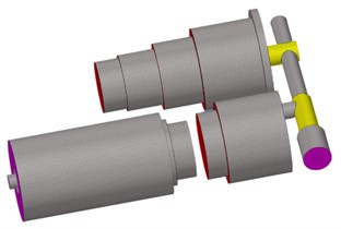
The simplified fluid domain model of the shock absorber is meshed in Hypermesh to establish the finite element model. Due to the geometric structure of the oil and gas chamber basin being a combination of several cylinders, hexahedral meshing is suitable for the cylinder structure [7]. Additionally, considering the applicability of the lay-up method for dynamic meshing, the fluid domain geometric model of the oil chamber and gas chamber is divided into hexahedral mesh in Hypermesh. The finite element models of the oil chamber, flow channel, and gas chamber after division are shown in Fig. 2.
Fig. 1The composition of finite element model
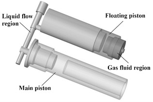
Fig. 2Meshing result
2.2. Verification of model accuracy
The pressure of the air chamber varies non-linearly with the displacement of the piston, which is a key characteristic of the elastic force provided by the oil-gas spring. During the compression stroke, the non-linear elastic force from the air chamber can increase resistance as compression increases, thereby reducing compression speed and shortening compression time under actual road load. In the established finite element model, the gas density in the gas chamber is set as an ideal gas, and the gas attribute is nitrogen. The static characteristics of the model were simulated to reflect the elastic force characteristics of the gas. In the analysis of nonlinear elastic force, the oil pressure change is ignored and the liquid is regarded as an incompressible fluid. The comparison of gas pressure simulation results and measured results is shown in Fig. 3. It can be seen that the gas pressure in the gas chamber based on the established oil-gas spring fluid domain simulation has a certain fluctuation, which may be related to the instability of the transient calculation of Fluent after the grid setting is started, and may also be related to the grid quality. However, in general, the simulated gas pressure is obviously non-linear with piston displacement, which is consistent with the expected theory. In conclusion, the elastic force characteristics of the gas chamber calculated by the finite element model simulation based on the constructed internal drainage basin are in line with theoretical expectations and actual performance. Therefore, it is considered that the finite element model demonstrates good feasibility and reasonable parameter settings, laying a solid foundation for subsequent flow field simulations.
Fig. 3Model verification result
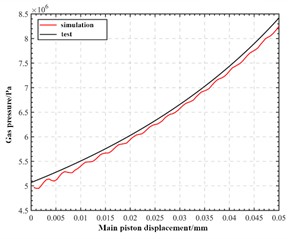
a) Pressure result verification
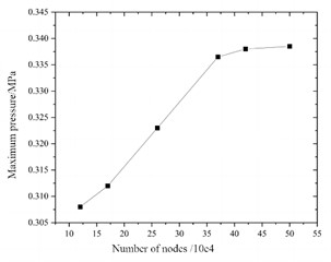
b) Mesh result verification
2.3. Setting of dynamic boundary conditions
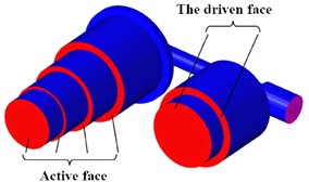
The external road load directly acts on the main piston, causing it to compress or stretch outwards and move the internal fluid. Assuming no oil leakage, the model's interior is a closed system with a constant total amount of oil. The bottom wall surface of the main oil chamber, in contact with the main piston, consists of a round surface and three tori, serving as an active surface stimulated by external forces to induce oil flow. The bottom wall of the auxiliary oil chamber, in contact with the floating piston, includes a circular surface and a torus, acting as a driven surface moved by combined oil and gas pressure on the other side, as shown in Fig. 4. Similarly, for the gas basin, the top wall of its chamber in contact with the floating piston comprises a circular surface and two tori that are also moved by combined oil and gas pressure. These driving surfaces on one side and driven surfaces on another define key factors for defining dynamic boundary surfaces for fluid motion. The turbulence model employed is the SST turbulence model, which combines the advantages of both the k-ω and k-ε models.
Fig. 4Model verification result
3. Influence of structural parameters on dynamic characteristics
3.1. The influence of runner diameter
According to the working principle, the local pressure loss of the model can be divided into three categories. The first type is the local pressure loss caused by the sudden reduction of the round tube, which occurs in the place where the main oil chamber and the longitudinal flow passage are connected. The second type is the local pressure loss caused by the sudden expansion of the round tube, which occurs in the place where the longitudinal flow passage and the auxiliary oil chamber are connected. The third type is the local pressure loss caused by the bending of the round pipe, which occurs at the intersection of the longitudinal and transverse channels inside the flow channel. The ratio of the diameter of the main and auxiliary oil chambers to the diameter of the flow channel not only directly determines the first and second kinds of local pressure loss coefficients. At the same time, it will also lead to the change of flow rate, and then affect the third type of local pressure loss coefficient. When the diameter of the main and secondary oil chambers is given, the diameter of the flow path becomes the key parameter affecting the local pressure loss.
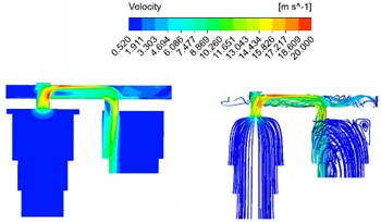
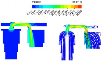
Response results of velocity field under different diameters are shown in Fig. 5. It can be seen that the flow rate in most areas of the model is relatively gentle, and the flow rate is basically maintained at the same level as the movement speed of the main piston, while the flow rate near the flow channel area is rapidly accelerated, with a maximum speed of 22.784 m/s, reaching 43.82 times of the peak speed of the main piston. In general, in the compression stroke, the flow rate increases sharply when entering the flow passage from the main oil chamber due to the sudden reduction of the cross-sectional area of the pipeline, and the maximum speed is reached at the bend of the flow passage. The transverse flow speed of the oil in the flow passage is basically unchanged, and the high speed in the flow passage is maintained when entering the secondary oil chamber from the flow passage and flows into the secondary oil chamber at a speed of almost vertical cross section of the oil chamber. With the increase of the diameter of the runner, the maximum velocity at the bend of the runner decreases obviously.
Fig. 5Response results of velocity field under different diameters
a) 18 mm
b) 22 mm
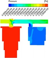
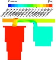
Response results of pressure field under different diameters are shown in Fig. 6. The internal pressure distribution showed obvious stage characteristics. The main oil chamber in contact with the active surface is the first to be affected by the internal compression of the main piston and is the starting position of pressure propagation, so it can be seen that the pressure in the main oil chamber is the highest. As the oil enters the flow channel, local resistance is encountered at the junction of the main oil chamber and the flow channel and at the bend in the flow channel, and the pressure is reduced, and the lowest pressure appears at the bend of the second flow channel. When the oil enters the auxiliary oil chamber from the flow passage, it can be seen that the local flow velocity within a certain diameter is still high in fact, and there is no great change, so the pressure reduction is not significant from the pressure cloud image. With the increase of the diameter of the flow passage, the maximum pressure of the main oil chamber decreases gradually, and the pressure drop between the main oil chamber and the flow passage and the total pressure drop also decrease gradually.
Fig. 6Response results of pressure field under different diameters
a) 18 mm
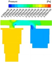
b) 22 mm
3.2. Impact of vibration reduction design on benefits
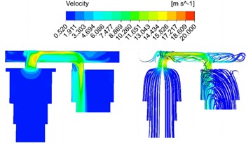
The bending angle of the runner is shown in Fig. 7. In order to specifically study the influence of the flow field on the bend angle of the flow channel, the bend angle of the flow channel is set to 100 degree and 130 degree respectively, and the velocity field analysis results under different structural conditions are obtained as shown in Fig. 8. It is evident that the bending angle not only impacts the maximum flow velocity within the passage, but also influences the distribution of high flow velocity areas, and plays a crucial role in directing oil flow from the passage into the auxiliary oil chamber. As the bend angle increases, there is a gradual decrease in maximum flow rate within the channel, albeit minimal. Thus, it can be inferred that the effect of changing bend angle on maximum flow rate is quite limited. Response results of pressure field under different bending angle are shown in Fig. 9. It can be seen that the average pressure drop of the oil chamber increases with the increase of the movement speed of the main piston, and gradually decreases with the increase of the flow channel bending Angle. Similarly, the equivalent pressure loss coefficient decreases with the increase of the flow channel bending Angle. When the bending Angle increases to about 130°, the flow pressure loss in the oil-gas spring can be reduced to the greatest extent, and the effect is limited if the bending Angle continues to increase. Simultaneously, as the bending angle increases, a low flow velocity area gradually emerges near the longitudinal flow channel wall at the first bend and expands. The low flow velocity area near the longitudinal channel wall decreases gradually at the second bend, and the average flow velocity leaving the channel initially decreases and then increases due to the influence of high and low flow velocity areas.
Fig. 7Definition of bending angle
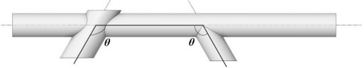
Fig. 8Response results of velocity field under different bending angle
a) 100 degree
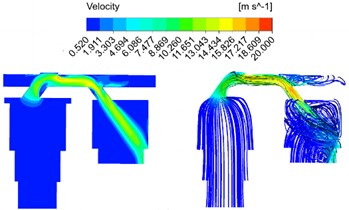
b) 130 degree
Fig. 9Response results of pressure field under different bending angle
a) 100 degree
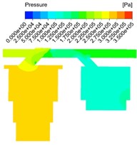
b) 130 degree
The flow rate and pressure are the primary factors influencing the damping force of shock absorber. An increase in equivalent pressure loss will lead to a rise in damping force, resulting in a higher proportion of viscous damping. By simulating and analyzing the impact of structural modifications on flow rate and pressure, the improved runner diameters and bending angles can be derived, which play a pivotal role in reducing pressure loss and enhancing the operational efficiency of shock absorber. In practical applications, the optimized structure ensures more rapid reduction of vibration and amplitude attenuation during stroke.
4. Conclusions
1) The velocity of the oil in the hydraulic cylinder, driven by the high-speed piston, will exceed that of the piston itself. The analysis of damping characteristics under different structural parameters should be conducted based on a reasonable turbulence model. It ensures stability in near-wall solutions, exhibits independence from the outer boundary layer, demonstrates excellent computational performance, and requires less computation than the more complex Reynolds stress model.
2) The structural configuration significantly impacts the dynamic damping properties. The average pressure drop and equivalent pressure loss coefficient of the oil chamber decrease as the flow channel diameter and bend angle increase, but the specific trends differ, with the flow channel diameter having the most significant influence.
References
-
S. V. Sharma, H. Gladston, and A. Ebanesar, “Effect of piston displacement on performance of an MR damper for structural application,” Practice Periodical on Structural Design and Construction, Vol. 29, No. 3, pp. 102–114, Aug. 2024, https://doi.org/10.1061/ppscfx.sceng-1493
-
M. J. Rezvani and H. Souzangarzadeh, “Performance of end-capped multi-segmented conical tubes filled with foam under axial and oblique loads as an energy absorber,” Journal of the Brazilian Society of Mechanical Sciences and Engineering, Vol. 46, No. 6, pp. 188–198, May 2024, https://doi.org/10.1007/s40430-023-04581-4
-
R. Talebitooti, M. Zarastvand, and H. Darvishgohari, “Multi-objective optimization approach on diffuse sound transmission through poroelastic composite sandwich structure,” Journal of Sandwich Structures and Materials, Vol. 23, No. 4, pp. 1221–1252, Jun. 2019, https://doi.org/10.1177/1099636219854748
-
H. Dong, Y. Li, K. Bi, Q. Han, and X. Du, “Seismic performance assessment of RC bridge piers with variable hysteresis performance dampers,” Engineering Structures, Vol. 310, No. 1, p. 118085, Jul. 2024, https://doi.org/10.1016/j.engstruct.2024.118085
-
M. Niazi, S. N. Ashrafizadeh, S. H. Hashemabadi, and H. Karami, “CFD simulation of drag-reducing fluids in a non-Newtonian turbulent pipe flow,” Chemical Engineering Science, Vol. 285, No. 11, p. 119612, Mar. 2024, https://doi.org/10.1016/j.ces.2023.119612
-
R. Ahammed and M. Z. Hasan, “An FEA and CFD coupled numerical analysis approach for characterizing magneto-rheological (MR) grease damper,” Sādhanā, Vol. 48, No. 3, pp. 44–57, Aug. 2023, https://doi.org/10.1007/s12046-023-02196-y
-
A. Das, T. Konar, D. Maity, and S. K. Bhattacharyya, “Revisiting equivalent tuned mass damper analogy for tuned liquid damper utilizing CFD-FEA framework,” Soil Dynamics and Earthquake Engineering, Vol. 172, No. 6, p. 108051, Sep. 2023, https://doi.org/10.1016/j.soildyn.2023.108051
About this article

The paper is supported by Shandong Province undergraduate teaching reform research project (project number: M2020307).
The datasets generated during and/or analyzed during the current study are available from the corresponding author on reasonable request.
The authors declare that they have no conflict of interest.
