Abstract
A structural diagram of a vibratory drum separator has been developed, and based on it, a mathematical model of the separator’s oscillatory motion has been constructed. The mathematical model was built using nonlinear mechanics methods and Lagrange equations. The obtained dependencies allow for determining the influence of geometric and physico-mechanical parameters on various factors affecting the intensity of the separation process. The research results should be used both at the design stages of vibratory separators and when selecting their parameters and operational modes.
Highlights
- Based on the conducted analysis, parameters such as imbalance eccentricity, the magnitude of the unbalanced rotating mass, air suspension stiffness, and the angular speed of imbalance rotation critically influence the intensity of separation.
- When the angular velocity of the unbalance rotation increases from 50 s-1 to 150 s-1 (a 3-fold increase), the amplitude decreases by approximately 1.67 times (from 4.5 mm to 2.7 mm) with the unbalance mass of 4 kg.
- The intensity of separation depends non-linearly on the unbalance eccentricity and increases with its growth (see Fig. 7). Specifically, with an increase from 0.01 m to 0.05 m (5 times), the amplitude of the screen oscillations increased from 1.6 to 4 mm – by 2.5 times.
1. Introduction
The rapid development of industry necessitates the modernization of existing equipment and the creation of new machinery to optimize technological processes. The variety of technologies expands the range of implemented operations that ensure the sorting of crushed material by its geometric dimensions. This necessitates research and improvement of the design of separating equipment, particularly that used in the vibrational separation of bulk materials. Such equipment includes vibrational separators, sorting machines, and screens, which are used in various fields of industry and agriculture and have extensive applications in production. They perform the removal of impurities and the sorting of various products by size, density, coefficient of friction, elasticity, and other physical and mechanical characteristics. One type of vibrational separator is the drum vibrational separator. It is used for fractionated division of products, cleaning (removal and reduction of impurities in materials) and ensures high-quality separation. Researching the operation of such separators and creating a mathematical model to describe the dynamics of the separator will enable the selection of optimal design parameters, operating modes, and optimization of the separation process.
2. Referencing
In [1-3], it is established that separators with movable screens exhibit significantly higher productivity due to better interaction between the screen and the separated mixture. The concentric arrangement of screens in drum-type separators [4] enables their application as separator-conveyors, simultaneously providing separation and transfer of the separated fraction. However, the design of separators with movable screens constitutes a complex dynamic system that requires thorough theoretical investigation through mathematical modeling.
Current mathematical models describing the dynamics of separators are limited within certain boundaries. For instance, [5-7] explore the dynamics of isolated components of the separator, while [8] considers the dynamic separation process in a linear formulation, limiting its applicability. In [9] a mathematical model of the separator using numerical methods is described.
The creation of a model for a vibratory processing system [10, 11], formulated as a set of analytical expressions, allows for a more detailed description of the dynamic processes occurring in the oscillatory system. These expressions encompass key parameters of such systems, including kinematic, geometric, and force parameters. Therefore, expanding research and developing a mathematical model of a vibratory separator based on nonlinear mechanics methods remains a relevant task.
3. Main material
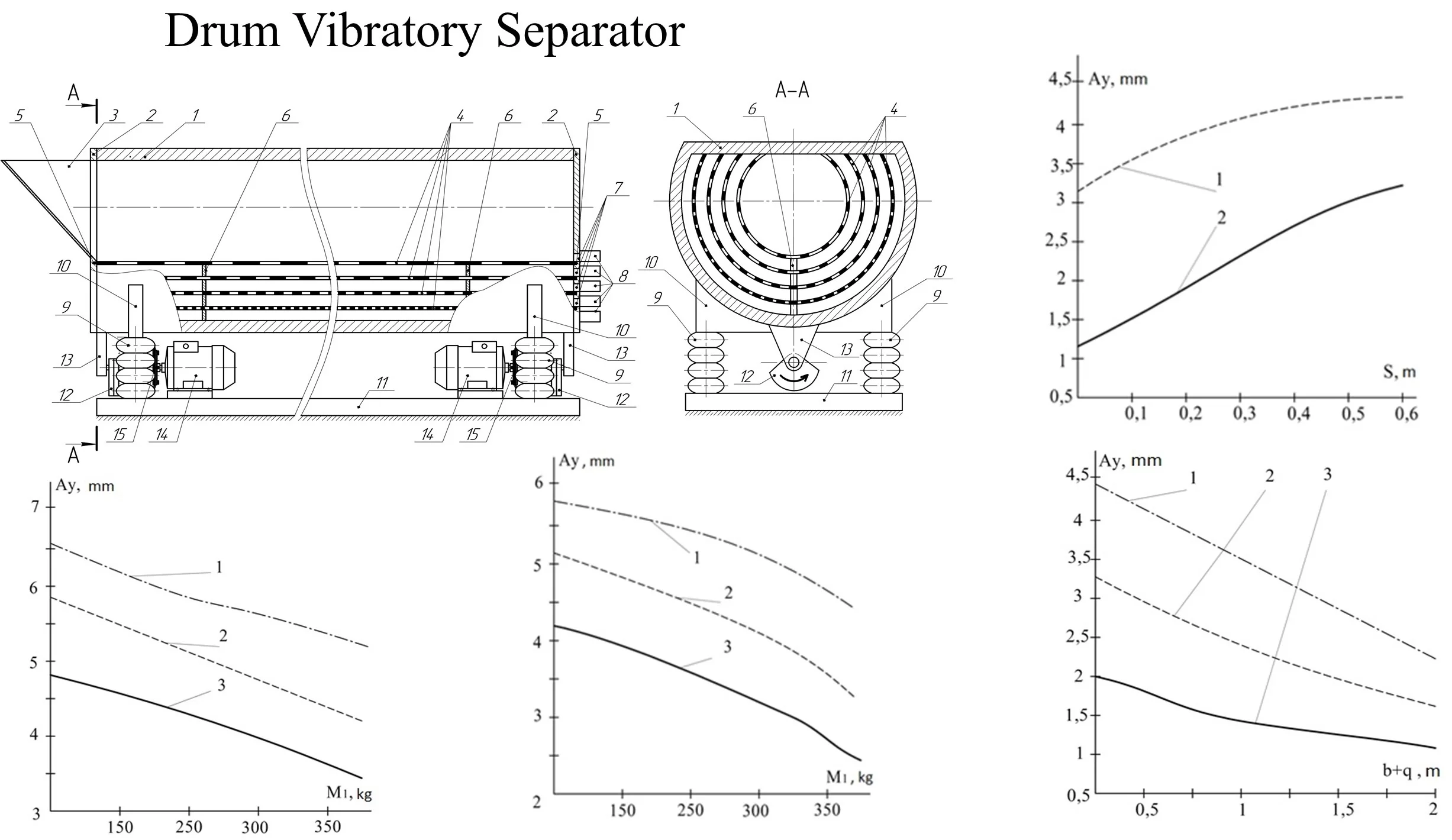
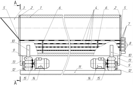
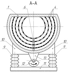
The drum vibratory separator under investigation is depicted in Fig. 1. The separator includes a drum with a loading hopper at one end, screens positioned inside the drum, pneumatic suspension, and a vibratory drive. The drum and screens have a truncated cylindrical shape, with the upper part of their lateral surface parallel to the horizontal plane. The drum is attached to the frame using a dual pneumatic suspension system. It is actuated by a vibratory drive consisting of two symmetrically placed unbalances located beneath the drum at its opposite ends. The rotary motion of these unbalances is facilitated through elastic couplings from electric motors mounted on the separator frame.
Fig. 1Drum vibratory separator: a) main view; b) side view (section): 1 – drum, 2 – drum ends, 3 – loading hopper, 4 – screens, 5 – grooves, 6 – plate supports, 7 – holes with plugs, 8 – trays, 9 – pneumatic suspension, 10 – support, 11 – frame, 12 – unbalance, 13 – protrusion, 14 – electric motor, 15 – elastic coupling.
a)
b)
The execution of the drum and screens in the form of a truncated cylinder, with the upper part of its lateral surface parallel to the horizontal plane, allows for a reduction in the oscillating mass of the separator by removing the portion of the screens and drum that do not participate in the separation process.
The presence of a pneumatic suspension enables a simple and smooth adjustment of the suspension stiffness, and consequently, the amplitude of the separator's oscillations. This adjustment is achieved by smoothly changing the air pressure in the suspension's pneumatic cylinders. Specifically, when the drive motors are turned on and off, the suspension stiffness should be minimized to allow the separator to pass through the resonance zone (as vibratory machines of this type operate in a post-resonance zone) at the lowest possible frequency. This reduces the operational load on the separator’s moving parts and assemblies, which is maximal when passing through resonance. By passing through resonance at a low frequency, the loads induced by resonance will also be lower, ensuring normal operating conditions with less power from the drive motors. Consequently, this results in lower energy consumption for operating the separator and reduces the required strength and material usage for its supports.
Additionally, smooth regulation of the separator's oscillation amplitude (one of the key factors affecting separation efficiency) by gradually adjusting the suspension stiffness, even during the separator's operation, enhances its versatility. This allows for the selection of the most effective separation mode according to the type of mixture, its volume, mass, and other factors.
The placement of the loading hopper at the end of the drum opposite to the end with the openings for collecting separated fractions into trays allows the mixture to be loaded into the inner screen along the inclined surface of the hopper at an angle to the horizontal under the influence of gravity and hopper vibrations. This setup prevents the phenomenon of particle impact against the inner screen, thereby avoiding their damage due to excessive fragmentation.
Based on the presented scheme of the vibratory separator, a mathematical model describing the oscillatory motion of the separator's screen system in planes parallel to the planes of the rotational motion of the pair of drive unbalances (in the planes of the transverse section of the screens) has been developed using asymptotic methods of nonlinear mechanics [12] and Lagrange equations. The model is represented as a system of parametric analytical dependencies Eqs. (1-3) of the generalized coordinates describing the oscillatory motion of an arbitrary transverse section of any screen of the separator, depending on the separator's parameters – kinematic, geometric, and force:
where, the following notations are used: , – coordinates of the center of mass of the screen's cross-section; – angle of its rotation in oscillatory motion; 255 kg– the mass of the loaded screen system; 4 kg – the mass of the unbalance; 0.04 m – distance between the center of mass of the unbalance and its center of rotation (unbalance eccentricity); 20 kN/m – total stiffness of the left and right suspension spring systems and ; – angular velocity of the unbalances; 10° – polar angle of the coordinate system associated with the moving cross-section of the screen relative to its initial position; , 1.4 m, , 0.5 m – pairs of horizontal and vertical coordinates of the left and right suspension points of the separator relative to the center of mass of the screen cross-section, respectively; 0.1 m – distance between the axis of rotation of the unbalance and the axis of the separator screen.
According to the input data, the graphs (see Figs. 2-7) depict the influence of the parameters of the vibratory separator with horizontal layering of screens on the amplitude of the oscillatory motion of its screen, which is a key factor in the efficiency of the separation process. In particular, the impact of the vertical component of the amplitude is considered, as it is responsible for lifting the mixture with the screen and the intensity of their interaction.
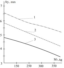
Fig. 2The dependence of the vertical component of the amplitude of oscillations of the vibratory separator on the oscillating mass at an angular velocity of the unbalances ω1 =100 s-1: 1 – suspension stiffness 10 kN/m, 2 – 13 kN/m, 3 – 16 kN/m
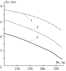
Fig. 3The dependence of the vertical component of the amplitude of oscillations of the vibratory separator on the oscillating mass at an angular velocity of the unbalances ω2 =50 s-1: 1 – suspension stiffness 10 kN/m, 2 – 13 kN/m, 3 – 16 kN/m
Using the constructed graphical dependencies, based on the developed mathematical model of the vibratory separator with concentric screen arrangement, quantitative conclusions can be drawn about the influence of its parameters on the intensity of separation.
The amplitude of the separator screen oscillations depends on the mass of the mixture on the screen and decreases with an increase in this mass (see Fig. 2). The dependence is nonlinear. Specifically, for example, when the oscillating mass of the separator increases from 150 to 350 kg (approximately 2.33 times), the amplitude decreases by 1.44 times (from 3.9 mm to 2.7 mm). Here, the angular velocity of the unbalance rotation is 100 s-1, and the suspension stiffness is 16 kN/m. Other system parameters remain constant.
The amplitude of the separator screen oscillations depends on the angular velocity of the unbalance rotation (see Fig. 2, Fig. 3). It decreases nonlinearly with increasing angular velocity. For example, when the angular velocity increases from 50 s-1 to 100 s-1 (a 2-fold increase), the amplitude decreases by approximately 1.18 times (from 4.6 mm to 3.9 mm). In this example, the oscillating mass is 150 kg, and the suspension stiffness is 16 kN/m. Other system parameters are constant.
Analyzing the graph shown in Fig. 6, when the angular velocity of the unbalance rotation increases from 50 s-1 to 150 s-1 (a 3-fold increase), the amplitude decreases by approximately 1.67 times (from 4.5 mm to 2.7 mm) with the unbalance mass of 4 kg.
The intensity of separation is nonlinearly dependent on the stiffness of the separator's suspension. It decreases with increasing stiffness. For instance, when the suspension spring stiffness of the separator increases from 8 kN/m to 18 kN/m (by 2.25 times), the oscillation amplitude of the screen (separation intensity) decreases by 2.3 times (from 3.2 mm to 1.4 mm) with an unbalance eccentricity of 0.02 m. Other system parameters remain constant.
Fig. 4Dependence of the oscillation amplitude of the vibratory separator on the suspension position: 1 – oscillating mass 100 kg, 2 – oscillating mass 200 kg, 3 – oscillating mass 300 kg
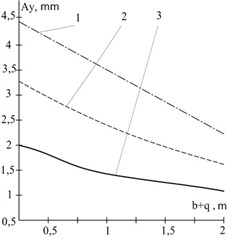
Fig. 5Dependence of the oscillation amplitude of the vibratory separator on the unbalance position: 1 – oscillating mass 180 kg, 2 – oscillating mass 360 kg
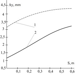
Fig. 6The dependence of the vertical component of the oscillation amplitude of the vibratory separator on the angular velocity of the unbalances: 1 – unbalanced mass 4 kg, 2 – 3 kg, 3 – 2 kg, 4 – 1 kg
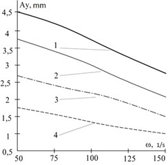
Fig. 7The dependence of the vertical component of the oscillation amplitude of the vibratory separator on the unbalance eccentricity: 1 – unbalanced mass 4 kg, 2 – 3 kg, 3 – 2 kg, 4 – 1 kg
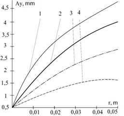
The intensity of separation depends non-linearly on the unbalance eccentricity and increases with its growth (see Fig. 7). Specifically, with an increase from 0.01 m to 0.05 m (5 times), the amplitude of the screen oscillations increased from 1.6 to 4 mm – by 2.5 times. The unbalanced rotating mass of the imbalance is 3 kg. Other system parameters are constant.
The intensity of separation depends non-linearly on the unbalanced rotating mass of the imbalance and increases with its growth (see Fig. 6, 7). Specifically, with an increase in the unbalanced rotating mass of the imbalance from 1 kg to 4 kg (4 times), the amplitude of the oscillatory motion increased from 1.55 mm to 4.2 mm – by 2.7 times at an angular speed of imbalance rotation of 75 Hz. Other system parameters are constant.
Now let’s analyze the impact on the amplitude of oscillations and the intensity of separation of the geometric parameters of the separator with horizontal layering of screens. The intensity of separation depends non-linearly on the spacing of the suspension springs – the parameter (see Fig. 4). For a separator with an oscillating part of 200 kg, with an increase in the distance between the springs from 0.5 m to 2 m (4 times), the amplitude of screen oscillations decreased from 3 to 1.6 mm – 1.9 times. Therefore, we conclude that increasing the distance between supports in the separator in the plane of the imbalance rotational motion leads to a decrease in the intensity of separation, with other system parameters unchanged.
The intensity of separation is non-linearly dependent on the placement of the imbalance's rotational axis (see Fig. 5). With an increase in this parameter (when the imbalance axis is raised structurally upward relative to the screen) in a separator with an oscillating mass of 360 kg from 0 to 0.6 m, the amplitude of the separator’s oscillatory motion increases from 1.15 mm to 3.25 mm, i.e., 2.83 times.
Thus, based on the conducted analysis, parameters such as imbalance eccentricity, the magnitude of the unbalanced rotating mass, air suspension stiffness, and the angular speed of imbalance rotation critically influence the intensity of separation. The first two parameters (imbalance eccentricity, the magnitude of the unbalanced rotating mass) can be easily adjusted during the operation of the separator by using a variable imbalance drive system. The geometric parameters of the separator (the placement of the air suspension and the placement of the imbalance’s rotational axis) also affect the intensity of separation. However, these are not operational parameters when determining separation modes. They should be considered at the design stage of the separator with horizontal screen layering.
4. Conclusions
A key factor in the separation speed is the amplitude of the screen oscillations and the frequency of these oscillations. Based on practical experience in operating vibratory technological systems, the oscillation amplitude of the system is influenced by the magnitude of the oscillating mass, the value of the disturbing force, the stiffness of the suspension of the vibratory technological machine, and the structural features of the entire system.
According to the input data, the constructed motion model of the separator, and the applied software, the influence of the parameters of the drum-type vibratory separator on the amplitude of its screen oscillations, as a determining factor in the efficiency of the separation process, has been reproduced.
The obtained research results can be applied in the development of designs for drum vibratory separators with concentric screen arrangements and in selecting effective operating modes to ensure the maximum intensity of the separation process.
References
-
K. Lawinska and R. Modrzewski, “Analysis of sieve holes blocking in a vibrating screen and a rotary and drum screen,” Physicochemical Problems of Mineral Processing, Vol. 53, pp. 812–828, Jan. 2017, https://doi.org/10.5277/ppmp170212
-
V. Topilnytskyy et al., “Modeling the dynamics of vibratory separator of the drum type with concentric arrangement of sieves,” Eastern-European Journal of Enterprise Technologies, Vol. 2, No. 7(86), pp. 26–35, Apr. 2017, https://doi.org/10.15587/1729-4061.2017.95615
-
J. Li, Q. Zeng, J. Deng, H. Shen, and K. Xiong, “Screening process analysis for multi-dimensional parallel vibrating screen and optimization of screen surface movement,” Transactions of the Chinese Society for Agricultural Machinery, Vol. 47, pp. 399–407, 2016, https://doi.org/10.6041/j.issn.1000-1298.2016.11.054
-
D. Rebot and V. Topilnytskyy, “Drum vibrating separator,” Utility model patent No. 153808, 2024.
-
Z. Lyu and S. Zhou, “Research on spatial Lissajous trajectory vibrating screen,” Advances in Mechanical Engineering, Vol. 11, No. 8, p. 168781401987285, Aug. 2019, https://doi.org/10.1177/1687814019872851
-
A. Shkut, “Research on the dynamics of transitional regimes in an inertial screen with two motor vibrators,” Collection of Research Papers of the National Mining University, Vol. 75, pp. 203–213, Dec. 2023, https://doi.org/10.33271/crpnmu/75.203
-
V. Franchuk, O. Antsiferov, and A. Shkut, “Dynamics of a vibrating screen with two motor-vibrators,” in IOP Conference Series: Earth and Environmental Science, Vol. 1348, No. 1, p. 012063, May 2024, https://doi.org/10.1088/1755-1315/1348/1/012063
-
V. G. Topilnytskyy, M. B. Sokil, D. P. Rebot, and J. M. Kysyy, “Modeling of dynamical loading processes in technological vibratory machines,” Journal of Lviv Polytechnic National University "Dynamics, Strength and Design of Machines and Devices", Vol. 866, pp. 92–98, 2017.
-
G. Shen, Z. Chen, X. Wu, Z. Li, and X. Tong, “Stepwise shape optimization of the surface of a vibrating screen,” Particuology, Vol. 58, pp. 26–34, Oct. 2021, https://doi.org/10.1016/j.partic.2021.01.009
-
D. Rebot, V. Topilnytskyy, T. Stefanovych, and S. Shcherbovskykh, “Vibration oscillations modeling for printed boards of machine control units during their operation,” in 2023 17th International Conference on the Experience of Designing and Application of CAD Systems (CADSM), pp. 1–4, Feb. 2023, https://doi.org/10.1109/cadsm58174.2023.10076529
-
D. Rebot, T. Stefanovych, and S. Shcherbovskykh, “Mathematical model for plate elastic properties studying based on its amplitude-frequency characteristics,” in IEEE 28th International Seminar/Workshop on Direct and Inverse Problems of Electromagnetic and Acoustic Wave Theory (DIPED), pp. 204–207, Sep. 2023, https://doi.org/10.1109/diped59408.2023.10269516
-
L. Yan, Y. Li, M. Cheng, M. Wang, and P. Liu, “Study on nonlinear vibration of vertical lifting section of bulk grain entrainment ship unloader,” Applied Sciences, Vol. 13, No. 20, p. 11213, Oct. 2023, https://doi.org/10.3390/app132011213
About this article

The authors have not disclosed any funding.
The datasets generated during and/or analyzed during the current study are available from the corresponding author on reasonable request.
The authors declare that they have no conflict of interest.
