Abstract
In this paper, the finite element analysis method is used to extensively study the response of rockfall impact on pipelines with different erosion resistant coating. Based on the numerical results, the safety of the pipeline is comprehensively evaluated. Firstly, through the establishment of detailed pipeline and rockfall models, the impact of different rockfall materials and speeds on the pipeline is simulated. The results of the finite element analysis indicate that rockfall impact can cause significant stress concentration and deformation in the pipelines and damage to the coating. With the increment of impact speed, the damage to the pipeline also increases significantly, and different rockfall materials exhibit varying damage conditions, and it is found that fibreglass reinforced epoxy is better than the polyethylene coating. By comparing the analysis results under different conditions, the safety threshold of the pipeline under various rockfall impact scenarios is obtained. This provides an important theoretical basis and reference for the protection design and safety maintenance of the pipeline. The research in this paper not only aids in deepening the understanding of the mechanism of rockfall impact on pipelines but also serves as a valuable reference for improving the safety and reliability of pipeline engineering.
1. Introduction
With the rapid development of global infrastructure construction, especially in the construction of pipeline projects in mountainous areas and other geologically complex areas, rockfall impact has become an important problem threatening pipeline safety. Rockfall impact may not only lead to pipeline damage and leakage, but also trigger a chain reaction, which has a serious impact on the ecological environment and human life. Therefore, it is necessary and practical significance to conduct in-depth research on rockfall impact pipeline and evaluate the safety of pipeline by using finite element analysis technology [1].
Firstly, to study the finite element analysis of rockfall impact pipeline is the key to prevent and reduce pipeline safety accidents. Through finite element analysis, the whole process of rockfall impact pipeline can be simulated, the interaction mechanism between rockfall and pipeline can be revealed, and the stress distribution, deformation law and failure mode of pipeline can be analyzed. This helps us to predict and evaluate the safety of pipeline under rockfall impact more accurately, and provides scientific basis for formulating effective protective measures [2]. Secondly, the development of finite element analysis technology provides a powerful tool for the research of rockfall impact pipeline. Traditional pipeline safety assessment methods are often based on empirical formula or simplified models, which are difficult to accurately reflect the complexity and diversity of rockfall impact. However, finite element analysis can build a more refined model, taking into account the influence of many factors, such as the shape and speed of falling rock, as well as the material and structure of the pipeline. This makes the predicted results more accurate and reliable, and helps to improve the accuracy and reliability of pipeline safety assessment. In addition, with the intensification of global climate change and the frequent occurrence of natural disasters, the problem of falling rocks impacting pipelines has become increasingly prominent. The in-depth study of this problem not only helps to ensure the safe operation of the current pipeline project, but also provides useful reference for the future pipeline design and construction.
The research on rockfall impact pipeline has achieved remarkable results recently. Using the finite element analysis technique, researchers have simulated and analyzed the process of rockfall impact pipeline in detail, and put forward a variety of effective protection measures. For example, the dynamic response and failure mode of buried pipeline under rockfall impact are studied by the finite element analysis, which provides an important basis for the safety design of pipeline [3]. Jahromi et al. studied the influence of different factors on the impact force of the pipeline through the combination of experiment and numerical simulation, providing an important reference for the formulation of pipeline protection measures [4-5]. In China, although the research of rockfall impact pipeline started late, it has made great progress in recent years. Liu et al. established the finite element analysis model of rockfall impact pipeline, and deeply studied the stress change and failure mode of pipeline under the impact [6]. Dong et al. conducted finite element analysis on rockfall impact in tunnel engineering, and discussed the impact of rockfall on pipeline safety [7-8].These studies not only enrich the theoretical system of rockfall impact pipeline, but also provide strong support for practical engineering applications.
In summary, the finite element analysis and safety evaluation of rockfall impact pipeline with different erosion resistant coatings have important research necessity and practical significance. By establishing a refined pipeline and rockfall model, this paper simulates the impact of different coating materials on the pipeline. By comparing the analysis results under different working conditions, the safety threshold of the pipeline under different rockfall impact conditions is obtained, which provides an important theoretical basis and reference for the protection design and safety maintenance of the pipeline.
2. Materials and methods
2.1. Problem statement
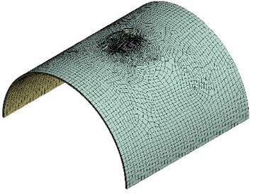
Rockfall impact is mainly composed of two parts: rockfall, coating and pipeline. The three-dimensional model of the pipe and the stone is established. The diameter of the pipe is 1016 mm and the wall thickness is 10 mm. The thickness of fibreglass reinforced epoxy coating and the polyethylene coating are 1.5 mm and 3 mm respectively. The finite element mesh of a typical model is shown in Fig. 1. The spherical rock is 0.1m directly above the pipe and hits the pipe vertically at a speed of 20 m/s. The radius of the rock is 0.05 m. Since the pipeline is very long, symmetric boundary condition are applied on all the boundaries.
Fig. 1Finite element mesh of the rockfall impact problem
Then the structural dynamic equations of the model can be written as:
where , and denote mass matrix, damping matrix and stiffness matrix respectively, , and denote acceleration vector, velocity vector and displacement vector respectively, and is the impact force vector. The finite element equations of Eq. (1) can be solved with proper boundary conditions and initial conditions.
2.2. Elastoplastic constitutive
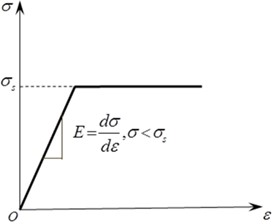
The stress-strain curve of the bilinear ideal elastic-plastic material is shown in Fig. 2, follows the Drucker-Prager yield criterion, which is an approximation of the Mohr-Columb criterion to correct the generalized Mises criterion [9-10].
Fig. 2Stress-strain curve of an ideally elastoplastic material for pipelines
In the finite element model, the falling rock is used as the impact material, and the density is 2000 kg/m3, the elastic modulus is 34 GPa, and the Poisson ratio is 0.23. The pipeline is X70 pipeline steel, and the material constitutive model is bilinear ideal elastic-plastic material with a density of 7850 kg/m3, elastic modulus of 210 GPa, Poisson ratio of 0.3, and yield stress of 520 MPa. The entire finite element model consists of 3493 elements and 3947 nodes.
2.3. Numerical results
For the safety assessment of pipeline under rockfall impact, finite element analysis was performed using the models described in sections 2.1 and 2.2. Fig. 3 give the equivalent stress of the model for pipeline with polyethylene coating at different time, and the time history of equivalent stress of the impact keypoint is given in Fig. 4. Meanwhile the equivalent stress of the model for pipeline with fibreglass reinforced epoxy coating at different time, and the responding time history of equivalent stress of the impact keypoint are given in Fig. 5 and Fig. 6 respectively.
Fig. 3Equivalent stress of the pipeline with polyethylene coating at different time
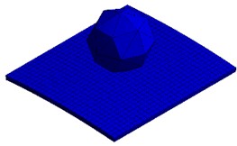
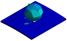
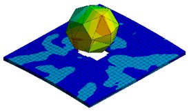
Fig. 4Time history of equivalent stress of the impact keypoint for pipeline with polyethylene coating
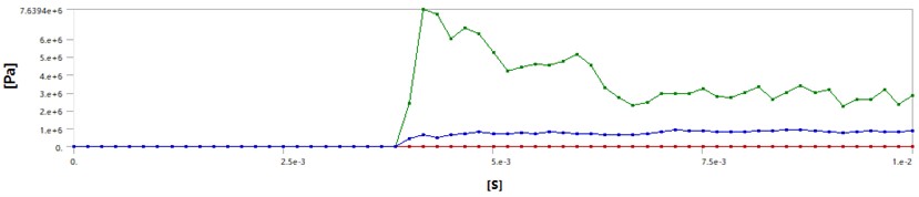
Fig. 5Equivalent stress of the pipeline with fibreglass reinforced epoxy coating at different time
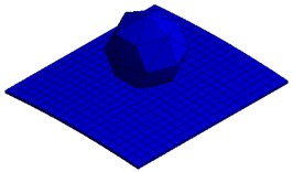
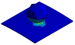
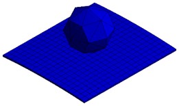
Fig. 6Time history of equivalent stress of the impact keypoint for pipeline with fibreglass reinforced epoxy coating
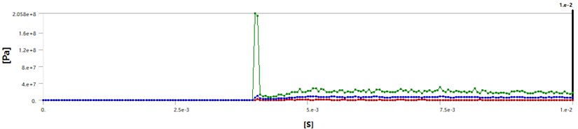
It can be seen that, the impact occurs at about 3.75 ms, since the velocity of the rock is 20 m/s, and the hanging height of the rock is 0.1 m, considering the radius of the rock is 0.05 m, then the impact time should be 3.75 ms, which verifies the correctness of the algorithm. During the computation, the failure criterion is chosen as the maximal Von Mises criterion, and failure stress for polyethylenecoating and fibreglass reinforced epoxycoating are set to be 5 MPa and 500 MPa respectively. It also can be seen from Fig. 3 that, a hole appears at the impact center after impact as the maximal Von Mises stress during the impact is larger than the corresponding failure stress. It is clearly shown in Fig. 5 and Fig. 6 that, since the maximal Von Mises stress during the impact is smaller than the corresponding failure stress, the rock rebounds back.
3. Results and analysis
In this subsection, the effect of rockfall material density and velocity on pipeline safety is studied. The size of rockfall velocity is one of the important factors affecting pipeline safety, and the rockfall velocity is related to the rockfall impact energy. In order to study the influence of rockfall velocity on pipeline safety, other parameters are set the same as in subsection 2.1, and different values of rockfall velocity are taken for numerical simulation. The numerical simulation results are shown in Fig. 7. The values of rockfall velocity are as follows: 11 m/s, 12 m/s, 13 m/s, 14 m/s, 15 m/s, 16 m/s, 17 m/s, 18 m/s, 19 m/s, 20 m/s and 21 m/s. And define the danger factor:
where is the danger factor, is the maximal equivalent stress of the pipeline. Safety factor is taken as 1.25, and yield stress of the material is 520 MPa.
It can be seen from Fig. 7 that under the existing parameter conditions, when the rockfall velocity is equal to 13 m/s, the dangerous value has been reached; When the rockfall velocity is less than 18 m/s, the pipeline risk factor is basically proportional to the rockfall velocity; When the rockfall velocity is greater than or equal to 18 m/s, the peak value of equivalent stress of the pipeline element tends to be stable, and the change amplitude is small, and the stress of the pipeline element gradually reaches the yield limit.
The type of the rock mainly depends on its density, Poisson’s ratio, yield stress and other factors. Kept other parameters the same as before, and this study mainly studies the influence of density. In the finite element model, the falling rock is used as the impact object, and the impact velocity is 20 m/s. The model parameters are set the same as those in Subsection 2.1. The whole finite element model consists of 3493 elements and 3947 nodes. In order to study the effect of rock density on the numerical simulation results of impact process, different values of rockfall density were selected and numerical simulation was carried out. The values of rockfall densities are as follows: 1.4 g/cm3, 1.6 g/cm3, 1.8 g/cm3, 2.0 g/cm3, 2.4 g/cm3, 2.8 g/cm3. The numerical simulation results are shown in Fig. 8.
Fig. 7Variation of danger factor with different rock impact speed
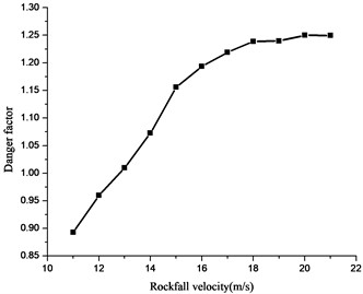
Fig. 8Variation of danger factor with different rock density
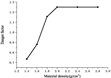
As can be seen from Fig. 8, under the existing parameters, when the rockfall density is less than 1.7 g/cm3, the pipeline is in danger at the beginning; When the rockfall density is less than 2.0 g/cm3, the peak equivalent stress of the pipeline element is positively proportional to the rockfall density, which indicates that the change of rockfall density (i.e., rockfall weight) has a great impact on the deformation of the pipeline, which is mainly because the rockfall weight is directly related to the impact energy of the rockfall. When the falling density is greater than or equal to 2.0, the equivalent stress peak of the pipeline unit is basically unchanged, which is because the maximal stress of the pipeline reaches the yield limit, and the impact energy is about 275 kJ.
Fig. 9Variation of danger factor with different rock radius
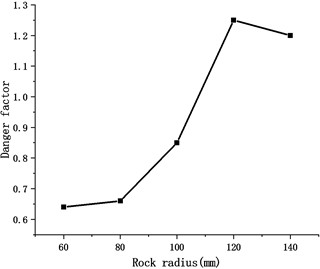
Meanwhile, in order to investigate the effect of radius of the rock, variation of danger factor with different rock radius is shown in Fig. 9. In real circumstances, the shape of the rock could be very sharp and random, in the present investigation, effect of rocks with different radius are computationally investigated. During the computation, the kinetic energy is kept as constant. It can be seen from Fig. 9 that, with the increment of the radius of the rock, the danger factor increases firstly and then decreased. These results revealed that it is very complicated for modeling the impact process with spherical rocks, and the effect of random shape rock should be considered in future investigations.
4. Conclusions
After in-depth finite element analysis, we have gained a more comprehensive understanding of the safety of the pipeline under the impact of falling rocks. The simulation results clearly demonstrate the significant effects of rockfall velocity and material density on the stress distribution and deformation behavior of the pipeline. At lower rockfall velocities, the pipeline can maintain good structural stability. However, with the increment of the impact speed, especially when the impact speed exceeds 13 m/s, the safety condition of the pipeline begins to become less optimistic, as the stress level rises rapidly, close to or even reaching the yield limit of the pipeline material.
Similarly, the density of the rockfall material is also a crucial factor. When the density of falling rock is 2.0 g/cm³ or higher, even if the speed is not very high, the impact energy generated is sufficient high to destroy the pipeline material, thereby increasing the risk of pipeline failure. Therefore, to ensure the safe and stable operation of the pipeline in a complex natural environment, we must give great importance to the impact of rockfall, take targeted protective measures and establish early warning mechanisms. We must respond to possible rockfall events in a timely manner and reduce the threat to pipeline safety.
The present investigation shows clearly the difference between the fibreglass reinforced epoxy and the polyethylene coating, and the numerical method also could be a technical guidance for the protection design and safety maintenance of the pipeline. Future work could be focus on the modeling of effect of random shape rocks.
References
-
H.-J. Li, H.-H. Zhu, C.-X. Zhang, and W. Zhang, “Modelling and analysing failure modes of buried pipelines perpendicularly crossing landslide boundaries,” Soil Dynamics and Earthquake Engineering, Vol. 162, p. 107447, Nov. 2022, https://doi.org/10.1016/j.soildyn.2022.107447
-
A. Yao, T. Xu, Y. Li, and X. Zeng, “Determination of limit load to buried gas pipeline with inner crack under rockfall impact load based on VCCT,” in International Conference on Pipelines and Trenchless Technology, pp. 421–430, Oct. 2011, https://doi.org/10.1061/41202(423)48
-
G. Tavakoli Mehrjardi and M. Karimi, “Numerical modeling of buried steel pipe subjected to impact load,” Journal of Pipeline Systems Engineering and Practice, Vol. 12, No. 4, pp. 1–14, Nov. 2021, https://doi.org/10.1061/(asce)ps.1949-1204.0000588
-
H. F. Jahromi, F. Jafarzadeh, and M. S. Zakaria, “Experimental study of burial depth effect on embedded pipe deformations in sandy slopes under dynamic landsliding,” Soil Dynamics and Earthquake Engineering, Vol. 114, pp. 281–297, Nov. 2018, https://doi.org/10.1016/j.soildyn.2018.06.038
-
Ö. Anil, S. O. Akbaş, O. Gezer, and M. C. Yilmaz, “Investigation of the impact behavior of steel and composite pipes with protective layer,” Structural Concrete, Vol. 18, No. 3, pp. 421–432, Feb. 2017, https://doi.org/10.1002/suco.201600128
-
P. F. Liu, J. Y. Zheng, B. J. Zhang, and P. Shi, “Failure analysis of natural gas buried X65 steel pipeline under deflection load using finite element method,” Materials and Design, Vol. 31, No. 3, pp. 1384–1391, Mar. 2010, https://doi.org/10.1016/j.matdes.2009.08.045
-
F. Dong, X. Bie, J. Tian, X. Xie, and G. Du, “Experimental and numerical study on the strain behavior of buried pipelines subjected to an impact load,” Applied Sciences, Vol. 9, No. 16, p. 3284, Aug. 2019, https://doi.org/10.3390/app9163284
-
P. Rao, Z. Wu, and J. Cui, “Analysis of deformation of adjacent buried pipeline under rockfall impact load,” Geotechnical and Geological Engineering, Vol. 40, No. 3, pp. 1463–1474, Sep. 2021, https://doi.org/10.1007/s10706-021-01975-w
-
K.-J. Bathe, M. D. Snyder, A. P. Cimento, and W. D. Rolph, “On some current procedures and difficulties in finite element analysis of elastic-plastic response,” Computers and Structures, Vol. 12, No. 4, pp. 607–624, Oct. 1980, https://doi.org/10.1016/0045-7949(80)90135-2
-
D. C. Drucker, “Some implications of work hardening and ideal plasticity,” Quarterly of Applied Mathematics, Vol. 7, No. 4, pp. 411–418, Jan. 1950, https://doi.org/10.1090/qam/34210
About this article

The authors have not disclosed any funding.
The datasets generated during and/or analyzed during the current study are available from the corresponding author on reasonable request.
The authors declare that they have no conflict of interest.
