Abstract
The Variable Morphology Wheel-Track Mechanism (VMWTM) is an innovative mobile platform design designed to overcome the limitations of traditional track and wheel designs in different terrains and mission requirements. Based on the importance of the crawler wheel in the tracked vehicle, the vehicle transmission shaft transmits the power and torque of the power source to the crawler chassis, so the overall working performance of the vehicle depends to a certain extent on the performance of the crawler wheel. In-depth and detailed research on the structure of the track wheel module is an important issue in the current vehicle design and manufacturing work. Based on the relevant theories and technologies of the finite element method, this paper conducts in-depth analysis and design. Taking the whole crawler wheel mechanism and the key components as the analysis object, the basic research method is the finite element method. The working principle of the crawler wheel is analyzed, and the load calculation, stress characteristics and structural strength of the key components of the triangular crawler wheel module are deeply explored according to the technical requirements and actual working conditions.
1. Introduction
Its working principle is based on the ability to adaptively change the shape according to the specific situation [1], combining the advantages of track and wheel to provide higher mobility and adaptability [2]. In this paper, the whole crawler wheel and its key components are taken as the analysis object. The basic research method is the finite element method. The working principle of the crawler triangular state is analyzed. The load calculation, force characteristics, structural strength and stiffness of the key components of the triangular crawler wheel module [3] are deeply explored according to the technical requirements and actual working conditions.
2. Basic working principle
2.1. The morphological change mechanism of variability wheel tread
The variability wheel-track device has a mechanism that can change its shape during operation [4]. These mechanisms can be controlled by electric or hydraulic systems to adjust the shape, density or layout of tires or tracks. For example, the rigidity or softness of the tire surface can be adjusted to different states when needed to adapt to different terrains [5].
2.2. The combination of the track of the variable wheel track and the tire
The variable wheel-track device integrates the design of track and tire, and adapts to different usage scenarios by switching or transforming different working modes. On a flat hard ground, a harder tire shape can be used to improve speed and efficiency; on irregular terrain or soft ground, it can be adjusted to wider and softer tires or increase the track surface to enhance traction and stability [6]. The design of variable wheel-track device can also take into account a variety of functional requirements, such as low noise, high bearing capacity, long life, etc., to meet the application requirements of different fields, such as military robots, rescue robots, agricultural machinery, etc. [7].
Through these working principles, the variable wheel-track device can flexibly respond to various complex terrain and mission requirements in practical applications, providing new possibilities and prospects for the design and optimization of mobile platforms.
3. Simulation settings
3.1. Simulation grid settings
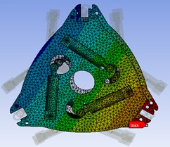
As shown in Fig. 1, enter the Mesh function module.
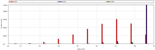
As shown in Fig. 2, Skewness is selected at the Mesh Metric option to view the mesh distortion. The minimum distortion is 1.1689e-005 and the maximum distortion is 0.99998. The average distortion is 0.27835. The number of grids with distortion greater than 0.65 is very small, and the number of grids with distortion less than 0.5 is the majority. The overall mesh distortion is better.
Fig. 1Mesh function module
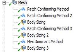
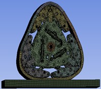
Fig. 2Grid quality histogram
3.2. Simulation of the driver settings
Set the driver as shown in Fig. 3-7.
4. Simulation analysis
4.1. Wheel force analysis
The original structure is shown schematically in Fig. 8, and the structure consists of the following main aspects.
Fig. 3Driving direction diagram
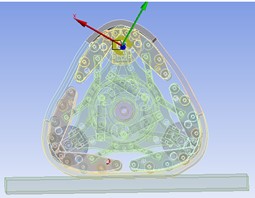
Fig. 4Track driving direction diagram
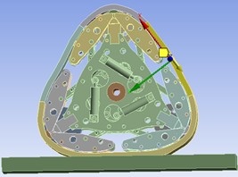
Fig. 5Track driving direction diagram
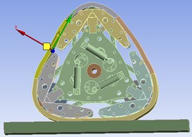
Fig. 6Track drive direction diagram
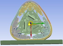
Fig. 7Force direction diagram
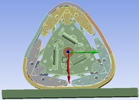
Fig. 8Original structure of track tires
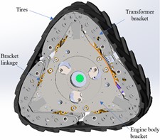
The tire is in a steady state in a circular state, and the downward force is set to 15000 N. The middle part of the track is stationary, and the power assembly, the inner drive plate assembly, the outer drive plate assembly, the inner cage assembly, the outer cage assembly, the guide rod, and the deformed connecting rod [8] are obtained. The overall force situation is shown in Fig. 8. Powertrain force situation as shown in Fig. 8.
As shown in Fig. 10, the minimum and maximum stresses in the static state are 90.663 MPa and 0.00051 MPa, respectively, and the maximum value is lower than the yield limit of the material. As shown in Fig. 11, the stress is mainly concentrated below the wheel. The stress above the wheel is small, and the stress below the wheel is slightly larger. The maximum value appears in the lower right position, and the stress value at the connection between the inner cage assembly and the outer cage assembly is larger, because the connection is not only affected by the lower pressure, but also connected to the inner cage assembly. The outer cage assembly is also stressed, as shown in Fig. 11, and the stress is mainly concentrated below the hole. The force at the connection between the hole and the pin shaft is in good condition, which can ensure the strength of the workpiece connection. In the Figure, the force is mainly concentrated on the middle drive shaft and transmitted downward, plus its own weight, so the force at this position is relatively large.
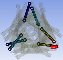
As shown in Fig. 12, the maximum deformation of the structure appears in the lower right corner position, with the maximum deformation value of 2.2655 mm. This position is connected with the inner cage assembly and the outer cage assembly. The force is mainly concentrated under the hole, so the deformation is the largest. The overall deformation is between 0.43869-2.2655 mm, which meets the material properties, so the deformation of the powertrain part meets the requirements.
Fig. 9The overall force of the wheel
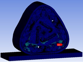
Fig. 10The overall force of the powertrain
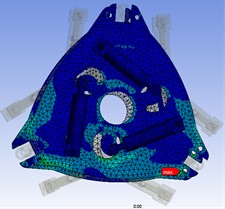
Fig. 11The overall force of the powertrain
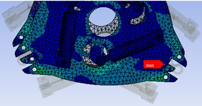
Fig. 12Overall deformation of powertrain
4.2. Stress analysis of deformed connecting rod
As shown in Fig. 13, the deformation connecting rod is connected to the powertrain, the inner cage assembly and the outer cage assembly. The material is 7075-T6. In Fig. 13, it can be seen that the maximum force is 13.718 MPa and the minimum value is 0.05 MPa, which meets the material strength. The force of the deformation connecting rod is consistent with the trend of the stress distribution of the powertrain, and the maximum stress value is distributed in the upper connecting rod. Because it is triangular, the deformation connecting rod is subjected to a small force in the overall force. The material at the connection position in the assembly relationship will not fail due to the action of alternating load.
4.3. Analysis of deformation of deformation connecting rod
As shown in Fig. 14, the maximum deformation of the structure appears at the tire position, and the maximum deformation value is 2.249 mm. This position is the position where the deformed connecting rod connects the powertrain and the inner cage assembly, and the outer cage assembly. The overall deformation is between 0.50952-2.2493 mm, which meets the material properties, so the deformation of the powertrain part meets the requirements.
4.4. Stress analysis of guide rod
As shown in Fig. 15, the force of the guide rod is shown. The guide rod is connected to the powertrain and the inner cage assembly and the outer cage assembly. The material is 707-5T6 (SN). The maximum force is 163.32 MPa and the minimum is 0.018 MPa, which satisfies the material strength. The force of the guide rod is consistent with the trend of the stress distribution of the powertrain, and the maximum stress value is distributed at the connection of the upper bracket. The guide rod is connected to the powertrain and the inner cage assembly and the outer cage assembly, which plays an important role in the transformation action. The material at the connection position of the guide rod in the assembly relationship will not suffer fatigue failure due to the action of alternating load.
Fig. 13Stress of deformed connecting rod
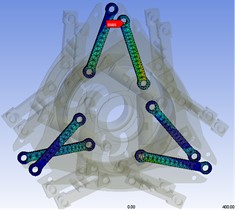
Fig. 14Deformation of deformed connecting rod
4.5. Analysis of guide rod deformation
As shown in Fig. 16, the maximum deformation of the structure appears in the tire position, with the maximum deformation value of 2.2164 mm. The position is that the guide rod is connected with the powertrain and the inner cage assembly and the outer cage assembly. The bearing force above the triangular state is large, so the deformation is the largest. The overall deformation is between 0.17584-2.2168 mm, which meets the material properties, so the deformation of the powertrain part meets the requirements.
Fig. 15Force diagram of guide rod
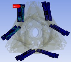
Fig. 16Deformation of guide rod
5. Conclusions
1) The working principle of the triangular track wheel module is analyzed. At the same time, combined with the road conditions of the vehicle equipped with the track wheel, the performance of the vehicle equipped with the track wheel module under normal driving conditions is analyzed.
2) The principle and process of finite element analysis are described in detail. The finite element static analysis of the powertrain and guide rod components is carried out by using ANSYS software. The stress and deformation nephograms under the specified static load conditions are obtained. The maximum stress and the maximum deformation under the static load conditions are pointed out, which provides the technical basis for the lightweight optimization design of the key components of the triangular crawler wheel.
References
-
K. Watanabe and M. Kitano, “Study on steerability of articulated tracked vehicles – Part 1. Theoretical and experimental analysis,” Journal of Terramechanics, Vol. 23, No. 2, pp. 69–83, Jan. 1986, https://doi.org/10.1016/0022-4898(86)90015-7
-
S. Sasaki, T. Yamada, and E. Miyata, “Articulated tracked vehicle with four degrees of freedom,” Journal of Terramechanics, Vol. 28, No. 2-3, pp. 189–199, 1991.
-
Nan Zhang, “Research on track-link compound mobile mechanism,” Beijing Jiaotong University, Beijing, 2014.
-
Mȩżyk A. et al., “Numerical simulation of active track tensioning system for autonomous hybrid vehicle,” Mechanical Systems Signal Processing, 2016.
-
Xiangzheng Meng and L. W. E. Junwen Xing, “Development of multi-functional comprehensive hydraulic and pneumatic experimental device based on integration of teaching-learning-practicing,” Mechanical Engineer, Vol. 2012, No. 11, pp. 16–18, 2012.
-
M. Norouzi, J. V. Miro, and G. Dissanayake, “A statistical approach for uncertain stability analysis of mobile robots,” in IEEE International Conference on Robotics and Automation (ICRA), Vol. 12, pp. 191–196, May 2013, https://doi.org/10.1109/icra.2013.6630575
-
Dongfang Huang, “Current situation, basis and optimization of emergency rescue equipment in my country,” China Emergency Rescue, Vol. 2018, No. 4, pp. 29–32, 2018.
-
W. Park et al., “Prediction of the tractive performance of a flexible tracked vehicle,” Journal of Terramechanics, Vol. 45, No. 1, pp. 13–23, 2008.
About this article

The authors have not disclosed any funding.
The datasets generated during and/or analyzed during the current study are available from the corresponding author on reasonable request.
The authors declare that they have no conflict of interest.
