Abstract
The purpose of the article is an experimental study of the impact of the wheelsets of a mainline diesel locomotive on the railway track on straight sections of the track. The measurements were performed on a vibration measuring device consisting of MV25 DV type sensors and an oscillation converter for a digital signal. It is proved that the indicators of dynamic characteristics comply with regulatory requirements. As a result of the conducted research, digital data was collected from the ADC and general monitoring was carried out. Measurement and signal processing are carried out using special software of a personal computer such as a “Notebook”. Vertical static load of a wheelset of a railway rolling stock unit on rails: the load of a railway rolling stock unit on rails attributed to one wheelset, taking into account the actual location of the center of gravity of the superstructure.
Highlights
- An experimental study of the impact of the wheel sets of the TE33A diesel locomotive on the railway track on straight sections of the track was carried out.
- As a result of the study, the coefficients of vertical dynamics of the first stage of suspension during the movement of the TE33A locomotive on a straight section of the track were determined.
- With the help of computer modeling, stress curves in the inner edge of the sole of the rail are constructed when the TE33A locomotive moves along a straight section of the railway track.
- As a result of the study, it was found that the smooth running performance of the locomotive meets the regulatory requirements when driving at speeds up to structural (120 km/h).
1. Introduction
It is known that the outstanding acceleration is part of the transverse horizontal acceleration of a unit of railway rolling stock acting at the level of the axle box when moving in a circular curve, not compensated by the elevation of the outer rail [1].
Typical design of the upper structure of the track: A structure including a jointless railway track with rails of type R65, reinforced concrete sleepers with a plot from 1,840 to 2,000 pieces per 1 km, crushed stone ballast, or a link railway track with rails of type R65, wooden sleepers with a plot from 1,840 to 2,000 pieces per 1 km, crushed stone ballast [2, 3].
Test (measuring) section of railway track: A section of railway track of limited length intended for conducting complex dynamic (running) and impact tests of rolling stock on the railway track.
The study of dynamic indicators of railway rolling stock is an urgent task for the scientific community. Taking into account the specifics of the railway tracks and the differences in the locomotive fleet, the authors carried out experimental studies using the example of the TE33A diesel locomotive of the Evolution series. The scientific novelty of this study is that for the first time the problems of the impact of the wheel sets of a TE33A series diesel locomotive on a railway track when driving along a straight section of track are considered.
2. Materials and methods
Tests of the locomotive in a straight section were carried out on an odd track of 34 km of the Sorokovaya – Sary-Oba stage. Before the tests, two broken reinforced concrete sleepers were replaced. According to the data of the track measuring car, the condition of the track corresponds to the assessment “good”. The manual measurement data shows that the track width meets the standards [4, 5].
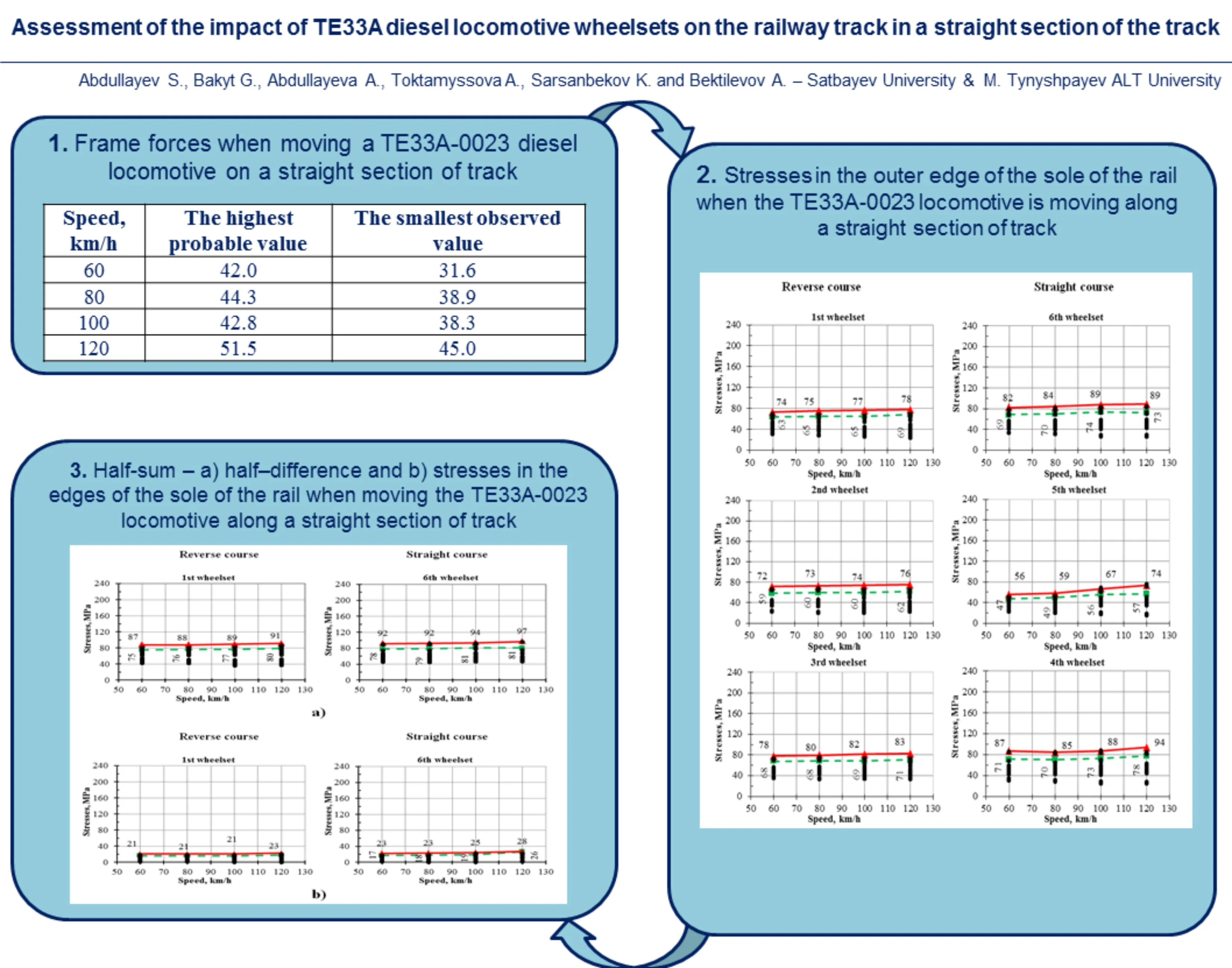
The dynamic performance of the diesel locomotive was measured in the speed range from 60 to 120 km/h. To do this, a diesel locomotive as part of an experimental train consisting of a diesel locomotive and an electric locomotive drove through a section of track equipped with sensors to measure the level of impact on the track at a given speed using the “shuttle” method (Fig. 1 and 2). This study presents the results of experimental investigation of TE33A series diesel locomotive. Fig. 1 and 2 show the results obtained with the help of a mobile vibration measuring complex and with further computer modelling using a personal computer software product of the “Notebook” type. The indicators of frame forces when moving a diesel locomotive on a straight section of track are shown in Table 1.
Table 1Frame forces when moving a TE33A-0023 diesel locomotive on a straight section of track
Speed, km/h | The highest probable value | The smallest observed value |
60 | 42.0 | 31.6 |
80 | 44.3 | 38.9 |
100 | 42.8 | 38.3 |
120 | 51.5 | 45.0 |
Fig. 1The coefficient of vertical dynamics of the first suspension stage when moving a TE33A-0023 locomotive on a straight section of track
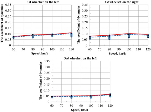
Table 2Coefficients of vertical dynamics of the first suspension stage when moving a TE33A-0023 diesel locomotive on a straight section of track
Speed, km/h | The maximum probable value | Maximum observed value | ||||
1st wheelset | 3rd wheelset | 1st wheelset | 3rd wheelset | |||
On the left | On the right | On the left | On the left | On the right | On the left | |
60 | 0.08 | 0.08 | 0.05 | 0.07 | 0.07 | 0.04 |
80 | 0.09 | 0.09 | 0.05 | 0.09 | 0.08 | 0.05 |
100 | 0.10 | 0.10 | 0.05 | 0.09 | 0.10 | 0.05 |
120 | 0.11 | 0.09 | 0.07 | 0.10 | 0.09 | 0.06 |
The values of the coefficients of vertical dynamics of the TE33A pp diesel locomotive of the railway track are shown in Table 2. The data in Fig. 1-2 and Tables 2-3 show that the dynamic performance of a locomotive in a straight section meets the requirements of acceptable standards [6].
Fig. 2The value of the parameters of the vertical dynamics of the TE33A-0023 diesel locomotive
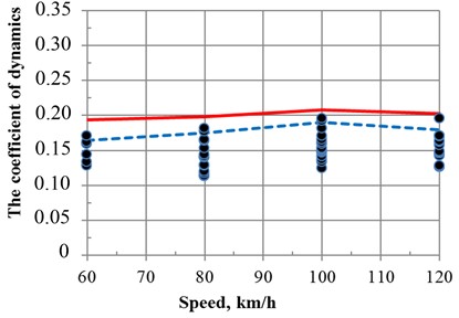
Table 3Coefficient of vertical dynamics of the second suspension stage when moving the TE33A-0023 locomotive on a straight section of track
Speed, km/h | The maximum probable value | Maximum observed value |
60 | 0.19 | 0.16 |
80 | 0.20 | 0.17 |
100 | 0.21 | 0.19 |
120 | 0.20 | 0.18 |
3. Results and discussion
The peculiarity of stress processing in the edges of the sole of the rails is that the data on both rail threads are combined in one row. In this case, the stresses in the outer and inner edges of the sole of the rails are processed separately [7, 8].
Table 4Coefficient of vertical dynamics of the second suspension stage when moving the TE33A-0023 locomotive on a straight section of track
Parameters | Speed, km/h | The wheelset in the course of movement | Maximum | Medium | ||||||
1 | 2 | 3 | 4 | 5 | 6 | |||||
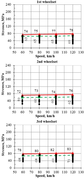
Straight course | Maximum probable | 60 | 74 | 72 | 78 | 75 | 73 | 80 | 80 | 75 |
80 | 75 | 73 | 80 | 79 | 75 | 86 | 86 | 78 | ||
100 | 77 | 74 | 82 | 80 | 74 | 84 | 84 | 79 | ||
120 | 78 | 76 | 83 | 77 | 74 | 82 | 83 | 78 | ||
Medium | 60 | 48 | 43 | 52 | 49 | 43 | 53 | 53 | 48 | |
80 | 48 | 43 | 52 | 48 | 43 | 53 | 53 | 48 | ||
100 | 47 | 42 | 51 | 48 | 43 | 52 | 52 | 47 | ||
120 | 47 | 42 | 52 | 48 | 43 | 51 | 52 | 47 | ||
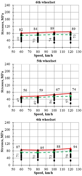
Reverse course | Maximum probable | 60 | 82 | 56 | 87 | 64 | 80 | 64 | 87 | 72 |
80 | 84 | 59 | 85 | 67 | 82 | 67 | 85 | 74 | ||
100 | 89 | 67 | 88 | 80 | 77 | 78 | 89 | 80 | ||
120 | 89 | 74 | 94 | 74 | 90 | 81 | 94 | 84 | ||
Medium | 60 | 52 | 39 | 52 | 45 | 45 | 49 | 52 | 47 | |
80 | 52 | 39 | 52 | 45 | 46 | 50 | 52 | 47 | ||
100 | 53 | 41 | 52 | 50 | 42 | 52 | 53 | 48 | ||
120 | 53 | 42 | 54 | 49 | 46 | 52 | 54 | 49 | ||
The measurement results shown in Fig. 3 and in Table 4 show that the stress level in the edges of the sole of the rail in the straight section under all wheel pairs is almost the same and does not depend on the direction of movement [9]. At the same time, the stress level in the inner edge is slightly higher.
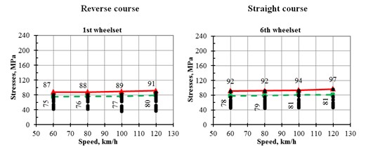
Fig. 3Stresses in the outer edge of the sole of the rail when the TE33A-0023 locomotive is moving along a straight section of track
a) Reverse course
b) Straight course
Fig. 4Half-sum – a) half-difference and b) stresses in the edges of the sole of the rail when moving the TE33A-0023 locomotive along a straight section of track
a)
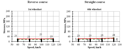
b)
The maximum probable values of the half-sum are in the range from 70 to 100 MPa. The maximum probable values of the half-difference are significantly lower and range from 20 to 30 MPa [10]. Fig. 4 shows the dependence of the half-sum and half-difference of stresses in the edges of the sole of the rail under the first wheelset of the locomotive [11]. The results of calculations of half-sums and half-differences of stresses in the edges of the sole of the rail in the straight section are shown in Table 5.
Evaluating the obtained stress values in the lower edge of the sole of the rails in the straight section of the track, it can be concluded that the achieved level of 111 MPa values is much less than the maximum permissible value of 240 MPa.
Table 5Maximum probable and average values of the stress half-sum in the edges of the sole of the rails in the straight section, MPa
Parameters | Speed, km/h | The wheelset in the course of movement | Maximum | Medium | ||||||
1 | 2 | 3 | 4 | 5 | 6 | |||||
Straight course | Maximum probable | 60 | 87 | 84 | 90 | 89 | 86 | 91 | 91 | 88 |
80 | 88 | 85 | 90 | 90 | 86 | 93 | 93 | 89 | ||
100 | 89 | 86 | 91 | 91 | 85 | 92 | 92 | 89 | ||
120 | 91 | 88 | 93 | 93 | 87 | 92 | 93 | 91 | ||
Medium | 60 | 56 | 50 | 58 | 57 | 51 | 59 | 59 | 55 | |
80 | 56 | 50 | 58 | 56 | 51 | 59 | 59 | 55 | ||
100 | 55 | 49 | 57 | 56 | 49 | 58 | 58 | 54 | ||
120 | 55 | 49 | 57 | 56 | 50 | 57 | 57 | 54 | ||
Reverse course | Maximum probable | 60 | 92 | 67 | 93 | 73 | 93 | 77 | 93 | 83 |
80 | 92 | 67 | 92 | 75 | 93 | 80 | 93 | 83 | ||
100 | 94 | 75 | 93 | 83 | 86 | 88 | 94 | 87 | ||
120 | 97 | 78 | 99 | 83 | 95 | 89 | 99 | 90 | ||
Medium | 60 | 59 | 47 | 58 | 52 | 53 | 55 | 59 | 54 | |
80 | 60 | 46 | 58 | 52 | 53 | 56 | 60 | 54 | ||
100 | 60 | 48 | 57 | 56 | 48 | 57 | 60 | 55 | ||
120 | 60 | 49 | 59 | 56 | 52 | 57 | 60 | 55 | ||
The results of measurements of the lateral forces transmitted from the wheelset guide to the rail are shown in Fig. 5. The level of lateral forces is almost the same for all locomotive wheelsets, does not depend on the speed and direction of movement and the maximum probable value does not exceed 17 kN [12].
Fig. 5Lateral forces from the wheel to the rail when moving the TE33A-0023 diesel locomotive along a straight section of track
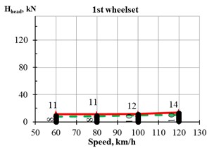
a) Reverse course
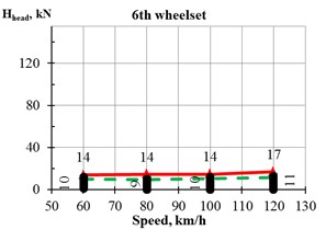
b) Straight course
The vertical forces from the wheel to the rail increase slightly with increasing speed, and when moving from 60 to 120 km/h, this increase is 18 %. This indicates that in straight sections over the entire range of speeds of the locomotive in the vertical plane, the path has a slight dynamic effect. The level of these forces under all wheel pairs of the locomotive is almost the same [13, 14].
4. Conclusions
As a result of the conducted research, the following conclusions were obtained:
1) The dynamic linear load on the track from the trolley on the straight section of the track and on the switches meets the requirements of the established standards.
2 The stresses on the main site of the roadbed, in the ballast under the sleeper, on the upper bed of wooden sleepers for crumpling under the lining are within acceptable limits.
3) The indicators of the smooth running of the locomotive comply with regulatory requirements when moving at speeds up to structural.
Thus, the compliance of the results of the dynamic study with all regulatory requirements will allow to maintain and further improve the safety indicators in the process of operation of the diesel locomotives under consideration.
References
-
C. Wan, V. L. Markine, and I. Y. Shevtsov, “Improvement of vehicle-turnout interaction by optimising the shape of crossing nose,” Vehicle System Dynamics, Vol. 52, No. 11, pp. 1517–1540, Nov. 2014, https://doi.org/10.1080/00423114.2014.944870
-
G. Rill and M. Schuderer, “A second-order dynamic friction model compared to commercial stick-slip models,” Modelling, Vol. 4, No. 3, pp. 366–381, Aug. 2023, https://doi.org/10.3390/modelling4030021
-
S. Abdullayev, G. Bakyt, A. Kamzina, N. Suleyeva, and N. Tokmurzina-Kobernyak, “Dynamic interaction of the TE-33A diesel locomotive and the track in a curve with a radius of 600 meters,” International Journal of Mechanical Engineering and Robotics Research, Vol. 13, No. 2, pp. 205–212, Jan. 2024, https://doi.org/10.18178/ijmerr.13.2.205-212
-
A. Lau and I. Hoff, “Simulation of train-turnout coupled dynamics using a multibody simulation software,” Modelling and Simulation in Engineering, Vol. 2018, pp. 1–10, Jul. 2018, https://doi.org/10.1155/2018/8578272
-
A. Johansson et al., “Simulation of wheel-rail contact and damage in switches and crossings,” Wear, Vol. 271, pp. 472–481, 2011.
-
M. O. Mussabekov, G. B. Bakyt, A. M. Omirbek, E. Brumerčíková, and B. Buková, “Shunting locomotives fuel and power resources decrease,” in MATEC Web of Conferences, Vol. 134, p. 00041, Nov. 2017, https://doi.org/10.1051/matecconf/201713400041
-
E. Di Gialleonardo, S. Bruni, and H. True, “Analysis of the nonlinear dynamics of a 2-axle freight wagon in curves,” Vehicle System Dynamics, Vol. 52, pp. 125–141, 2014.
-
E. Pennestrì, V. Rossi, P. Salvini, and P. P. Valentini, “Review and comparison of dry friction force models,” Nonlinear Dynamics, Vol. 83, No. 4, pp. 1785–1801, Nov. 2015, https://doi.org/10.1007/s11071-015-2485-3
-
S. Bruni, J. Vinolas, M. Berg, O. Polach, and S. Stichel, “Modelling of suspension components in a rail vehicle dynamics context,” Vehicle System Dynamics, Vol. 49, No. 7, pp. 1021–1072, Jul. 2011, https://doi.org/10.1080/00423114.2011.586430
-
P. Olejnik and S. Ayankoso, “Friction modelling and the use of a physics-informed neural network for estimating frictional torque characteristics,” Meccanica, Vol. 58, pp. 1–24, Oct. 2023, https://doi.org/10.1007/s11012-023-01716-8
-
S. Abdullayev, N. Tokmurzina-Kobernyak, G. Ashirbayev, G. Bakyt, and A. Izbairova, “Simulation of spring-friction set of freight car truck, taking into account track profile,” International Journal of Innovative Research and Scientific Studies, Vol. 7, No. 2, pp. 755–763, Mar. 2024, https://doi.org/10.53894/ijirss.v7i2.2883
-
P. M. Jawahar, K. N. Gupta, and E. Raghu, “Mathematical modelling for lateral dynamic simulation of a railway vehicle with conventional and unconventional wheelset,” Mathematical and Computer Modelling, Vol. 14, pp. 989–994, Jan. 1990, https://doi.org/10.1016/0895-7177(90)90326-i
-
M. R. Ghazavi and M. Taki, “Dynamic simulations of the freight three-piece bogie motion in curve,” Vehicle System Dynamics, Vol. 46, No. 10, pp. 955–973, Oct. 2008, https://doi.org/10.1080/00423110701730737
-
M. M. Azilkiyasheva, S. B. Shayakhmetov, G. B. Bakyt, B. T. Kopenov, Y. Y. Baubekov, and A. Zhauyt, “Development of a method for calculating the degree of use of the plasticity resource (Dupr) when rolling on a new continuous mill,” Metalurgija, Vol. 60, No. 3-4, pp. 362–364, 2021.
About this article

The authors express their gratitude to the leaderships of Satbayev University and ALT University for the opportunity to perform this research.
The datasets generated during and/or analyzed during the current study are available from the corresponding author on reasonable request.
The authors declare that they have no conflict of interest.
