Abstract
During loading and driving, the wheels bear the vertical load from the body mass and the excitation load generated by uneven road surface on the one hand, and bear the driving torque on the other hand. The load-bearing methods of wheels are generally divided into bottom load-bearing and top load-bearing. This paper describes the structural characteristics of the track system of the articulated track vehicle and the interaction relationship between the main components of the track system. Finite element calculation is carried out based on ANSYS software to obtain the stress distribution of each key component under various loading methods. It can be seen from the results that all key components of the track system can meet the strength and rigidity requirements; although there are also areas with large local stress, they are all within the safe range, which is mainly caused by stress concentration. Safe life is obtained through fatigue analysis.
1. Introduction
Traditional rigid wheels, such as solid tires, rail wheels, etc., all belong to the bottom-bearing method. When the wheel carried on the bottom rotates, only the part that directly contacts the ground is responsible for bearing the vertical load, while the other parts are not subjected to force [1-2]. Although the wheel in this load-bearing method has a strong load-bearing capacity, it has poor vibration damping performance, poor comfort, and the load-bearing capacity per unit mass of the wheel is low, so it is generally only used for special vehicles built in special environments. Pneumatic wheels and most non-pneumatic wheels are top-loaded [3]. Taking a crawler wheel as an example, when a top-loaded wheel is loaded on a truck, the cage assembly at the lower end of the wheel bends freely due to extrusion and deformation, while the cage assembly at the upper end of the wheel bears the tension from the suspension hub. When the wheel is running, as the cage assembly deforms, the cage assembly will rotate in a plane around the rotating shaft. When the cage assembly is subjected to pressure, the cage assembly will bend freely due to rotation, so it will not bear the vertical load from the axle [4]; when the cage assembly is subjected to tensile force, the cage assembly will be in tension. state, bearing the vertical load from the axle and playing a force transfer role
2. Working principle analysis
When the wheel is actually loaded and loaded, the powertrain transfers the vertical load to the cage assembly, guide rods and deformed links through the suspension hub. If only the straight-line driving condition is considered, that is, the wheel is not subjected to lateral forces [5], then the force situation of the wheel at this time can be simplified to a two-dimensional plane mechanical model for analysis [6].
The original structure is shown schematically in Fig. 1, and the structure consists of the following main aspects.
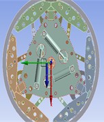
The driver settings are shown in Figs. 2-4.
The tire is in a steady state in a circular state. Set the downward force to 15000 N, the tire speed to 80 km/h, and the simulation setting time of 0.1 s to obtain the force conditions of the powertrain, inner drive plate assembly, outer cage assembly, guide rod, and deformation link [7].
Fig. 1Schematic diagram of the original structure
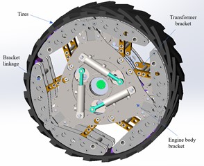
Fig. 2Schematic diagram of rotation direction
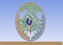
Fig. 3Schematic diagram of speed direction
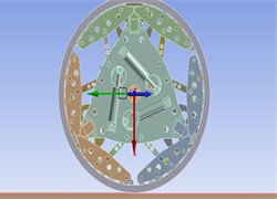
Fig. 4Schematic diagram of force direction
3. Simulation analysis of tracked wheel
Through the simulation analysis of the given boundary conditions, the stress change diagram of the circular track theory is obtained by rotating for one revolution, as shown in Fig. 5, starting from the starting position, a total of four segments are intercepted as a reference, reflecting the different motion conditions.
The variation of the rotational stress curve of the tracked wheel is shown in Fig. 6.
Fig. 5Changes during rotation of track wheels
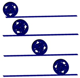
Fig. 6Stress variation during wheel rotation
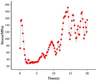
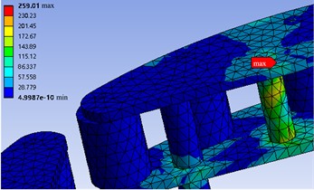
It can be seen from Fig. 6, when the track starts accelerating from the stationary state, due to the sudden increase in speed, so it leads to an instantaneous increase in stress, and the growth rate is faster, when the wheel begins to rotate, the value of stress begins to decrease, and as the speed continues to increase, the value of stress increases, when the time reaches 5 s, the value of stress presents a positive cyclic fluctuation trend and tends to grow steadily. Fig. 7 shows a nephogram of the stress exerted on the entire wheel.
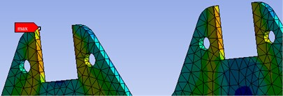
As shown in Fig. 7, the minimum and maximum values of the stress under the transient state are 0.045 MPa and 259.01 MPa respectively, and the maximum value is lower than the yield limit of the material. As shown in Fig.8, the stress is mainly concentrated in the three sharp corners, which shows that the stress in the center of the wheel is small and the stress at the sharp corners is slightly higher. The maximum value appears in the upper position, and the stress values at the connection with the inner cage assembly and the outer cage assembly are large, because the connection is not only affected by downward pressure. In addition, the inner cage assembly and the outer cage assembly connected are also stressed. As shown in Fig. 8, the force is mainly concentrated below the hole. The force at the connection between the hole and the pin shaft is in good condition, which can ensure the strength of the workpiece when connected. In the Figure, the force is mainly concentrated on the middle transmission shaft and transmitted downward, plus its own weight, so the force at this position is relatively large. The materials placed at the connected locations in the assembly relationship will not experience fatigue failure due to alternating loads.
Fig. 7Overall wheel stress nephogram
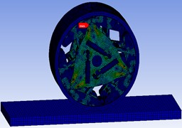
Fig. 8Overall stress situation of powertrain
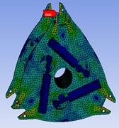
Fig. 9The local stress situation at the lower end
4. Life and safety factor analysis
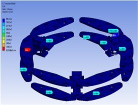
It can be seen from Fig. 10 that the minimum safety factor [10] of the powertrain components is 1.3964, which appears in the connection plate mounting holes in the connection areas of the powertrain with the inner cage assembly and the outer cage assembly. The safety factors of the areas where the rest of the mounting holes are located are 4.2623 and 6.1187 respectively, which meet the design requirements for fatigue safety factors. The safety factor range for non-hole and groove areas of the connection plate is between 2.4699 and 15; The overall safety factor in the powertrain area is greater than 1, which meets the fatigue safety factor requirements and meets the basic requirements of the expected fatigue life goal.
Combined with the movement requirements of the track wheels, it can be seen that the speed of 80 km/h of the track wheels is 38.314 rad/s. It can be seen that under uniform speed, the time it takes for the powertrain to rotate for one week is 0.1496 s. As shown in Fig. 6, combined with the fatigue life cycle number of 1e6, the total life of the powertrain can be obtained as (1e6 ×0.1496)/60×60 = 41.55 h, and the overall structural life of the powertrain is 1e6 times.
It can be seen from Fig. 10 that the minimum safety factor of the inner cage assembly component is 0.67372, which appears on the surface of the connecting shaft in the connection area between the inner cage component and the guide unit. The safety factor of this part is less than 1 and does not meet the safety standard. Therefore, fatigue fracture will occur during the running cycle of the track wheel, which will affect the overall safety performance of the track wheel; The safety factor of the area where the inner cage assembly is located is concentrated in the range of 2.2211 to 15 to meet the design requirements of fatigue safety factor; it can be seen from Fig. 8 that the overall safety factor of the guide unit is concentrated between 5.981 and 15.0, which are both greater than 1 to meet the fatigue safety factor requirements and meet the basic requirements of the expected goal of fatigue life.
Fig. 10Powertrain safety factor and fatigue life diagram
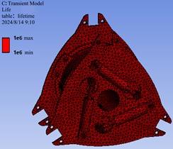
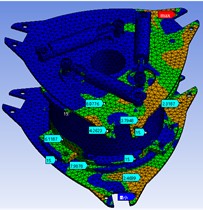
Fig. 11Inner cage assembly, outer cage assembly
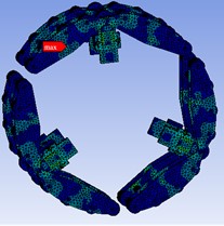
Fig. 12Maximum values of inner cage assembly and outer cage assembly
As shown in Fig. 11, the wheel drive assembly is stressed. The inner cage assembly and the outer cage assembly are in contact with the tire and play an important role in the main body. The inner cage assembly and the outer cage assembly are composed of a guide unit, a cage, and a guide wheel. The guide unit material is steel, the guide wheel material is nylon, and the cage material is 7075-T6. It can be seen in Fig. 12 that the maximum stress value is 259.01 MPa. The minimum value is 0.0004 MPa, and the maximum value appears at the guide unit, which meets the material strength. The stress distribution trend of the inner cage assembly and outer cage assembly is consistent with the stress distribution rule of the power assembly. Due to the rotating motion and the maximum stress value is distributed in the position of the bracket link, because the motion link plays a supporting role, the inner cage assembly and outer cage assembly wheel drive assembly are connected to the tire, which is the main supporting part in the government. It plays a supporting role in a circular state, and the materials placed at the connection positions of the inner cage assembly and the outer cage assembly in the assembly relationship will not experience fatigue failure due to alternating loads.
Combined with the movement requirements of the track wheels, it can be seen that the speed of 80 km/h of the track wheels is 38.314 rad/s. It can be seen that at a uniform speed, the time it takes for the powertrain to rotate for one week is 0.1496 s. As shown in Fig. 12, the minimum life of the inner cage assembly components occurs in the guide unit area. The number of fatigue cycles in this part is only 1.315e5, and the total life is 5.465 h; Except for the guide unit, the fatigue life cycles of the inner cage assembly components are all 1e6, and the total life of the powertrain can be obtained as (1e6 ×0.1496)/60×60 = 41.55 h.
Fig. 13Safety factor for inner cage assembly components
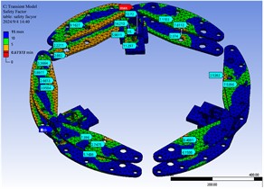
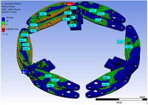
Fig. 14Safety factor of guide unit
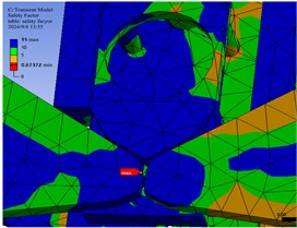
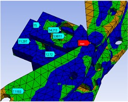
Fig. 15Fatigue life of inner cage assembly components
It can be seen from Fig. 13 that the minimum safety factor of the outer cage assembly components is 0.60235, which appears on the surface of the connecting shaft in the connection area between the outer cage components and the guide unit. The safety factor of this part is less than 1 and does not meet the safety standard. Therefore, fatigue fractures will occur during the running cycle of the track wheel, which will affect the overall safety performance of the track wheel; As shown in Fig. 14, the safety factor of the connecting plate in the area where the outer cage assembly is located is concentrated in the range of 2.2211 to 15 to meet the design requirements for fatigue safety factor, and the safety factor range of the outer cage assembly components is between 2.0237 and 15; It can be seen from Fig. 15 that the overall safety factor of the guide unit is concentrated between 5.981 and 15, which are both greater than 1 to meet the fatigue safety factor requirements and meet the basic requirements of the expected fatigue life goal.
5. Conclusions
1) This paper introduces the development history and development trend of the structure shape of the track wheel, explains the basic kinematic characteristics, and proposes a rational plan for this design that can use finite element simulation analysis to optimize the structure shape.
2) Based on the technical requirements of the track wheel module and combined with the actual situation of the vehicle equipped with track wheels, the stress and life simulation are carried out on the initial design and assembly of the round track wheel to obtain the fatigue strength, and the strength optimization design is carried out on key components.
3) Using ANSYS software to conduct finite element static analysis on the powertrain, inner and outer cage assemblies, obtain stress nephograms under the specified static load conditions, and point out the position of the maximum stress under the static load conditions, Provide reference basis for subsequent lightweight design.
References
-
K. Watanabe and M. Kitano, “Study on steerability of articulated tracked vehicles – Part 1. Theoretical and experimental analysis,” Journal of Terramechanics, Vol. 23, No. 2, pp. 69–83, Jan. 1986, https://doi.org/10.1016/0022-4898(86)90015-7
-
K. Watanabe, K. Sawagashira, and M. Kitano, “Study an the steerability of articulated tracked vehicles,” Journal of Terramechanics, Vol. 21, No. 3, pp. 305–305, 1984.
-
Hongnan Xu, “Development and market prospect analysis of rubber tracked all-terrain vehicle,” Special Purpose Vehicle, Vol. 3, 1996.
-
K. Huh, B. H. Cho, and J. H. Choi, “Development of a track tension monitoring system in tracked vehicles,” Proceedings of the Institution of Mechanical Engineers Part D Journal of Automobile Engineering, Vol. 215, No. 5, pp. 567–578, 2010.
-
S. Sasaki, T. Yamada, and E. Miyata, “Articulated tracked vehicle with four degrees of freedom,” Journal of Terramechanics, Vol. 28, No. 2-3, pp. 189–199, 1991.
-
S. Miao, “Dynamic simulation and finite element analysis of the walking system of articulated tracked vehicle,” Jilin University, 2018.
-
J. Edlund, E. Keramati, and M. Servin, “A long-tracked bogie design for forestry machines on soft and rough terrain,” Journal of Terramechanics, Vol. 50, No. 2, pp. 73–83, 2013.
-
C. Dong et al., “Pitching movement performance of all terrain articulated tracked vehicles,” Journal of Jilin University, Vol. 47, No. 3, pp. 827–836, 2017.
-
K. Dong, Vehicle Handling Mechanics. Changchun: Jilin Science and Technology Publishing House, 2009.
-
M. Norouzi, J. V. Miro, and G. Dissanayake, “Probabilistic stable motion planning with stability uncertainty for articulated vehicles on challenging terrains,” Autonomous Robots, Vol. 40, No. 2, pp. 1–21, 2016.
About this article

The authors have not disclosed any funding.
The datasets generated during and/or analyzed during the current study are available from the corresponding author on reasonable request.
The authors declare that they have no conflict of interest.
