Abstract
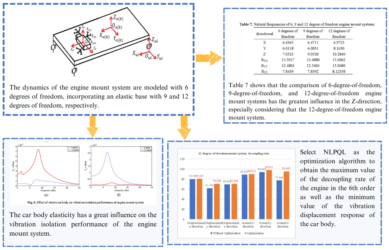
The multi-degree-of-freedom engine mount system presents a coupling issue that significantly impacting its vibration isolation performance. Although the optimization theories for decoupling 6-degree-of-freedom (6-DOF) and 12-degree-of-freedom (12-DOF) engine mount systems are relatively well-developed, previous studies have predominantly focused on engine response and often overlook the impact of car body vibrations. To address this gap, this article conducts an in-depth investigation into how the elasticity of the car body affects the vibration isolation performance of the engine mount system. Initially, the dynamics of the engine mount system are modeled with 6 degrees of freedom, incorporating an elastic base with 9 and 12 degrees of freedom, respectively. The study then analyzes how body elasticity influences the natural frequencies and modal shapes of the engine mount system. Subsequently, the sensitivity of the engine mount system is assessed using Isight analysis to evaluate the three directional stiffnesses of the mount. Finally, the decoupling optimization of the 12-degree-of-freedom engine mount system is performed using the NLPQL (Sequential Quadratic Programming) method. The findings indicate that: (1) considering the car body’s influence directly affects the natural characteristics and decoupling efficiency of the engine mount system; (2) body elasticity in the Z-direction has the greatest impact on the system’s vertical natural frequency; and (3) the NLPQL method effectively enhances the decoupling rate of the engine mount system.
Highlights
- considering theThe paperconsidering the car body’s influence directly affects the natural characteristics and decoupling efficiency of the engine mount system.
- The body elasticity in the Z-direction has the greatest impact on the system’s vertical natural frequency.
- The NLPQL method effectively enhances the decoupling rate of the engine mount system.
1. Introduction
The engine mount system serves as a critical vibration isolation element between the engine and the vehicle body, and its performance significantly impacts the vehicle’s noise, vibration, and harshness (NVH) characteristics [1]. Historically, studies on engine mount system coupling have been based on the assumption of a six-degree-of-freedom engine mount system with its lower attachment point connected directly to a rigid foundation [2]. However, with the trend towards lightweight automotive designs, this assumption has proven to be inherently limiting. There is a growing need to develop more accurate models of engine mounting systems that account for an elastic base.
In designing a powertrain engine mount system, achieving full decoupling under excitation is desired. The system is often subjected to specific excitations with a single frequency, treated as a pure response system. Decoupling the powertrain engine mount system is crucial for enhancing vibration isolation performance. This involves selecting appropriate parameters, such as the position, mounting angle, stiffness, and damping characteristics of each engine mount, and ensuring proper matching of natural frequencies.
Consequently, significant research has focused on decoupling and optimizing the design of powertrain engine mount systems, particularly rubber engine mounts. Jeong and Singh [3] introduced a torque axis (TRA) decoupling condition for an undamped rubber engine mount system and verified this condition. Courteille [4] conducted a multi-objective robust optimization of a powertrain engine mount system using a Pareto-based genetic algorithm. Park and Singh [5] extended the TRA decoupling theory by addressing powertrain rubber engine mounts with proportional and non-proportional damping. They further explored the frequency-varying characteristics of hydraulic engine mounts and developed analytical models using transfer functions and mechanical modeling methods [6]. Liette [7] advanced this by extending the decoupling theory to a 24-degree-of-freedom model to account for coupled powertrain and frame effects. Tan [8] proposed a comprehensive vehicle model to optimize parameters for isolating vibrations transmitted from the powertrain to the chassis. Angrosch [9] demonstrated the effectiveness of implementing two decoupling concepts in multi-body system dynamics simulation and optimized engine mount system design based on torque axis decoupling. Ooi [10] focused on optimizing engine mount system design by considering the dynamic stiffness and damping of rubber mounts to improve model accuracy. Zhou [11] outlined a methodology for engine mount system design, including vibration decoupling, simulation analysis, and topology optimization, demonstrating its feasibility through experiments. Truong N H [12] and colleagues developed hybrid algorithms (HNSGA-III and MOPSO) combining particle swarm optimization with genetic algorithms for engine mount system optimization. Cai [13] employed Chebyshev polynomials and the vertex method to analyze and optimize the system’s natural characteristics. Lü [14] proposed a new reliability analysis method incorporating correlation and interval variables to assess the impact of uncertain information on system output. Wu [15] decoupled and optimized a 12-degree-of-freedom engine mount system using Isight and MATLAB, based on Hu’s [16] theory of complete decoupling of the elastic base torque axis. Additionally, Lee [17] investigated whether car body elasticity should be considered in engine mount system decoupling for comparative analysis.
Analytical studies on the coupling characteristics of engine mounts that consider elastic bases are limited. Most existing research focuses on the differences in natural frequencies between engine mount systems with 6 degrees of freedom (6-DOF) and those with 9 or 13 degrees of freedom. In this paper, we derive the dynamic models for engine mount systems with 6, 9, and 12 degrees of freedom, including cases with a rigid base and an elastic base at the lower attachment point of the engine mount. The natural frequencies for these models are computed using parameters provided by an original equipment manufacturer. First, we compare the natural frequencies of a 9-degree-of-freedom engine mount system with the lower attachment point connected to a rigid versus an elastic foundation. The comparison reveals that the most significant differences in natural frequencies are observed in the vertical direction. When comparing with the 12-degree-of-freedom engine mount system with an elastic base, significant changes are noted across all six directions. Next, we compare the 6-degree-of-freedom engine mount system with a rigid base to the 12-degree-of-freedom engine mount system with an elastic base, analyzing each mode of vibration. The study also examines how varying the three-point engine mount stiffness by factors of 0.1, 0.5, 1, 2, 5, and 10 affects the natural frequency of the engine mount system, highlighting the sensitivity of the natural frequencies to changes in stiffness in different directions. Finally, we apply the NLPQL algorithm for multi-objective optimization, using the stiffness and mounting position of the engine mount as design variables. The optimization aims to maximize the decoupling rate for each vibration mode and minimize the displacement response of the vehicle’s center of mass. The numerical results demonstrate that, when considering body coupling, the proposed optimization method effectively addresses the engine mount system coupling problem and significantly improves the decoupling rate across different vibration modes.
2. Modeling of engine mount system
The generalized coordinates of the fuel-fired four-cylinder engine are denoted as qe(t)=[xpypzpθpxθpyθpz], where xp, yp, and zp represent the engine’s translational movements along the three coordinate axes, and θpx, θpy, and θpz denote the rotational movements around these axes. The 6-degree-of-freedom (6-DOF) engine mounting system is illustrated in Fig. 1.
Fig. 16-degree-of-freedom engine mount system
The stiffness Kmi and damping Cmi of the ith engine mount element in local coordinates are shown in Eq. (1):
The local engine mount stiffness matrix Kmi and damping matrix Cmi are transformed into the engine coordinates Op-Xp-Yp-Zp using the rotation matrix T. In these engine coordinates, the stiffness matrix and damping matrix are represented as shown in Eq. (2):
The rotation matrix T is shown in Eq. (3):
Therefore, the ith engine mount element translational displacement of see Eq. (4):
uie=[xieyiezie]T is the position of the ith engine mount element relative to the center of mass of the four-cylinder engine.
Then Eq. (4) can be rewritten as Eq. (5):
The equation, trp=[xpypzp], tθp=[θxpθypθzp].
Using the diagonal matrix method to represent the second term of the right-hand side of the Eq. (5) by cross-multiplication, Eq. (5) can be expressed as Eq. (6):
where, the matrix Aiesee Eq. (7):
Solve for the displacement qie(t) of the ith engine mount element according to Eqs. (5-7) See Eq. (8):
where, Pie is shown in Eq. (9):
Based on the above derivation the force fie(t) and moment Tie(t) acting on the engine for the ith engine mount can be obtained as:
Combining Eqs. (10-11) yields the final vibration differential Eq. (12) for the six-degree-of-freedom engine mount system:
where, the mass matrix Me, the stiffness matrix Ke, and the damping matrix Ce see Eqs. (13-14):
where, me and Iexx, Ieyy, Iezz, Iexy, Iexz, Ieyz denote the mass and the corresponding inertia of the engine, respectively.
2.1. 12-degree-of-freedom and 9-degree-of-freedom engine mount systems
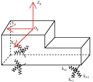
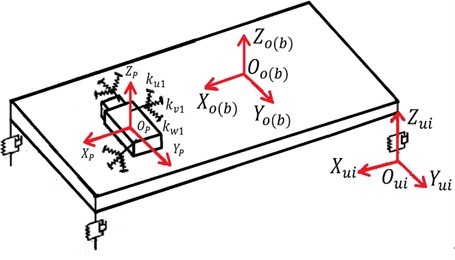
The 12-degree-of-freedom engine mount system, comprising a rigid car body and four bushings, is illustrated in Fig. 2. The body coordinates for the 12-degree-of-freedom system are denoted as qc(t)=[xb,yb,zb,θxb,θyb,θzb], where xb, yb, and zb represent the translational movements of the car body along the coordinate axes, and θxb, θyb, and θzb denote its rotational movements around these axes. The displacement of the i-th engine mount element relative to the car body is given by uic=[xic,yic,zic]. The displacement of the ith engine mount element with respect to the car body is described by qic(t), as given in Eq. (15):
where, Pic is denoted see Eq. (16):
Fig. 212-degree-of-freedom engine mount system
The forces fie(t), fic(t) acting on the four-cylinder engine and the car body by the ith engine mount element can be solved in conjunction with Fig. 2 see Eqs. (17-18):
The moments Tie(t), Tic(t) of the ith engine mount acting on the four-cylinder engine and the car body are shown in Eqs. (19-20):
The forces and moments fkc(t), Tkc(t) acting on the car body by the kth bushing are given in Eqs. (21-22):
where the matrix Aie is the same as Eq. (7), and the skew-symmetric matrices Aic, Akc and the matrix Pkc are represented as follows in Eqs. (23-25):
where xkc, ykc, zkc is the position of the kth bushing element in the car body center of mass coordinates. Therefore, the stiffness and damping matrices kc, cc of individual bushings in their respective local coordinates are shown in Eq. (26):
The stiffness matrix Kkc and damping matrix Ckc for the kth bushing in body coordinates are shown in Eq. (27):
The stiffness matrix and damping matrix of the car body consisting of 4 bushings are shown in Eq. (28):
Therefore, the vibration differential equation for the 12-degree-of-freedom engine mount system is Eq. (29):
where, M is the mass matrix of the engine mount system of the 12-degree-of-freedom engine, C is the damping matrix, K is the stiffness matrix, and f(t) is the input excitation. Where, the matrices M, K, C, see Eqs. (30-34):
where, Ke→c, Cc→e, Kc→e, Ce→c are the coupling stiffness matrix and damping matrix between the engine and the car body, fe(t), fc(t) are the engine excitation and road excitation, and Mc is the car body mass matrix.
When only nine degrees of freedom are considered, only the X and Y directions and the vertical direction of the car body are considered in the engine mount system. In this case, the matrices Pic and Pikc of the 12-degree-of-freedom-based engine mount system are:
2.2. Natural frequencies and decoupling rates for 6-degree-of-freedom, 9-degree-of-freedom, and 12-degree-of-freedom engine mount systems
The differential equations for the dynamics of the 6-degree-of-freedom, 9-degree-of-freedom, and 12-degree-of-freedom engine mount systems are treated as undamped forms, see Eqs. (36-37):
Set the solution of Eq. (36-37) as X(e)=A(e)ejωt, then the main vibration pattern A of the 6-degree-of-freedom, 9-degree-of-freedom, and 12-degree-of-freedom engine mount systems is obtained from Eq. (38):
To verify the accuracy of Eqs. (1-38), the authors validate the mathematical modes of the 9 degrees of freedom mount system. Combining Eqs. (1-38), the data from the Shangguan [18] article are cited to obtain the values of the intrinsic frequency for the first six orders of the 9 degrees of freedom mount system. Details are shown in Table 1.
Table 1Natural frequencies of 9-degree-of-freedom engine mount system
Directional | 9 degree of freedom | 9 degree of freedom [18] |
X | 7.39 | 7.41 |
Y | 7.17 | 7.24 |
Z | 10.48 | 10.50 |
RXX | 16.39 | 16.47 |
Ryy | 10.26 | 10.37 |
Rzz | 12.23 | 12.30 |
As can be seen from Table 1, the difference between the intrinsic frequency of the 9-degree-of-freedom mount system obtained by the mathematical formulation derived in the article and that obtained by the Shangguan [18] article is very small. Therefore, the accuracy of the mathematical formulas derived in this paper is verified.
The energy approach is used to solve for the energy occupied by each order of the engine mount system, corresponding to the decoupling rate of the engine mount system. The parameters about the engine mount system are shown in Tables 2 to 6.
Table 2Engine and car body related mass and inertia parameters
Me (kg) | Ixx (kg.m2) | Iyy (kg.m2) | Izz (kg.m2) | Ixz (kg.m2) | Ixy (kg.m2) | Iyz (kg.m2) | |
Engine | 168.8 | 14.036 | 5.8191 | 10.579 | 0.428 | 0.394 | 0.155 |
Car body | 892.2 | 264.7 | 1658.5 | 2219 | –253.2 | 235 | 226.4 |
Table 3Engine center of mass, car body center of mass and position of each engine mount in car coordinates (unit: mm)
Coordinate | Engine center of gravity | Car body center of gravity | Left engine mount | Right engine mount | Rear engine mount |
X | 1400 | 0 | 1090.1 | 1983.4 | 272.4 |
Y | -20 | 0 | –150.2 | –72.7 | 337.6 |
Z | 140 | 0 | 355.8 | 174.1 | –114.1 |
Table 4Mounting angle of each engine mount (Unit Deg)
Right engine mount | Left engine mount | Rear engine mount | |||||||
Local coordinate | X | Y | Z | X | Y | Z | X | Y | Z |
U | 0 | 90 | –90 | 0 | 90 | –90 | 0 | 90 | –90 |
V | –90 | 0 | 90 | –90 | 0 | 90 | –90 | 0 | 90 |
W | 90 | –90 | 0 | 90 | –90 | 0 | 90 | –90 | 0 |
Table 5Installation position (automotive coordinate system) and stiffness of each bushing
Bushing | X / mm | Y / mm | Z / mm | Stiffness / N/mm |
Left front bushing | 538.80 | –748.30 | 22.80 | 21.20(X,Y,Z) |
Right front bushing | 538.80 | 748.30 | 22.80 | 21.20(X,Y,Z) |
Left rear bushing | 3041.10 | –741.50 | –3.44 | 20.20(X,Y,Z) |
Right rear bushing | 3041.10 | 741.50 | –3.44 | 20.20(X,Y,Z) |
Table 6Initial static stiffness of each engine mount
Engine mount static stiffness (N/mm) | ku | kv | kw |
Left engine mount | 400.00 | 160.00 | 156.00 |
Right engine mount | 85.00 | 166.00 | 105.00 |
Rear engine mount | 39.00 | 176.00 | 168.00 |
Based on the above analysis the 6th order frequency comparison between the 9 degree of freedom and 12 degree of freedom engine mount system considering elastic base can be solved as follows.
Table 7Natural frequencies of 6, 9 and 12 degree of freedom engine mount systems
Directional | 6 degrees of freedom | 9 degrees of freedom | 12 degrees of freedom |
X | 6.4363 | 6.4711 | 6.9723 |
Y | 6.0118 | 6.0831 | 8.1630 |
Z | 7.0323 | 9.0520 | 10.2849 |
RXX | 13.3917 | 13.4880 | 13.6062 |
RYY | 12.4801 | 12.5404 | 13.0689 |
RZZ | 7.8439 | 7.8392 | 8.12358 |
Table 7 shows that the comparison of 6-degree-of-freedom, 9-degree-of-freedom, and 12-degree-of-freedom engine mount systems has the greatest influence in the Z-direction, especially considering that the 12-degree-of-freedom engine mount system also affects its natural frequency in the Y-direction and Rzz-direction. Therefore, for the engine mount system, the lower point of the engine mount cannot be directly connected to the rigid foundation, and the elastic foundation of the car body must be considered.
3. Modal analysis of engine mount system considering 12-degree-of-freedom elastic base
3.1. Comparison of formation differences between 6-degree-of-freedom and 12-degree-of-freedom engine mount systems
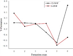
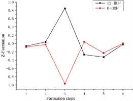
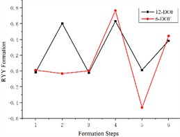
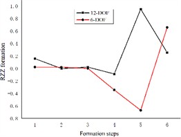
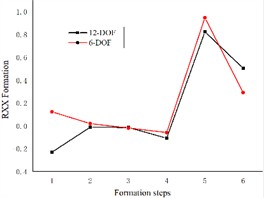
Based on the differential equations describing the dynamics of the 6-degree-of-freedom and 12-degree-of-freedom engine mount systems presented in the previous section, we solve the corresponding formation equations. The resulting formations for both systems are illustrated in Fig. 3.
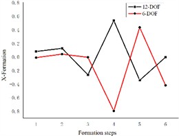
Fig. 3Comparison of 6-degree-of-freedom and 12-degree-of-freedom engine mount system formations
a)
b)
c)
d)
e)
f)
Fig. 3 illustrates the differences between the 6-degree-of-freedom and 12-degree-of-freedom engine mount systems as they rotate the formation along and around the three coordinate axes. The variables y, x, z, RXX (pitch), RZZ (droop), and RYY (sideways inclination) are numbered sequentially from 1 to 6 in the graph. The figure demonstrates significant differences in the formations of each engine mounting system when considering the elastic base of the body. Specifically, the formation in the X-direction is represented by both the X-direction and the RYY direction. The maximum variation in the Z-direction is observed in the vertical direction, while the Y-direction is represented by the RYY direction. The pitch direction is associated with the x-direction, the droop direction is reflected in the RZZ direction, and the sideways inclination is represented by both the x-direction and the RZZ direction. Consequently, treating the engine as a six-degree-of-freedom system mounted on a rigid base led to accuracy issues, underscoring the necessity of examining it on an elastic base.
3.2. Sensitivity analysis of three-way stiffness of engine mounts under elastic base
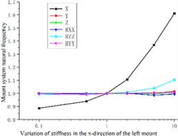
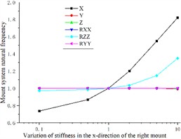
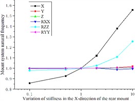
To facilitate the observation of the impact of engine mount stiffness in three directions on the system’s natural frequency, the stiffness is incrementally increased by factors of 0.1, 0.5, 1, 2, 5, and 10. This variation allows for the analysis of the natural frequency changes in the engine mount system, with the natural frequency of the coupled system being normalized for comparison.
Fig. 4 shows that by changing the left engine mount, right engine mount, and rear engine mount in the X-direction stiffness, the X-direction natural frequency of the engine mount coupling system increases as the X-direction stiffness of the engine mount increases. Also, there is some influence in the Z direction. However, the right engine mount and the rear engine mount are more sensitive to the natural frequency of the coupled system in the Z-direction relative to the left engine mount. The X-direction stiffness change has almost no change in the other directions of the engine mount coupling system's natural frequency.
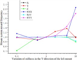
The stiffness of the left engine mount in the Y-direction exhibits significant sensitivity to the Y-direction (transverse) natural frequency of the engine mount coupling system. Specifically, lower values of Y-direction stiffness are more sensitive to transverse sway and pitch of the coupled system, whereas higher values of stiffness in the Y-direction predominantly influence the lateral inclination intrinsic frequency of the system. Despite these variations, changes in Y-direction stiffness have minimal impact on the longitudinal and vertical directions of the coupled system, as illustrated in Fig. 5(a).
Fig. 4Effect of engine mount X-direction stiffness variation on the natural frequency of the engine mount system
a)
b)
c)
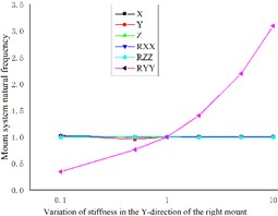
Similarly, increasing the Y-direction stiffness of the right engine mount results in a higher pitch natural frequency of the coupled system. However, this adjustment has negligible effects on the natural frequencies in the other five directions, as shown in Fig. 5(b).
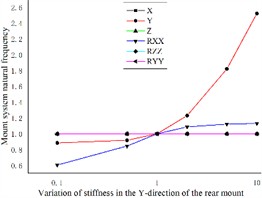
The impact of varying the Y-direction stiffness of the rear engine mount on the transverse intrinsic frequency of the coupled system mirrors that of the left engine mount, with an increase in stiffness leading to a higher transverse frequency. Additionally, lower stiffness values are more sensitive to changes in the pitch intrinsic frequency of the coupled system, while having minimal effect on the natural frequencies of the remaining four directions, as depicted in Fig. 5(c).
Fig. 5Effect of engine mount Y-direction stiffness variation on the natural frequency of the engine mount system
a)
b)
c)
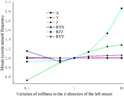
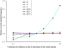
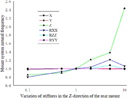
The impact of varying the Z-direction stiffness of the three engine mounts on the coupled system’s droop is distinct. Specifically, the left and right engine mounts exhibit greater sensitivity to changes in the vertical natural frequency of the coupled system at lower Z-direction stiffness values. Conversely, the vertical natural frequency of the coupled system increases with rising Z-direction stiffness values, as indicated in Figs. 6(a) and 6(c). Additionally, the right engine mount significantly influences the transverse sway and pitch natural frequencies of the coupled system. Notably, at higher stiffness values, the pitch natural frequency of the coupled system increases markedly, as illustrated in Fig. 6(b).
By analyzing the effects of different engine mount stiffnesses on the 12-degree-of-freedom elastic base engine coupled system, it is observed that the Z-direction stiffness of the rear engine mount has the greatest sensitivity to the vertical natural frequency of the coupled system. In contrast, the Z-direction stiffness values of the left and right engine mounts also influence the coupled system’s vertical natural frequency, though to a lesser extent. The most significant impacts on the lateral sway natural frequency of the coupled system are attributable to the Z-direction stiffness of the right engine mount, as well as the Y-direction stiffness values of the left and rear engine mounts. Additionally, the Y-direction stiffness of the right engine mount, along with the lower Y-direction stiffness of the left engine mount, shows heightened sensitivity to the pitch natural frequency of the coupled system.
Fig. 6Effect of engine mount Z-direction stiffness variation on the natural frequency of the engine mount system
a)
b)
c)
4. Sensitivity and vibration isolation analysis of engine mount system with 12-degree-of-freedom elastic base
4.1. Sensitivity analysis
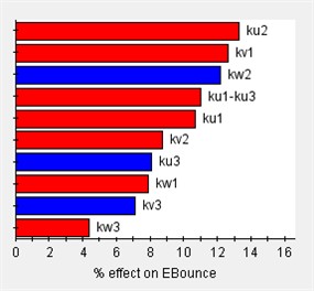
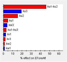
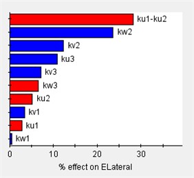
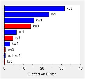
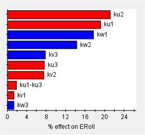
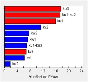
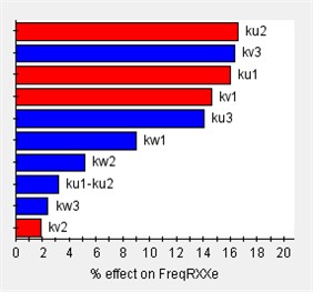
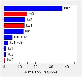
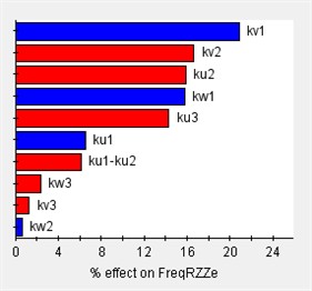
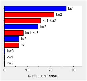
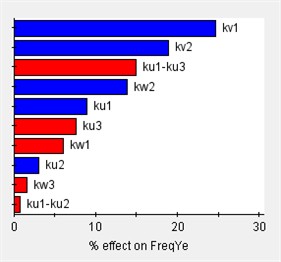
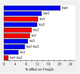
Based on the vibration differential equations of a 12-degree-of-freedom engine mount system Eq. (29), the sensitivity of the system to variations in engine mount stiffness can be analyzed using Isight software. In this analysis, (1) the design variables consist of 12 parameters corresponding to the stiffness of each engine mount, and (2) the output responses are the rigid body modal frequencies and the decoupling rates. The Pareto plot of the output sensitivity and the corresponding results are presented in Fig. 7.
Fig. 7Sensitivity of engine mount parameters for each direction
a)
b)
c)
d)
e)
f)
g)
h)
i)
j)
k)
l)
Before optimizing the engine mounting parameters, it is essential to first determine the value range of the design variables. The sensitivity of these variables to the design response varies across different value ranges; therefore, sensitivity analysis can identify the intervals with high sensitivity, which should be considered for the design variables’ value range. As illustrated in Fig. 7, the stiffness of the 12-degree-of-freedom engine mount system exhibits varying sensitivities in different directions, directly impacting the system's vibration isolation effectiveness.
4.2. Vibration isolation performance analysis
According to Eq. (12) and Eq. (29), it is possible to obtain the effect of considering the elastic action of the car body on the vibration isolation performance of the engine mount system for the same excitation.
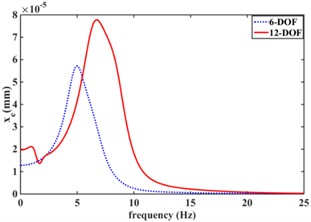
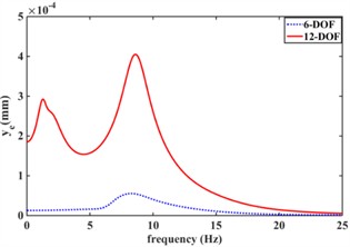
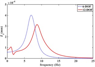
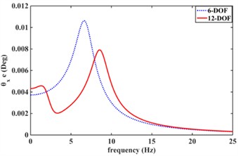
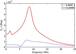
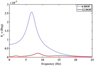
Fig. 8 shows the effect of an elastic car body on the vibration isolation performance of the engine mount system. Fig. 8(a) shows the frequency response characteristics of the engine center-of-mass displacement response in the xe direction considering body elasticity (12-DOF) versus (6-DOF) without considering the effect of car body elasticity; Fig. 8(b) shows the frequency response characteristics of engine center-of-mass displacement response aroundyedirection considering body elasticity (12-DOF) and without body elasticity (6-DOF); Fig. 8(c) shows the frequency response characteristics of engine center-of-mass displacement response around ze direction considering body elasticity (12-DOF) and without body elasticity (6-DOF); Fig. 8(d) shows the frequency response characteristics of engine center-of-mass displacement response around x direction considering car body elasticity (12-DOF) and without body elasticity (6-DOF); and Fig. 8(e) shows the frequency response characteristics of engine center-of-mass displacement response around x direction considering car body elasticity (12-DOF) and without Fig. 8(d) shows the frequency response characteristics of the engine center of mass displacement response in the x-direction with and without considering the body elasticity (6-DOF); Fig. 8(e) shows the frequency response characteristics of the engine center of mass displacement response in the Y-direction with and without considering the car body elasticity (12-DOF); Fig. 8(f) shows the frequency response characteristics of the engine center of mass displacement response in the z-direction with and without considering the car body elasticity (6-DOF); and Fig. 8(g) shows the frequency response characteristics of the engine center of mass displacement response in the z-direction with and without considering the car body elasticity (6-DOF). frequency response characteristics around the Z-direction. From Fig. 8, the car body elasticity has a great influence on the vibration isolation performance of the engine mount system. Meanwhile, the displacement frequency response of the engine center of mass of the 12-degree-of-freedom engine mount system considering car body elasticity all has two resonance peaks; The 6-degree-of-freedom engine mount system without considering the effect of body elasticity has only one resonance peak. This is mainly due to the resonance of the body’s intrinsic frequency within 5 Hz, and due to the coupling effect between the engine and the car body.
Fig. 8Effect of elastic car body on vibration isolation performance of engine mount system
a)
b)
c)
d)
e)
f)
4.3. Decoupling optimization
The objective of optimizing the engine mount system is to reduce the coupling among different modes, appropriately configure the modal frequencies of each mode, and enhance the system's vibration isolation performance. To achieve this, this paper focuses on optimizing the 12-degree-of-freedom engine suspension system by considering the car body’s impact. The goal is to maximize the decoupling rate for the first six modes while minimizing the car body displacement response. The following sections describe the design of the objective function, the selection of design variables, the setting of constraints, and the choice of optimization algorithms.
(1) Design of the objective function.
The object of this study is for a 4-cylinder engine, with the engine 6th order decoupling rate maximum and body vibration displacement response as the objective function. The specific objective function is designed as the following equation:
where, Txe, Tye, Tze, Tθxe, Tθuye, Tθze are the decoupling rates of the 6th order vibration of the engine of the 12-degree-of-freedom engine mount system considering the body influence, and qccar body displacement response.
(2) Design variables.
Engine mount stiffness and mounting position directly affect the degree of coupling of the engine mount system. Therefore, engine mount stiffness and mounting position are used as design variables for decoupled optimization of the engine mount system. At the same time, the number of engine mounts in this study is n=3. The range of values selected for the specific engine mount stiffness and mounting position are shown below.
Left engine mounting location:
Right engine mount mounting position:
Rear engine mount mounting location:
Left engine mount stiffness:
Right engine mount stiffness:
Rear engine mount stiffness:
(3) Constraints.
The idle speed of the 4-cylinder engine is 750 r/min, which corresponds to an excitation frequency of 25 Hz. Consequently, to avoid resonance, the natural frequency around the crankshaft should be less than 1/√2 times the idle excitation frequency, which is approximately 17 Hz. To prevent resonance, the natural frequencies of the engine mounting system must not coincide with each other, the intrinsic body frequency (1-3 Hz), or the unsprung mass beating frequency (15-18 Hz). Therefore, the frequency range of the first six modes of the 12-degree-of-freedom engine mount system, considering the influence of the car body, should be controlled between 5 and 15 Hz. Additionally, the modal frequencies of the engine mount system should be spaced at least 1 Hz apart to avoid overlap. In summary, the mathematical model for optimizing the decoupling of the 12-degree-of-freedom engine mount system is established with these considerations:
(4) Optimization methods.
The NLPQL algorithm has a fast convergence speed for multi-objective optimization problems, and good results are obtained by applying NLPQL to the decoupled optimization of the engine mount system. Therefore, the optimization algorithm of the 12-degree-of-freedom engine mount system considering the body displacement response adopts the NLPQL algorithm. The specific steps are: (1) Prepare the program to solve the decoupling degree and intrinsic frequency of the 12-degree-of-freedom system as well as the vibration displacement response of the body; (2) Set up the input/output variables, constraints, optimization objective, and optimization algorithm in the software; and (3) Select NLPQL as the optimization algorithm to obtain the maximum value of the decoupling rate of the engine in the 6th order as well as the minimum value of the vibration displacement response of the car body.
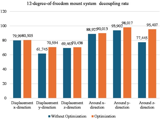
Fig. 9Comparison of decoupling ratio of each order of engine mount system before and after optimization
4.4. Analysis of optimization results
Fig. 9 shows that the decoupling rate of the engine mount system in the X-direction increases from 79.99 % to 80.505 %; the decoupling rate of the engine mount system in the Y-direction increases from 61.745 % to 70.594; and the decoupling rate of the engine mount system in the z-direction increases from 69.463 % to 70.438 %; similarly, the decoupling rate of the engine mount system around the X-direction increases from the original 88.927 % to 90.013 %; the decoupling rate of the engine mount system around the Y-direction increased from 93.902 % to 98.017 %; and in the engine mount system around the Z-direction the decoupling rate increased from 77.445 % to 95.407 %.
5. Conclusions
The main innovation of the article is the introduction of engine excitation and the consideration of body vibration for the decoupled optimization design of the 12 DOF mount system. In the article, the NLPQL algorithm for 12 DOF mount systems with maximum mount decoupling ratio and minimum engine displacement response is simultaneously considered to optimize the suspension position and stiffness to achieve the best vibration isolation performance of the mount system. The dynamics of engine mount systems with 6 degrees of freedom (DOF), 9 DOF, and 12 DOF have been modeled. The intrinsic frequencies, corresponding mode shapes, and decoupling rates of these systems are analyzed. A comparative study investigates the differences in natural frequencies among the 6-DOF, 9-DOF, and 12-DOF engine mount systems. The 12-DOF engine mount system, which demonstrates the highest decoupling rate in the first six modes and the lowest displacement response of the car body, is chosen as the target for multi-objective optimization. In this optimization, engine mount stiffness and mounting position are treated as design variables. It is shown that connecting the lower point of the engine mount directly to a rigid foundation improves the accuracy of the results. A comparison between the traditional 6-DOF system and the 12-DOF engine mount system with an elastic foundation reveals significant differences in the sixth mode. Variations in the stiffness of the 3-point engine mount, including the stiffness values in the X-, Y-, and Z-directions, significantly influence the system’s sensitivity to each natural frequency mode. Furthermore, the decoupling rate of each mode in the 12-DOF engine mount system is significantly enhanced by employing the NLPQL algorithm.
References
-
Y. Yu, N. G. Naganathan, and R. V. Dukkipati, “A literature review of automotive vehicle engine mounting systems,” Mechanism and Machine Theory, Vol. 36, No. 1, pp. 123–142, Jan. 2001, https://doi.org/10.1016/s0094-114x(00)00023-9
-
J. Wu and W.-B. Shangguan, “Robust optimization design method for powertrain mounting systems based on six sigma quality control criteria,” International Journal of Automotive Technology, Vol. 11, No. 5, pp. 651–658, Sep. 2010, https://doi.org/10.1007/s12239-010-0077-2
-
T. Jeong and R. Singh, “Analytical methods of decoupling the automotive engine torque roll axis,” Journal of Sound and Vibration, Vol. 234, No. 1, pp. 85–114, Jun. 2000, https://doi.org/10.1006/jsvi.1999.2860
-
E. Courteille, F. Mortier, L. Leotoing, and E. Ragneau, “Multi-objective robust design optimization of an engine mounting system,” in SAE 2005 Noise and Vibration Conference and Exhibition, May 2005, https://doi.org/10.4271/2005-01-2412
-
J.-Y. Park and R. Singh, “Effect of non-proportional damping on the torque roll axis decoupling of an engine mounting system,” Journal of Sound and Vibration, Vol. 313, No. 3-5, pp. 841–857, Jun. 2008, https://doi.org/10.1016/j.jsv.2007.12.007
-
J.-Y. Park and R. Singh, “Role of spectrally varying mount properties in influencing coupling between powertrain motions under torque excitation,” Journal of Sound and Vibration, Vol. 329, No. 14, pp. 2895–2914, Jul. 2010, https://doi.org/10.1016/j.jsv.2010.01.031
-
J. Liette, “New paradigms to control coupled powertrain and frame motions using concurrent passive and active mounting schemes,” 2014.
-
B. Tan, Y. Chen, Q. Liao, B. Zhang, N. Zhang, and Q. Xie, “A condensed dynamic model of a heavy-duty truck for optimization of the powertrain mounting system considering the chassis frame flexibility,” Proceedings of the Institution of Mechanical Engineers, Part D: Journal of Automobile Engineering, Vol. 234, No. 10-11, pp. 2602–2617, Apr. 2020, https://doi.org/10.1177/0954407020909241
-
B. Angrosch, M. Plöchl, and W. Reinalter, “Mode decoupling concepts of an engine mount system for practical application,” Proceedings of the Institution of Mechanical Engineers, Part K: Journal of Multi-body Dynamics, Vol. 229, No. 4, pp. 331–343, Jan. 2015, https://doi.org/10.1177/1464419314564020
-
L.-E. Ooi and Z. M. Ripin, “Optimization of an engine mounting system with consideration of frequency-dependent stiffness and loss factor,” Journal of Vibration and Control, Vol. 22, No. 10, pp. 2406–2419, Sep. 2014, https://doi.org/10.1177/1077546314547532
-
H. Zhou, H. Liu, P. Gao, and C.-L. Xiang, “Optimization design and performance analysis of vehicle powertrain mounting system,” Chinese Journal of Mechanical Engineering, Vol. 31, No. 1, pp. 76–88, Apr. 2018, https://doi.org/10.1186/s10033-018-0237-2
-
N. H. Trưởng and D.-N. Dao, “New hybrid between NSGA-III with multi-objective particle swarm optimization to multi-objective robust optimization design for Powertrain mount system of electric vehicles,” Advances in Mechanical Engineering, Vol. 12, No. 2, p. 168781402090425, Feb. 2020, https://doi.org/10.1177/1687814020904253
-
B. Cai, W.-B. Shangguan, and H. Lü, “An efficient analysis and optimization method for the powertrain mounting system with hybrid random and interval uncertainties,” Engineering Optimization, Vol. 52, No. 9, pp. 1522–1541, Sep. 2020, https://doi.org/10.1080/0305215x.2019.1663187
-
H. Lü, K. Yang, X. Huang, W.-B. Shangguan, and K. Zhao, “Uncertainty and correlation propagation analysis of powertrain mounting systems based on multi-ellipsoid convex model,” Mechanical Systems and Signal Processing, Vol. 173, p. 109058, Jul. 2022, https://doi.org/10.1016/j.ymssp.2022.109058
-
J. Wu, X. Liu, Y. Shan, and T. He, “Robustness optimization of engine mounting system based on Six Sigma and torque roll axis decoupling method,” Proceedings of the Institution of Mechanical Engineers, Part D: Journal of Automobile Engineering, Vol. 233, No. 4, pp. 1047–1060, Mar. 2018, https://doi.org/10.1177/0954407018755247
-
J.-F. Hu and R. Singh, “Improved torque roll axis decoupling axiom for a powertrain mounting system in the presence of a compliant base,” Journal of Sound and Vibration, Vol. 331, No. 7, pp. 1498–1518, Mar. 2012, https://doi.org/10.1016/j.jsv.2011.11.022
-
J. M. Lee, H. J. Yim, and J.-H. Kim, “Flexible chassis effects on dynamic response of engine mount systems,” in International Conference on Vehicle Structural Mechanics and Cae, Apr. 1995, https://doi.org/10.4271/951094
-
W.-B. Shangguan, X.-A. Liu, Z.-P. Lv, and S. Rakheja, “Design method of automotive powertrain mounting system based on vibration and noise limitations of vehicle level,” Mechanical Systems and Signal Processing, Vol. 76-77, pp. 677–695, Aug. 2016, https://doi.org/10.1016/j.ymssp.2016.01.009
About this article

The authors have not disclosed any funding.
The datasets generated during and/or analyzed during the current study are available from the corresponding author on reasonable request.
Mingzhong Wu: conceptualizing and writing. Zhihong Lin: proofreading. Liji Su: translating.
The authors declare that they have no conflict of interest.
