Abstract
The nonlinear vibration and dynamic stress characteristics of disc brakes are key factors affecting braking noise and safety. Based on the working principle of disc brake, a six-degree-of-freedom dynamic model was constructed, and the amplitude-frequency response of vibration under diverse braking pressures and initial velocities was acquired. The modal characteristics of the brake disc were computed using the finite element simulation approach, and the natural frequency and vibration mode were obtained. The accuracy of the modal calculation was verified by means of the laser detection method. In order to study the dynamic stress variation law more accurately, a coupled model of temperature and displacement was established, and transient stresses on different paths were obtained. The results indicate that the finite element model has high accuracy, with a maximum calculation error of only 5.1 % for the natural frequency. Besides, temperature variations will lead to thermal deformation of the brake disc, which intensifies the random vibration characteristics associated with the friction process.
Highlights
- Based on the working principle of disc brake, a six-degree-of-freedom dynamic model was constructed, and the amplitude-frequency response of vibration under diverse braking pressures and initial velocities was acquired.
- The modal characteristics of the brake disc were computed using the finite element simulation approach, and the natural frequency and vibration mode were obtained.
- The accuracy of the modal calculation was verified by means of the laser detection method.
1. Introduction
During the braking process of a vehicle, the friction between the brake pads and brake discs in the braking system is the fundamental cause of random vibrations and noise in the system [1, 2]. In the braking system, the presence of friction causes wear on key components of the friction pair, resulting in gaps and uneven contact surfaces between the brake pads and brake discs. Friction components are prone to collisions and frictional vibrations, which can exacerbate wear and generate braking noise, and are more likely to cause resonance phenomena. Therefore, modal analysis is indispensable [3, 4]. The natural frequency and modal shape are also key criteria for predicting frictional vibration and noise. If the braking system design of the vehicle is not reasonable, vibration may occur during braking when the car is running at low speeds [5]. The vibration motion that occurs in the braking system during the vehicle braking process is a self-excited vibration, which not only reduces the braking efficiency and stability, but also has a certain damage effect on the equipment inside the vehicle and the vehicle braking system, affecting the normal driving and parking of the vehicle, and endangering the safety of passengers on board. From an economic perspective, experimental methods are not the preferred solution. Vibration and flutter research is a new branch of vehicle dynamics, which supplements and improves vehicle dynamics. With the development of computer simulation technology, studying and ensuring the stability of braking systems through progressive dynamic analysis and coupled modeling is an effective and scientific technical means.
2. Nonlinear vibration analysis
2.1. Model establishment and simplification
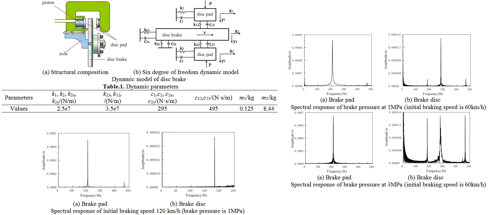
Typically, disc brake is composed of brake caliper body, brake pad, brake disc, and piston as shown in Fig. 1(a). The brake disc is made of alloy steel and fixed on the wheel, rotating with the wheel. The cylinder is fixed on the bottom plate of the brake and remains stationary. They move together with the piston and apply braking force to the brake disc after friction with the brake disc. Based on the installation method and working state of the disc brake [6], a dynamic model with multi degree of freedom characteristics is constructed and analyzed, as shown in Fig. 1(b). Under ideal conditions, assuming that the quality and structure of the different parts are balanced. The mass of the fixed friction plate, brake disc, and movable friction plate is , , and , respectively. The supporting stiffness of the upper and lower friction plates are and , respectively, and the damping and are equal to each other. The contact attributes of the friction pair surface can be expressed as , , , , , , , respectively. Let the horizontal displacement of brake pads and brake discs be , , and . The normal displacements are , , and .
Fig. 1Dynamic model of disc brake
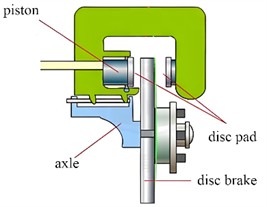
a) Structural composition
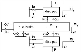
b) Six degree of freedom dynamic model
Table 1Dynamic parameters
Parameters | , , , / (N/m) | , , / (N/m) | , , , / (N·s/m) | , / (N·s/m) | / kg | / kg |
Values | 2.5e7 | 3.5e7 | 295 | 495 | 0.125 | 8.44 |
2.2. Vibration response under different braking conditions
(1) The influence of brake pressure on vibration. Under different brake pressure load conditions, the amplitude frequency response results of the vibration process of brake pads and brake discs can be calculated, as shown in Fig. 2 and Fig. 3, respectively. It can be inferred that within the maximum external excitation frequency range, the main frequencies of resonance between brake pads and brake discs are different, at 210 and 300 Hz, respectively. The brake pressure has a significant impact on the frequency response. If the braking pressure is increased, the feedback generated by the excitation vibration will be more significant, because the contact stiffness and damping have chaotic characteristics, which are one of the key factors affecting the amplitude.
Fig. 2Spectral response of brake pressure at 1 MPa (initial braking speed is 60 km/h)
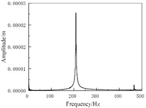
a) Brake pad
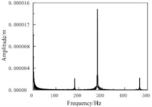
b) Brake disc
Fig. 3Spectral response of brake pressure at 3 MPa (initial braking speed is 60 km/h)
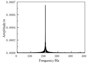
a) Brake pad
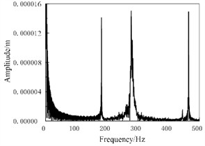
b) Brake disc
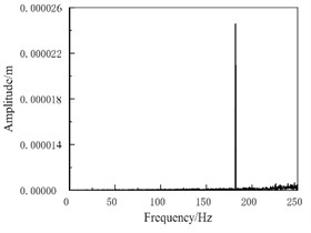
(2) The influence of initial braking speed on vibration. Under the condition of initial braking speed of 120 km/h, the spectral response results are shown in Fig. 4. It can be seen that as the initial braking speed increases, the vibration frequency gradually concentrates towards the main frequency, the main vibration frequency gradually protrudes, and the amplitude gradually increases. This is because as the initial braking speed gradually increases, the period of the system’s stick slip vibration will shorten, and the slope of the displacement growth of the brake pad during the adhesion stage will increase. When the speed increases to a certain extent, the stick slip motion gradually evolves into pure slip motion, and vibrations different from the main frequency also disappear.
Fig. 4Spectral response of initial braking speed 120 km/h (brake pressure is 1 MPa)
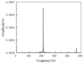
a) Brake pad
b) Brake disc
2.3. Modal calculation and discussion
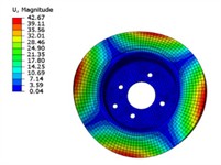
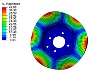
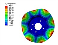
The simulation results of modal shapes are shown in Fig. 5. It can be seen that the maximum displacement of each modal vibration mode of the brake disc occurs at the circumferential edge of the disc perpendicular to the pitch direction, and the part where the maximum displacement occurs is symmetrically distributed on the brake disc. As the modal order increases, the number of pitch diameters of the brake disc also increases, and the brake disc is divided into more deformation intervals. However, the overall displacement and pitch diameter distribution of the brake disc are roughly similar, symmetrically distributed along the radial axis passing through the center of the disc. The maximum displacement difference between the modal shapes of each order is relatively small, which is due to the increase in brake disc frequency, resulting in an increase in the number of brake disc pitch diameters. The brake disc vibration modes are divided into smaller intervals, thereby weakening the influence on the deformation displacement of the brake disc.
The experimental mode adopts laser testing method, which requires fixing the brake disc on the test bench and applying excitation to the brake disc using an exciter, as shown in Fig. 6. The microphone transmits the vibration signal of the brake disc to the computer, and the laser vibrometer transmits the modal vibration signal of the brake disc to the computer. The collected signal is processed by the computer to obtain the modal frequency of the brake disc. The comparison between the experimental test results and the simulation results is shown in Table 2. It can be seen that the error between the modal test and modal analysis frequency of the brake disc is within 5.1 %, which is within a controllable range. Therefore, the finite element model of the disc brake established is accurate.
Fig. 5Modal shapes
a) The first order
b) The second order
c) The third order
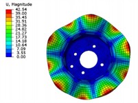
d) The fourth order
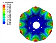
e) The fifth order
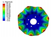
e) The sixth order
Fig. 6Modal testing scheme
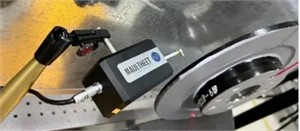
Table 2The first six natural frequencies by modal simulation and testing
Order | 1 | 2 | 3 | 4 | 5 | 6 |
Calculated nature frequency / Hz | 683.2 | 896.4 | 1015.3 | 1620.8 | 2167.4 | 3280.5 |
Tested nature frequency / Hz | 662.8 | 873.3 | 988.9 | 1542.7 | 2144.7 | 3205.1 |
Deviation results / % | 3.1 % | 2.6 % | 2.7 % | 5.1 % | 1.1 % | 2.4 % |
3. Transient stress analysis
3.1. The establishment of thermal machine coupling model
Early research on brake friction was mainly conducted through experimental methods. However, due to the complex and variable actual working conditions, the reproducibility of experimental research is poor and the cost is high. Establish the finite element model of the friction pair as shown in Fig. 7(a), using hexahedral scanning method for mesh division and local refinement, and selecting temperature and displacement coupling as the analysis module. During the braking process, the contact surface of the friction pair mainly conducts heat. Introduce heat flux density into the friction contact area between the brake disc and brake pad, and apply boundary conditions on the non-contact surface of the model. When the brake pads and brake discs rub against each other during braking, the speed of heat conduction inside the object is lower than the speed of heat generated by friction, resulting in a temperature gradient on the brake disc surface and varying degrees of thermal deformation of the brake disc unit, leading to uneven stress distribution on the brake disc. So it is necessary to choose a suitable material with a thermal conductivity coefficient to achieve temperature transmission between the contact and non-contact areas, which is more in line with reality and increases the realism of the simulation.
When the brake pad comes into contact with the brake disc, the brake pad can only move in the normal direction of the contact surface, while the brake disc can rotate in the normal direction and be fixed in other directions to ensure sufficient friction between the brake pad and the brake disc. The magnitude of the friction coefficient is related to temperature changes, while the magnitude of the friction force is determined by the friction coefficient and the pressure applied to the brake pads. For the motion of the friction pair, a coupling node is established at the center of the brake disc using degrees of freedom constraints. Couple the node with the surrounding protrusions and set the rotational angular velocity of the point to achieve the rotation of the brake disc. Apply a load on the surface of two brake pads to simulate the actual braking force, so that the brake pads and brake discs are in contact with each other, and achieve frictional braking when the brake discs rotate. To analyze the variation law of dynamic stress in different directions, two paths are set up, as shown in Fig. 7(b) and Fig. 7(c), respectively.
Fig. 7The establishment of FEA model and path setting
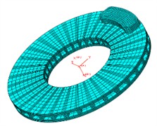
a) Model of the friction pair
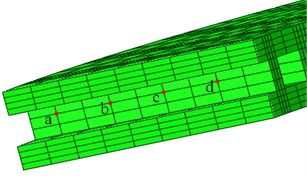
b) Path in rib direction
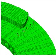
c) Path in end face direction
3.2. Discussion of transient stress results
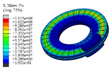
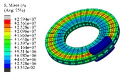
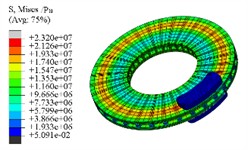
The transient stress field cloud map of the brake at different time intervals is illustrated in Fig. 7. It is evident that the hot spot phenomenon within the stress distribution is quite pronounced. Key factors affecting this stress field include pressure, friction, and temperature, with the peak stress consistently found on the friction surface. Following 1th second, the forces acting between the friction pairs are released, leading to a situation where temperature changes primarily dictate the characteristics of the stress field observed at that moment. At 10th second, the maximum stress value remains approximately on the order of 107. The dynamic distribution of residual stresses can reflect the degree of equilibrium in surface deformation. If the magnitude and gradient of residual stress are small, this will be beneficial in reducing the noise and vibration of the friction pair.
Fig. 8Transient stress results
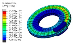
a) 0.5 s
b) 1.0 s
c) 5 s
d) 10 s
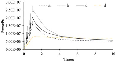
The stress curves of the brake disc in the time domain for various paths are illustrated in Fig. 9. It is evident that throughout the braking process, the stress at the friction surface nodes (nodes 1 to 4) displays a sawtooth-like upward trend in the radial direction, with node 2, located at the center of the brake pad, experiencing the highest stress levels. In the interval from 0 to 1 second, node 5 shows quite significant fluctuations in stress. However, its distance from the friction surface results in it maintaining a relatively low value. The stress variation law of the end face path markedly differs from that of the rib face, particularly during the braking stage, where the phenomenon of stress mutation is highly conspicuous. This is because the brake pads have a direct compressive impact on the ribs. When the brake pads pass over this node, the stress instantaneously decreases with virtually no time-delay phenomenon. After the brake pressure is released, the stress at node d gradually increases to a stable state, while the stress at nodes a to c sharply declines and gradually stabilizes. Due to the distance of node d from the heat source, its temperature keeps rising. Under the condition where stress is dominated by temperature, the stress of node d is greater than that of nodes a to c.
Fig. 9Stress changes on different paths
a) Path in rib direction
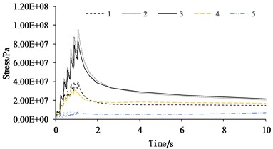
b) Path in end face direction
4. Conclusions
1) The nonlinear dynamic model of disc brake system fully considers the vibration influence of brake pads, but still has certain limitations, including not considering the dynamic change of damping characteristics and elastic stiffness of the braking system during operation, and ignoring the influence of the turning angle of the brake disc on vibration during braking. Under ideal conditions, the dynamic model established can achieve high computational accuracy. The analysis of the dynamic response of friction pairs under varying braking pressures and initial speeds reveals pronounced nonlinear vibrations in both brake pads and discs. Increasing the braking pressure enhances the stick-slip phenomenon, leading to a more pronounced chaotic behavior in the friction pair. Additionally, raising the initial braking speed increases the system’s kinetic energy, resulting in a significant rise in vibration amplitude for the friction pair.
2) Considering the influence of temperature field, a temperature displacement coupling model for disc brakes was established, and the transient stress variation laws in different directions were obtained. It can be known that the nodal stress on the brake disc exhibits a sawtooth-like upward trend in different directions, which is also one of the important reasons for the occurrence of local random noise and vibration.
References
-
A. Kim, M. Doudkin, A. Ermilov, G. Kustarev, M. Sakimov, and M. Mlynczak, “Analysis of vibroexciters working process of the improved efficiency for ice breaking, construction and road machines,” Journal of Vibroengineering, Vol. 22, No. 3, pp. 465–485, May 2020, https://doi.org/10.21595/jve.2020.20446
-
R. D. Nascimento Rodrigues et al., “Analysis of geometric and material parameters in the modal stability of wind turbine brakes using the complex eigenvalue method,” Noise and Vibration Worldwide, Vol. 55, No. 8, pp. 438–453, Aug. 2024, https://doi.org/10.1177/09574565241270210
-
A. Ghorbel, B. Zghal, M. Abdennadher, L. Walha, and M. Haddar, “Investigation of friction-induced vibration in a disk brake model, including mode-coupling and gyroscopic mechanisms,” Proceedings of the Institution of Mechanical Engineers, Part D: Journal of Automobile Engineering, Vol. 234, No. 2-3, pp. 887–896, May 2019, https://doi.org/10.1177/0954407019845723
-
M. Sohrabifard, M. Nategh, and M. Ghazavi, “Evaluation, calibration, and modal analysis for determination of contact stiffness between workpiece and components of milling fixture,” Proceedings of the Institution of Mechanical Engineers, Part B: Journal of Engineering Manufacture, Vol. 237, No. 12, pp. 1819–1835, Nov. 2022, https://doi.org/10.1177/09544054221138165
-
Y. He, Y. Ding, S. Mohrmann, and Z. Wang, “Experimental and finite element method study on dynamic characteristics of beam-column glulam frame structure,” Advances in Structural Engineering, Vol. 25, No. 13, pp. 2738–2753, Jun. 2022, https://doi.org/10.1177/13694332221107577
-
G. Y. Pan and Y. K. Feng, “Improved design of disc brake vibration based on spring contact dynamics model between disk and block,” Vibration and Shock, Vol. 41, No. 17, pp. 244–253, Sep. 2022, https://doi.org/10.13465/j.cnki.jvs.2022.17.030
About this article
The authors have not disclosed any funding.
The datasets generated during and/or analyzed during the current study are available from the corresponding author on reasonable request.
The authors declare that they have no conflict of interest.
