Abstract
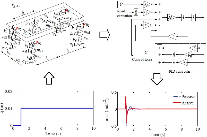
To evaluate the control performance of the PID controller for the cars, a 3D car dynamic model with 8-DOF which can fully reflect the pitch and roll of the car body is proposed in this study. The PID controller is then researched and applied to control the active suspension system of the cars under the different excitations of the road surface and the various car speeds. The control performance for improving the ride comfort of the driver is evaluated via the root-mean-square (RMS) of acceleration responses of the vertical driver’s seat, pitching and rolling car body angles. The research results show that the PID controller for the car suspension system have an obvious impact on reducing the vibration and controlling the car body shaking in comparison with the passive suspension system.
Highlights
- The RMS values with the PID controller are remarkably reduced by 19.3, 18.3, and 24.7% in comparison without the control, respectively.
- Under the various car speeds, the RMS values are also greatly reduced in comparison with the passive suspension system, especially at a car speed range from 40 to 60 km/h.
- The results of this study also show that the car ride comfort has been greatly increased by using the PID controller under various operating conditions, while the structure of the PID controller is relatively simple.
1. Introduction
Nowadays, due to the demand for transport development, all vehicles need to travel at a higher speed, safer, and more stable, particularly the cars. In order to solve this problem, the car suspension system is especially concerned by the researches. The car suspension system equipped with the spring and damping mounts was researched and replaced by using the air suspension system [1, 2]. The car’s ride comfort was significantly improved. However, the structure of the air suspension is quite complex to equip on cars. Therefore, the study for controlling the damping force or coefficients of the suspension system had been concerned. The vehicle suspension system model with the damping coefficient of the magneto-rheological (MR) fluid was researched and controlled [3-8]. The root-mean-square (RMS) acceleration responses of the vehicles were chosen as the objective function of the studies [9-11]. The results showed that the damper force of the RM could improve the vehicle ride comfort.
To enhance the control performance of the semi-active suspension system using the MR fluid mount [7, 8], a half vehicle with 5-DOF was controlled by the FLC controller [12], FLC-Skyhook [13], or skyhook control in Matlab/Simulink and Adams software [14]. Moreover, the optimal control methods, such as Neuro-Fuzzy control with the fuzzy rules optimized by the genetic algorithm (GA) [15], Fuzzy-PID control with the control rules optimized by cultural algorithm or GA [12, 16], or Fuzzy-skyhook control using the multi-objective microgenetic algorithm [17], were successfully applied. The results showed that the optimal control methods were better than without optimization. However, the quarter car models with the damping coefficient of the MR fluid were mostly applied and controlled for all the researches. Besides, the control performance was only achieved up to 23 % [1, 3, 16], while the texture and complexity of the combined controllers may lead to reduce the stability and increase the cost of the controller. Thus, it is very difficult to apply these research results in the actual conditions. The PID control is one of the controllers with not only a simple structure but also robust performance, and it is generally used in industrial process control [5]. However, its control performance to control the vehicle suspension system has not yet been evaluated.
The innovation in this paper is that a 3D car dynamic model with 8-DOF which can fully reflect the pitch and roll of the car body is concerned under the various operating conditions. The PID controller is researched and applied to control the active force for the car suspension system. The vibration effect to the car ride comfort via the acceleration response and the RMS accelerations of the vertical driver’s seat, pitching and rolling car body angles is chosen as the objective function. The performance and stability of the PID controller are then evaluated under the various excitations of the road surface and the different speeds of the cars.
2. Material and methods
2.1. The dynamic model of cars
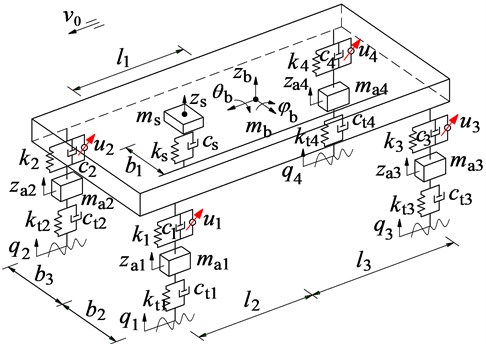
A 3D car with four independent suspensions is chosen to establish the vehicle dynamic model and control their suspension systems, as shown in Fig. 1, where , , and are the vertical displacements of the driver seat, car’s body, and four car’s axles, respectively; and are pitching and rolling angles of car’s body; , , and are the mass of the driver seat, car’s body, and four car’s axles; , and , are the damping and stiffness parameters of the suspension system and tires; is the active control force of the suspension system; and are the longitudinal and transversal distances of vehicle; is the vibration excitation of the tires, ( 1-4, 1-3).
Based on the nonlinear dynamic model of the car and by Newton’s second law of motion, the car’s dynamic equations are written by the matrix form:
where is the matrix of the mass, and are the matrix of the damping and stiffness of the suspension systems, and are the matrix of the damping and stiffness of the tires, is the matrix of the control force of the car suspension systems, there are determined in Appendix.
Fig. 1The nonlinear dynamic model of cars
2.2. PID control and application
The PID control is one of the controllers with not only a simple structure but also robust performance, and it is generally used in industrial process control [5, 12]. The performance of PID control depends on the appropriate selection of the PID’s parameters. The well-known Ziegler-Nichols technique has been used to choose the PID’s parameters to enhance the control performance when the system works under the operating conditions. The control force output of the PID controller is given by:
where is the vertical displacement of the suspension system of input PID controller; , and are the proportionality factors of output PID controller.
In the car dynamic model, there are four suspensions should be separately controlled, thus, four PID controller should be designed. However, the design process of these controllers is similar. Thus, a specific of the PID controller is designed to control the force for the active suspension system.
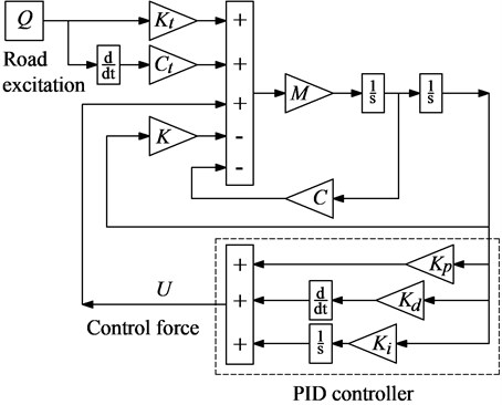
To determine the proportionality factors of the PID controller and control the system model, Eqs. (1) and (2) of the car dynamic system is solve based on Matlab/Simulink software, their model is shown in Fig. 2.
Based on the Ziegler-Nichols technique which helps for researching the optimal proportionality factors of the PID controller [5, 7], the factors of , and are obtained via the control model in Fig. 2 are 60132, 3202, and 61, the factors are then used to control the active suspension system of the cars.
Fig. 2Simulink model of the control system
2.3. Vibration excitation of the road surface
Road surface is of special interest, which impacts not only on the vehicle-road interaction but also on the vehicle’s fatigue life and the driver’s ride comfort. To analyze the control performance of the active suspension system with PID control, three types of the vibration excitation including the step, harmonic, and random road surface are considered as follows:
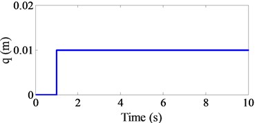
Step road surface: The bump road surface can be mathematically described by:
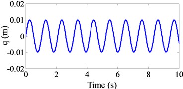
Harmonic road surface: The harmonic road surface is described as follows:
where is the excitation frequency (Hz), is the car speed (m/s), and is the car length.
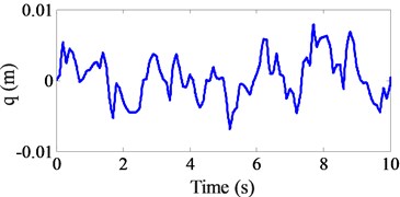
Random road surface: The random excitation of road surface roughness can be represented by a randomly modulated periodic. In the case, the form of the displacement power spectral density (PSD) of the road surface roughness is determined by the experimental formula [18]:
where is space frequency; is reference space frequency which is defined by 0.1 m-1; is the road surface roughness coefficient or PSD of the road surface under the reference space frequency ; is the frequency index which determines the frequency configuration of the PSD of the road surface (2). Road surface roughness is assumed to be a zero-mean stationary Gaussian random process. It is generated through the Fourier transformation as:
where is a random phase uniformly distributed from 0 to 2.
According to the standard ISO 8068 [18], the car speed is 72 km/h, the simulation time is 10 s, three types of the road surface excitation are plotted in Fig. 3. These vibration excitations are then used to simulate the dynamic model of cars.
Fig. 3The excitation of the various road surfaces
a) Step excitation
b) Harmonic excitation
c) Random excitation
3. Numerical simulations and discussions
3.1. Control performance under various excitations of the road surface
To emphasize clearly the control performance of the PID controller for the car’s ride comfort, assuming that the car moves at a constant speed of 72 km/h under three different cases of the road surface. The major parameter of the car listed Table 1 is used. The car dynamic model with two active and passive suspension systems is then simulated to compare the results.
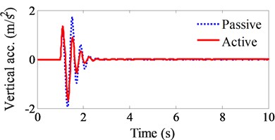
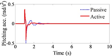
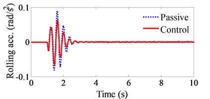
Under the step excitation of the road surface, the simulation result is plotted in Fig. 4. Observing Fig. 4(a), (b), and (c), we can see that all the acceleration responses of the vertical driver’s seat, pitching and rolling car body angles at a step of time 1 to 2 s are remarkably reduced by the active suspension system.
Table 1Major parameters of the cars
Parameter | Value | Parameter | Value | Parameter | Value |
/kg | 85 | /m | 1.604 | /N m-1 | 193211 |
/kg | 1394 | /m | 1.245 | /N m-1 | 226422 |
/kg | 66 | /m | 0.45 | /Ns m-1 | 250 |
/kg | 66 | /m | 0.9 | /Ns m-1 | 7733 |
/kg | 87 | /N m-1 | 25000 | /Ns m-1 | 9804 |
/kg | 87 | /N m-1 | 93844 | /Ns m-1 | 2000 |
/m | 1.35 | /N m-1 | 100007 | /Ns m-1 | 2000 |
Fig. 4Control performance under the step road surface
a) Vertical driver’s seat
b) Pitching body angle
c) Rolling body angle
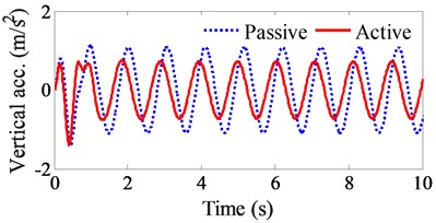
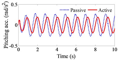
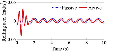
Under the harmonic excitation of the road surface, the simulation result is shown in Fig. 5. Observing Fig. 5(a), (b), and (c), we also see that the acceleration responses of the vertical driver’s seat, pitching and rolling car body angles are significantly decreased by using the PID controller for the active suspension system. Especially the acceleration values of the vertical driver’s seat and pitching cab body angle.
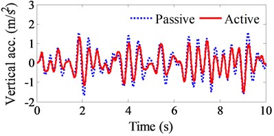
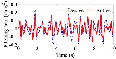
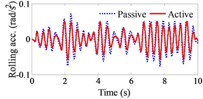
Under the random excitation of the road surface, the simulation result of the acceleration responses of the vertical driver’s seat, pitching and rolling car body angles is shown in Figs. 6(a), (b), and (c), respectively. It also finds that all their acceleration responses are clearly reduced by the PID controller.
A good suspension system should have the ability to minimize vibration transmission to improve the driver’s ride comfort based on reducing the RMS acceleration response [9-11]. Thus, the RMS values of the vertical driver’s seat, pitching and rolling body angles are calculated based on their acceleration responses are given to evaluate the control performance as follows:
where is the acceleration response of the vertical driver’s seat, pitching angle and rolling angle of the car body, is the simulation time.
Fig. 5Control performance under the harmonic road surface
a) Vertical driver’s seat
b) Pitching body angle
c) Rolling body angle
Fig. 6Control performance under the random road surface
a) Vertical driver’s seat
b) Pitching body angle
c) Rolling body angle
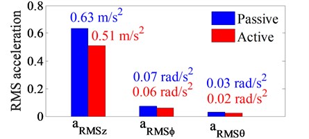
Based on the acceleration results of the driver and car body under the random road surface in Fig. 6, their RMS acceleration values are then calculated and plotted in Fig. 7. Observing Fig. 7, we can see that the RMS values of the vertical driver’s seat, pitching and rolling body angles with the active suspension system are remarkably reduced in comparison with the passive suspension system by 19.3, 18.3, and 24.7 %, respectively. This performance is due to the effect of the active force of which is controlled by the PID controller. Therefore, the driver’s ride comfort is improved by the active suspension system.
Fig. 7RMS acceleration results under the random road surface
3.2. Control performance under various speeds of car
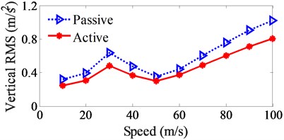
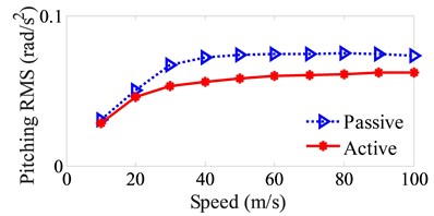
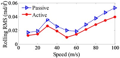
In the operating process of the car, the car speed is always changed and depended on the driver. To fully evaluate the control performance, the various speed of the car from 10 to 100 km/h is given under the random road surface. The RMS values of the vertical driver’s seat, pitching and rolling body angles are shown in Fig. 8.
Fig. 8Control performance of the RMS acceleration responses under the various car speeds
a) Vertical driver’s seat
b) Pitching body angle
c) Rolling body angle
The simulation results show that the RMS values of the vertical driver’s seat and rolling car body angle are strongly affected by the car speeds, as see in Fig. 8(a) and 8(b). Both these RMS values are the minimum at the speed range from 40 to 60 km/h and their RMS values are strongly increased from 70 to 100 km/h. However, the RMS value of the rolling car body angle affected by the speed is very small in the car speed range from 30 to 100 km/h.
The comparison results between the active and passive suspension system of the car under various car speeds, it can see that the RMS values of the vertical driver’s seat, pitching and rolling body angles are greatly reduced by the PID controller. These results also reinforce the evidence for the control performance of the PID controller. Thus, the car’s ride comfort is significantly improved not only under the different excitations of the road surface but also under the various car speeds.
4. Conclusions
The innovation in this paper is that a 3D dynamic model of the cars which can fully reflect the car body shaking vibrations is studied. The control performance of the PID controller for the active suspension system on the car driver comfort is evaluated under different operation conditions of the cars. The study results are recapitulated as follows:
1) Under the different excitations of the step, harmonic, and random road surfaces, the acceleration responses of the vertical driver’s seat, pitching and rolling body angles with the active suspension system are greatly reduced in comparison with the passive suspension system. Their RMS values with the PID controller are remarkably reduced by 19.3, 18.3, and 24.7 % in comparison without the control, respectively.
2) Under the various car speeds, the RMS values are also greatly reduced in comparison with the passive suspension system, especially at a car speed range from 40 to 60 km/h. Therefore, the active suspension system of cars applied by the PID controller can improve the car’s ride comfort under various operation conditions.
3) In the existed researches are used by the combined methods and optimal control methods [13-17], the results indicate that the vehicle ride comfort has been greatly improved. However, it is very difficult to apply these research results into the actual condition due to the high cost of the controller, which can also make the cost of the vehicles also increase. The results of this study also show that the car ride comfort has been greatly increased by using the PID controller under various operating conditions, while the structure of the PID controller is relatively simple, and its application to improve the ride comfort is entirely possible.
References
-
Liem N., Zhang I., Le V., Jiao R., Liao L. Performance analysis of air suspension system of heavy truck with semi-active fuzzy control. Journal of Southeast University, Vol. 33, Issue 2, 2017, p. 159-165.
-
Chen Y., He J., Li X., et al. Integrated performance optimum design of heavy truck air suspension based on fuzzy control. Journal of Southeast University, Vol. 38, Issue 2, 2008, p. 319-323.
-
Xie Z., Wong K., Jing Z., et al. A noise-insensitive semi-active air suspension for heavy-duty vehicles with an integrated fuzzy-wheelbase preview control. Mathematical Problems in Engineering, Vol. 2013, Issue 8, 2013, p. 121953.
-
Georgios T., Charles W., Emanuele G. Hybrid balance control of a magnetorheological truck suspension. Journal of Sound and Vibration, Vol. 317, 2008, p. 514-536.
-
Nguyen V., Zhang J., Yang X. Low-frequency performance analysis of semi-active cab’s hydraulic mounts of an off-road vibratory roller. Shock and Vibration, Vol. 2019, 2019, p. 8725382.
-
Kasemi B., Muthalif A., Rashid M., Fathima S. Fuzzy-PID controller for semi-active vibration control using magnetorheological fluid damper. Procedia Engineering, Vol. 41, 2012, p. 1221-1227.
-
Nguyen T. A Novel Semi-Active Magnetorheological Mount for Vibration Isolation. Ph.D. Thesis, The University of Toledo, Toledo, OH, USA, 2009.
-
Muthalif A., Kasemi B., Nordin D., Rashid M. Semiactive vibration control using experimental model of Magnetorheological damper with adaptive fuzzy-PID controller. Smart Structures and Systems, Vol. 20, Issue 1, 2017, p. 85-97.
-
Nguyen V., Zhang J., et al. Ride quality evaluation of the soil compactor cab supplemented by auxiliary hydraulic mounts via simulation and experiment. Journal of Southeast University (English Edition), Vol. 35, Issue 3, 2019, p. 273-280.
-
Sun X., Zhang J. Performance of earth-moving machinery cab with hydraulic mounts in the low-frequency. Journal of Vibration and Control, Vol. 20, 2014, p. 724-735.
-
Nguyen V., Zhang J., et al. Effect of the off-road terrains on the ride comfort of construction vehicles. Journal of Southeast University (English Edition), Vol. 35, Issue 2, 2019, p. 191-197.
-
Yagiz N., Sakman L., Guclu R. Different control applications on a vehicle using fuzzy logic control. Indian Academy of Sciences, Vol. 33, Issue 1, 2008, p. 15-25.
-
Yoshimura T., Isari Y., Li Q., et al. Active suspension of motor coaches using skyhook damper and fuzzy logic control. Control Engineering Practice, Vol. 5, Issue 2, 1997, p. 175-184.
-
Ieluzzi M., Turco P., Montiglio M. Development of a heavy truck semi-active suspension control. Control Engineering Practice, Vol. 14, Issue 3, 2006, p. 305-312.
-
Nguyen S., Nguyen Q., Choi S. A hybrid clustering based fuzzy structure for vibration control-Part 2: An application to semi-active vehicle seat-suspension system. Mechanical System Signal Processing, Vol. 56, Issue 57, 2015, p. 288-301.
-
Wang W., Song Y., Xue Y., Jin H., Hou J. An optimal vibration control strategy for a vehicle’s active suspension based on improved cultural algorithm. Applied Soft Computing Journal, Vol. 28, 2015, p. 167-174.
-
Chen Y., Wang Z., Qiu J., Huang Z. Hybrid fuzzy skyhook surface control using multi-objective microgenetic algorithm for semi-active vehicle suspension system ride comfort stability analysis. Journal of Dynamic Systems Measurement and Control, Vol. 134, Issue 4, 2012, p. 041003.
-
Mechanical Vibration-Road Surface Profiles-Reporting of Measured Data. International Organization for Standardization, ISO 8068, 1995.
Cited by
About this article
This study is supported by Hubei Polytechnic University Teaching and Research Projects (No. 19XJK17R).
