Abstract
For considering the connection and mutual influences between ride comfort and handing stability of a vehicle, a collaborative study on the two performances is carried out in the paper. Firstly based on the UniTire model and combined with filtered white noise models for front and real road excitations, 4-DOF plane model for ride comfort and 2-DOF plane model for handling stability, a collaborative model for ride comfort and handing stability is built by adopting state equations, and a collaborative simulation algorithm for them is also proposed. Then, a collaborative simulation on the ride comfort and handing stability of a vehicle under common road grade and speed conditions is conducted. The results show that the ride comfort and handling stability of a vehicle can be simulated simultaneously by using the collaborative model. The handling stability parameters simulated with the linear UniTire model are larger than those simulated with the nonlinear UniTire model, indicating that it is obviously conservative to study vehicle handling stability with the linear UniTire model.
Highlights
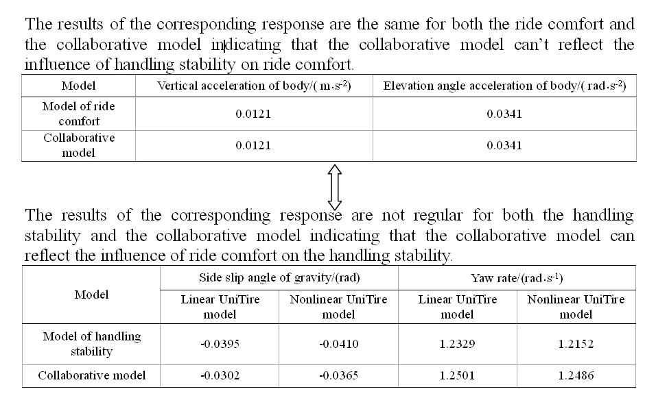
- A collaborative model for ride comfort and handing stability is built by adopting state equations
- The handling stability model has no effect on the ride comfort model
- The parameters obtained by the handling stability and the collaborative model don’t show certain regularity
1. Introduction
With the development of society, cars have become an indispensable part of people’s lives. The demand for vehicle comfort is constantly increasing, and vehicle ride comfort, in particular, has become the focus of research on vehicle dynamics [1]. Safety, ride comfort and economy are the major factors for making any successful transportation business [2]. In the vehicle dynamics sphere, most researches concentrate around improving ride comfort, handling capability and safety for vehicles having the four-wheel configuration [3]. In the current scenario, improvements of driving safety and comfort are very lasting subjects in the vehicle design. It is not only a need, but also as a challenge for engineers to develop the best quality of vehicle in order to attain the superior performance [4]. So, the objective assessment of automotive ride comfort is important for the vehicle development [5].
Ride comfort and handling stability are two important properties of the vehicle. In the past, most of researches were focused on the ride comfort or steering stability respectively ignoring the connection and interaction between these two properties. In order to carry out a coordinated research on ride comfort and handling stability, a reasonable technical route should be chosen firstly [6].
Experimental research and virtual prototype technology can check the theoretical analysis results and discover research demerits. But the experiment disadvantage is its high cost and long cycle. Theoretical analysis uses mass, damping, stiffness and geometric parameters to describe the actual components establishing mechanics, mathematics and simulation models using laws and theorems. With this method, the degree of freedom can be reasonably set, the workload determined by the parameters is small, the solution is rapid, and the effect is satisfactory.
There is a connection between the ride comfort and handling stability through tires. When a vehicle is driving on an uneven road surface, it will cause the vertical load of tires to change, resulting in a change in the cornering force of the tire affecting the steering stability [7].
The related problem has been studied in the literatures. A brief review is presented in what follows.
Choi et al. [8] performed progressive sequential approximate optimization based on a meta-model to solve the problem of generated side load in a MacPherson strut suspension in order to improve riding comfort. Navid et al. [9] used the computational Multibody System (MBS) approach and developed a 3D passive Human Biomechanical Model (HBM) for a seated human to improve ride comfort. Du [6] proposed a method and developed vertical and horizontal weighting filters to design weighting filters according to the frequency weighting factors, and made good use of the additional evaluation method of automotive ride comfort. Gong et al. [10] proposed a new passive control method to suppress vertical flexural vibration of a railway vehicle car body by mounting dampers on the longitudinal beams of the car body under frame. Guo and Zhang [3] established different types of vehicle models with different degrees of freedom (DOFs) that used different types of numerical methods. Hemanth et al. [11] presented a ride comfort and road holding analysis of passive and semi-active suspension system using a quarter car model. Liang et al. [12] proposed a three-dimensional train-track model to capture the flexible vibration features of high-speed train carriages based on the flexible multi-body dynamics approach. The flexible car-body is modeled using both the finite element method (FEM) and the multi-body dynamics (MBD) approach. Javanshir et al. [13] modeled a dependent suspension system mostly used in off-road vehicles using Trucksim software. Then, geometric parameters of suspension system were optimized using the integrated anti-roll bar and coiling spring so that ride comfort, handling and stability of vehicle were improved. Alfadhli et al. [14] presented a novel, simple and reliable control strategy for an active seat suspension, intended for use in a vehicle, which attenuates the harmful low-frequency vertical vibration at the driver’s seat. Khodadadi and Ghadiri [15] used the Proportional Integral Derivative (PID), fuzzy logic and H∞ controllers to control the car suspension system based on the half car model and developed a self-tuning PID controller based on the fuzzy logic to improve the performance of the system. Kumar et al. [16] proposed a self-tuned robust fractional order fuzzy proportional derivative (FO-FPD) controller for a nonlinear active suspension system of a quarter car. Liang et al. [17] developed a technique of optimal vibration control and simulation for vehicle active suspension systems and established a mechanical model and nonlinear dynamic system for a class of tracked vehicle half-car suspensions vibration control considered the nonlinear damping of springs. Durukan Bedük et al. [18] analyzed the interaction between the damper characteristics and vehicle ride response by using a detailed mathematical damper model together with a verified full vehicle simulation model. Haiyan et al. [19] proposed a hierarchical integrated controller for the distributed electric vehicle to improve the driving safety, handling stability, ride comfort, and road tracking capabilities. Huihui et al. [20] investigated the energy-efficiency design of adaptive control for active suspension systems with a bio-inspired nonlinearity approach.
In the literature reviewed, most researchers have not studied the ride comfort and handling stability collaboratively. Most of the multi-DOF vehicle models were simplified. Some models ignored the effect of kinematic changes toward the tire. Most researchers have focused on the linear model. A small number used a parametric model that coupled with kinematic profiles to simulate the effect of suspension kinematics. A small number of researchers have focused on the nonlinear model, and they have usually neglected the effect on solving methods from dynamic simulation and low-amplitude vibration ride comfort, such as from vibration transmitted from the road.
In the paper, based on the UniTire model, the road surface roughness is considered to research the ride comfort and handling stability collaboratively. The theoretical analysis method is used to establish a synergistic model with general significance. An algorithm for executing co-simulation for ride comfort and handling stability is proposed. The proposed algorithm can overcome the limitation of separate research and can also help to understand the relationship between these two properties well, providing new research ideas for the optimization of automotive performance and dynamics control.
2. Model of tire and road surface
2.1. UniTire model
The lateral force expression of the UniTire model is:
where, Fyi is the lateral force; ˉFyi is the dimensionless lateral force; μyi is the lateral friction factor; Fzi is the vertical tire load; ϕi is the dimensionless lateral slip ratio; kyi is the tire cornering stiffness of the tire; αi is the tire slip angle; Fzni is the dimensionless vertical load; Fz0 is the rated tire load; s1-s8 is the lateral characteristic parameters of the UniTire model under single condition; mi and ni are the intermediate parameters.
The UniTire model is a nonlinear model that degenerates into a linear model when the lateral force expression is:
2.2. Road surface model with filtered white noise
The mathematical model is:
where a is the pavement constant of the road roughness; uis the speed; W(t) is the standard Gaussian white noise which mean value and variance are 0 and 1 satisfying:
where σ2 is the variance of the road roughness; δ(t-τ) is the function for δ.
It is assumed that the road surface roughness model of front wheels according to Eq. (10) is:
It is set that the distance between the contact point of the rear and the front wheels is l2. Then the time delay of the rear wheel relative to the front wheel is Δ2=l2/u. Such a pure time delay system is approximated using the Pade. The transfer function relationship between the front and rear point excitation input using a first-order algorithm is expressed as:
where q1(s) and q2(s) are the Laplace transform of q1(t) and q2(t); s is the Laplace operator. Eq. (14) can be obtained by Laplace inverse transformation for Eq. (13) as:
Therefore, the state equation of the front and rear wheel excitation can be expressed as:
3. Plane model of ride comfort and handling stability
3.1. 4-DOF ride comfort model
A vehicle is a complex vibration system with multiple masses. It is generally considered to have 18 degrees of freedom. Therefore, it is quite complicated to study actual vibration of the car, and it is difficult to achieve the intended purpose. Therefore, it is assumed that:
(1) The car body is treated as a rigid body with concentrated mass, only considering the influence of vertical and pitching vibration of the car body on the ride comfort. And also, the front and rear vibration as well as the lateral vibration of the car body is ignored.
(2) It is assumed that the car body vibrates near the equilibrium position slightly. And the stiffness and damping of the suspension are considered as a constant.
(3) The vehicle is symmetrical along the longitudinal centerline and makes a uniform linear motion.
(4) The pavement is a normal, stochastic process of steady state and isotropy.
(5) Other sources other than the road surface is ignored.
The simplified 4-DOF planar model is shown in Fig. 1.
Fig. 14-DOF vehicle vibration model
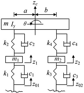
In Fig. 1 m1 and m2 are masses of the front and rear wheels; m is the body mass; Iy is the moment of inertia around the y axis; k1 and k3 are the synthesized stiffness of front and rear tires; c1 and c3 are the equivalent damping coefficients of the front and rear tires; k2 and k4 are the stiffness of the front and rear suspensions; c2 and c4 are the equivalent damping coefficients of the front and rear suspensions; z01 and z02 are the displacement excitation of the road affecting on the front and rear tires in the vertical direction; z1 and z2are the displacement of the front and rear wheels in the vertical direction; zc is the displacement of the body mass in the vertical direction; θ is the elevation angle displacement of the body; a and b are the distances of front and rear axles from the center of gravity.
The vibration equation of the vehicle can be obtained according to the Lagrange equation:
where M is the mass matrix of the vehicle; C is the damping matrix of the vehicle; K is the stiffness matrix of the vehicle; Z is the displacement vector corresponding to the vehicle’s respective degrees; Q is the pavement input vector; Kt is the stiffness matrix of the tire; Ct is the damping matrix of the tire:
Kt=[0000k100k3],Ct=[0000c100c3],
T=[k2+k4-ak2+bk4-k2-k4-ak2+bk4a2k2+b2k4ak2-bk4-k2ak2k2+k10-k4-bk40k3+k4],
S=[c2+c4-ac2+bc4-c2-c4-ac2+bc4a2c2+b2c4ac2-bc4-c2ac2c2+c10-c4-bc40c4+c3].
The dynamic deflection of the front and rear suspensions are described as:
The static loads of the front and rear tires are:
The dynamic loads of the front and rear tires are:
3.2. 2-DOF handling stability model
It is assumed that the vehicle travels on an uneven road and the vehicle is simplified to a 2-DOF planar model. In the state space form, it is:
where β is the side slip angle of the gravity, ωr is the yaw rate of the vehicle, m is the vehicle mass, Iz is the moment of inertia around the z axis, α1 and α2 are side slip angles of the front and rear tires, Fy1 and Fy2 are the lateral forces of the front and rear tires, δ is the front steering angle.
α1 and α2 can be expressed as:
The vertical loads of the front and rear axles are:
The centroid lateral acceleration of the vehicle is:
4. Collaborative model of ride comfort and handing stability
4.1. State equation of road surface
It is set that Q=[˙q1(t)˙q2(t)] then Eq. (15) can be described as:
where:
4.2. State equation of ride comfort
Eq. (25) can be obtained multiplied by M-1 to Eq. (16):
It is set that A=-M-1C, B=-M-1K, I1=M-1Kt, I2=M-1Ct, Y=[Z˙Z]T then Eq. (17) can be converted to the following state equation:
where:
4.3. State equation of the handing stability
It is set that x2=[β,ωr]T then:
where:
4.4. Collaborative model of ride comfort and handing stability
It is set that x1=[Y,Q]T then:
where:
It is set that x=[x1,x2]Tthen:
where:
For the sake of simplicity, it is necessary to introduce the following representation: β=x(11), ωr=x(12), q1=x(1), q2=x(2), z1=x(3), z2=x(4).
5. Co-simulation algorithm
The collaborative model of the ride comfort and handling stability is solved by Eq. (29) and the UniTire model in the time domain to obtain the response sequence of ride comfort and handling stability. The specific simulation algorithm is as follows:
(1) The total simulation time and the sampling time are set as T and Δt, solving the number of discrete points N=T/Δt+1 and discrete time points ti=i×Δt, i= 0, 1, 2, …, N. When i= 0, it is set {x(0)}= 0.
(2) K, P and R are calculated according to Eq. (29).
(3) N Gaussian white noise sequence W(i), i= 1, 2, …, N of discrete points is obtained.
(4) Fz1(i) and Fz2(i), i= 1, 2, …, N are solved according to Eq. (18), Eq. (19) and Eq. (22).
(5) α1(i) and α2(i), i= 1, 2, …, N are calculated with given δ according to Eq. (21).
(6) Fzn1(i), Fzn2(i), E11(i), E12(i), ky1(i), ky2(i), μy1(i), μy2(i), m1(i), m2(i), n1(i), n2(i), ϕ1(i), ϕ2(i), ˉFy1(i) and ˉFy2(i), i= 1, 2, …, N are solved according to Eqs. (1)-(7) for nonlinear UniTire model. ky1(i), ky2(i), Fy1(i) and Fy2(i), i= 1, 2, …, N are solved according to Eqs. (8), (9) for the linear UniTire model.
(7) {x(i)}, i= 1, 2, …, N are obtained by solving Eq. (29) using the 4th-order Runge-Kutta method.
(8) Obtaining the response sequence of the collaborative mode according to {x(i)}.
5.1. Result of the Co-simulation
The results of the co-simulation are calculated with the B-level and C-level road surface according to the parameters of the real vehicle shown in Table 1. The vehicle speed and the front wheel angle are set as u= 60 km/h, δ= 0.1 rad. And the solution is calculated by MATLAB software in computer which CPU is 2.8 GHz/Pentium IV and the operating system is Window XP.
Table 1Simulation parameters
Parameter | Symbol | Value | Unit |
Body mass | m | 920 | kg |
Front wheel mass | m1 | 50 | kg |
Rear wheel mass | m2 | 50 | kg |
Yaw moment of inertia around the y axis | Iy | 948 | kg·m2 |
Distance of center of gravity to front axle | a | 1.101 | m |
Distance of center of gravity to rear axle | b | 1.091 | m |
Synthesized stiffness of front tire | k1 | 294 | kN/m |
Synthesized stiffness of rear tire | k3 | 294 | kN/m |
Stiffness of front suspension | k2 | 33.4 | kN/m |
Stiffness of rear suspension | k4 | 42.2 | kN/m |
Equivalent damping coefficient of front suspension | c2 | 3340 | N·s/m |
Equivalent damping coefficient of rear suspension | c4 | 2845 | N·s/m |
Equivalent damping coefficient of front tire | c1 | 80 | N·s/m |
Equivalent damping coefficient of rear tire | c3 | 80 | N·s/m |
Vehicle speed | u | 80 | km/h |
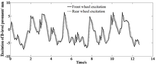
The results of the front and rear wheel excitation of B-level and C-level road surface are shown in Figs. 2, 3. It is can be seen from Figs. 2, 3 that the simulation curve of the rear wheel has a delay in time to the front one. This is because the distance of the center of gravity to the rear axle is smaller than that of the front one. And also figures demonstrate that the amplitude of the C-level road surface is bigger than that of the B-level road surface indicating that C-level road surface has bigger road roughness coefficient.
Fig. 2Front and rear wheel excitation of B-level pavement
The simulation results of the ride comfort are shown in Fig. 4. The figures indicate that these results can be analyzed for ride comfort, suspension layout and driving safety. Moreover, these vibrational responses do not vary with the tire model. At the same time, the analysis for the vertical acceleration and elevation angle acceleration of the body has laid a good foundation for studying the ride comfort and handling stability of the vehicle.
Fig. 3Front and rear wheel excitation of C-level pavement
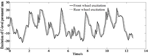
Fig. 4Simulation results of ride comfort
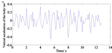
a) Vertical acceleration of B-level pavement
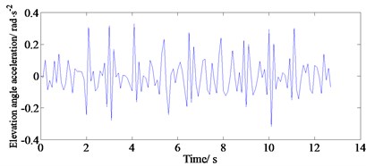
b) Elevation angle acceleration of B-level pavement body
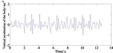
c) Vertical acceleration of C-level pavement body
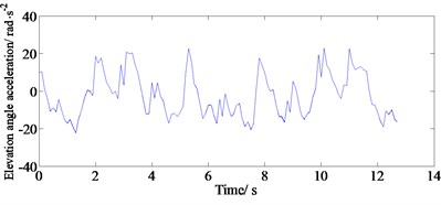
d) Elevation angle acceleration of C-level pavement body
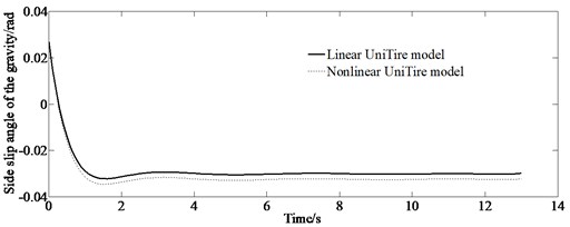
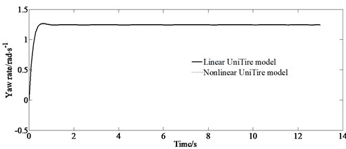
The simulation results of the handling stability are shown in Fig. 5. It can be seen from Fig. 5 that the responses of the vertical acceleration and elevation angle acceleration of the body have a certain degree of fluctuation indicating the effect of road surface roughness on the handling stability through the collaborative model. From the figures, it is also shown that the simulation curves are different between the linear and nonlinear UniTire models. It is obvious that both the side slip angle of the gravity and yaw rate obtained by the linear tire model simulation are larger than those of the nonlinear tire model indicating that the linear UniTire model is conservative for a research of the handling stability.
Table 2Response comparison of ride comfort model and collaborative model
Model | Vertical acceleration of body / (m·s-2) | Elevation angle acceleration of body / (rad·s-2) |
Model of ride comfort | 0.0121 | 0.0341 |
Collaborative model | 0.0121 | 0.0341 |
A comparison of the collaborative model with a separate ride comfort model and separate handling stability model is shown in Tables 2, 3. It can be seen from Table 2 that the vertical acceleration and the elevation angle acceleration of the body are the same between the collaborative model and the ride comfort model, indicating that the handling stability model has no effect on the ride comfort model.
It can be seen from Table 3 that the side slip angle of the gravity and the yaw rate are different between the collaborative model and the handling stability model. But the simulation results in the regard to these two parameters obtained by the two models do not show certain regularity.
Table 3Response comparison of handling stability model and collaborative model
Model | Side slip angle of gravity / (rad) | Yaw rate / (rad·s-1) | ||
Linear UniTire model | Nonlinear UniTire model | Linear UniTire model | Nonlinear UniTire model | |
Model of handling stability | –0.0395 | –0.0410 | 1.2329 | 1.2152 |
Collaborative model | –0.0302 | –0.0365 | 1.2501 | 1.2486 |
Fig. 5Simulation results of handling stability
a) Side slip angle of gravity
b) Yaw rate
5.2. Experimental result
Real vehicle test is carried out to verify the correctness of the simulation results of the handling stability and the ride comfort of C-level pavement.
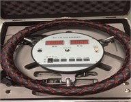
The block diagram of test system for the handling stability is shown in Fig. 6. And the main measurement devices are shown in Figs. 7, 8.
Fig. 6Block diagram of test system
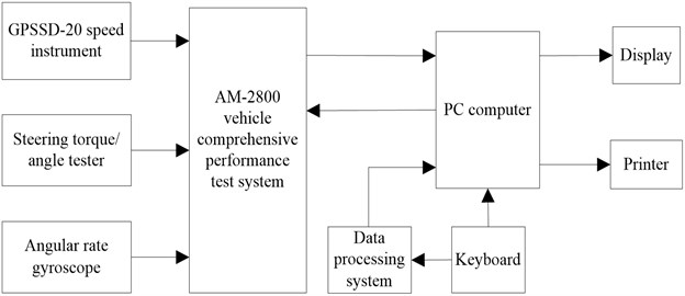
Fig. 7Measurement devices

a) GPSSD-20 speed instrument
b) Steering torque/angle tester
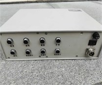
c) AM-2800 vehicle comprehensive performance test system
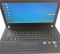
d) Lenovo computer
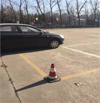
Fig. 8Real test vehicle
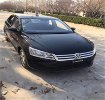
a)
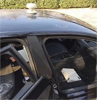
b)
c)
The test procedure is in accordance with ISO/TR3888-2004.
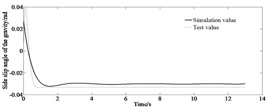
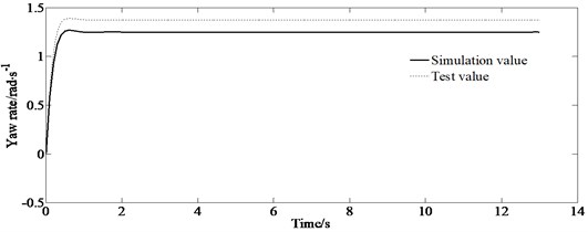
The experimental results of the handling stability are shown in Fig. 9.
Fig. 9Experimental results of handling stability
a) Side slip angle of gravity
b) Yaw rate
Fig. 9 shows that the test value is bigger than the corresponding simulation value which indicates at larger driver’s busyness to maneuver the vehicle. However, the trend of the simulation values is similar to the experimental values, verifying the correctness of the simulation results.
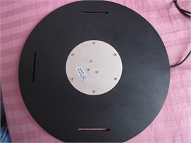
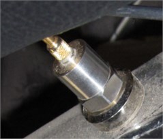
In the test of the ride comfort, a three-direction acceleration sensor (PCB-480B21, made in the USA) and a piezoelectric acceleration sensor are installed at the driver’s seat and above the right front wheel of the vehicle correspondingly as shown in Figs. 10(a), (b).
Fig. 10Measurement equipment for verification of ride comfort
a) Three-direction acceleration sensor
b) Piezoelectric acceleration sensor
The test procedure in accordance with ISO2631-1-1997 is as follows:
Step 1: Putting the bump in the middle of the experimental road and adjusting the distance between two bumps according to the vehicle wheel track. In order to ensure that the left and right wheels of the vehicle pass through the bumps at the same time, the two bumps should be put on a line perpendicular to the traveling direction of the vehicle.
Step 2: The vehicle speed should be stabilized at 50 m before the bumps. Then the vehicle passes over the bumps at a constant speed. Recording begins when the front wheel of the vehicle approaches the bump, and stops after the vehicle passes over the bumps and the impact response disappears.
Step 3: Repeating Step 2 process 6 times.
Fig. 11Experimental results of ride comfort
a) Vertical acceleration of C-level pavement body
b) Elevation angle acceleration of C-level pavement body
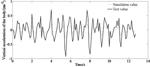
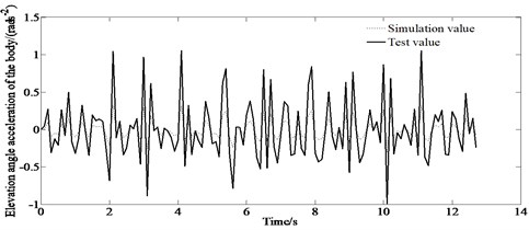
The experimental results of the ride comfort are shown in Fig. 11. Fig. 11 demonstrates that there are discrepancies between the simulation value and the experimental value. This is because of the existing difference between the pavement model and the actual road surface as well as the difference from the real vehicle with a simplified model. However, the simulation value is consistent with the experimental value. So, the results can verify the correctness of the proposed method.
6. Conclusions
Based on the UniTire model, considering the road surface roughness, a 4-DOF ride comfort model, and a 2-DOF handling stability model as well as the collaborative model which is established by uniting the above two models through the state equation are proposed. And the corresponding co-simulation algorithm is given. Then the co-simulation of the ride comfort and handling stability of a vehicle under uneven road surface is carried out. The results show that the corresponding values of both the side slip angle of the gravity and the yaw rate obtained by the linear tire model simulation are larger than those of the nonlinear tire model for the handling stability. And the results of the corresponding response are the same for both the ride comfort and the collaborative model. However, the results of the corresponding responses are different for the handling stability and the collaborative model. And these two parameters obtained by simulation of these two models are not regular. The results indicating that the collaborative model can reflect the influence of ride comfort on the handling stability, but cannot reflect the influence of handling stability on ride comfort. This is mainly because the handling stability model does not have the coupled mechanical parameter with the ride comfort model. Therefore, it is necessary to establish a spatial collaborative model to reflect the relationship between the ride comfort and the handling stability comprehensively.
References
-
Guo P., Zhang J. H. Metrical model and multi-objective optimization analysis of vehicle vibration. Journal of Zhejiang University-Science A (Applied Physics and Engineering), Vol. 18, Issue 5, 2017, p. 393-412.
-
Gangadharan K. V., Chandramohan S. Analytical studies on ride quality and ride comfort in chennai mass rapid transit system (MRTS) railroad vehicle. Journal of The Institution of Engineers (India): Series C, Vol. 99, Issue 6, 2018, p. 737-742.
-
Youn I., Khan M. A., Uddin N., Youn E., Tomizuka M. Road disturbance estimation for optimal preview control of active suspension systems based on tracked vehicle model. International Journal of Automotive Technology, Vol. 18, Issue 2, 2017, p. 307-316.
-
Hemanth K., Hemantha Kumar, Gangadharan K. V. Vertical dynamic analysis of quarter car suspension system with MR damper. Journal of the Brazilian Society of Mechanical Sciences and Engineering, Vol. 39, 2017, p. 41-51.
-
Du F. Frequency weighting filter design for automotive ride comfort evaluation. Chinese Journal of Mechanical Engineering, Vol. 29, Issue 4, 2016, p. 727-738.
-
Li J., Wang W. Z., Zhao Q., Zhang C. X. Random vibration analysis of military vehicle based on pseudo-excitation method. Automotive Engineering, Vol. 38, Issue 3, 2016, p. 368-372.
-
Huanming C., Konghui G. Simulation of the effects of tire performance on vehicle handling stability. Automotive Engineering, Vol. 37, 2015, p. 491-495.
-
Choi B. C., Cho S., Kim C. W. Sequential approximate optimization of Macpherson strut suspension for minimizing side load by using progressive meta-model method. International Journal of Automotive Technology, Vol. 19, Issue 3, 2018, p. 455-461.
-
Navid M., Hamid A., Saeid N., Kyle N. Directional and sectional ride comfort estimation using an integrated human biomechanical-seat foam model. Journal of Sound and Vibration, Vol. 403, 2017, p. 38-58.
-
Gong D., Zhou J., Sun W. Passive control of railway vehicle car body flexural vibration by means of under frame dampers. Journal of Mechanical Science and Technology, Vol. 31, Issue 2, 2017, p. 555-564.
-
Hemanth K., Kumar1 H., Gangadharan K. V. Vertical dynamic analysis of quarter car suspension system with MR damper. Journal of Brazilian Society of Mechanical Sciences and Engineering, Vol. 39, 2017, p. 41-51.
-
Liang L., Qing Z., Xinbiao X., et al. Integration of car-body flexibility into train-track coupling system dynamics analysis. Vehicle System Dynamics, Vol. 56, Issue 4, 2018, p. 485-505.
-
Javanshir I., Maseleno A., Tasoujian S., Oveisi M. Optimization of suspension system of heavy off-road vehicle for stability enhancement using integrated anti-roll bar and coiling spring mechanism. Journal of Central South University of Technology, Vol. 25, 2018, p. 2289-2298.
-
Alfadhli A., Darling J., Hillis A. J. Control of active seat with vehicle suspension preview information. Journal of Vibration and Control, Vol. 24, Issue 8, 2018, p. 1412-26.
-
Khodadadi H., Ghadiri H. Self-tuning PID controller design using fuzzy logic for half car active suspension system. International Journal of Dynamics and Control, Vol. 6, 2018, p. 224-232.
-
Kumar V., Rana K. P. S., Kumar J., Mishra P. Self-tuned robust fractional order fuzzy PD controller for uncertain and nonlinear active suspension system. Neural Computing and Applications, Vol. 30, 2018, p. 1827-1843.
-
Liang Y. J., Li N., Gao D. X., Wang Z. S. Optimal vibration control for nonlinear systems of tracked vehicle half-car suspensions. International Journal of Control, Automation and Systems, Vol. 15, Issue 4, 2017, p. 1675-1683.
-
Bedük Durukan M., Çalışkan Kemal, Henze Roman Advanced parameter analysis for damper influence on ride dynamics. Journal of Vibration and Control, Vol. 24, Issue 8, 2018, p. 1393-411.
-
Haiyan Z., Weixuan C., Jinyang Z., Yilin Z., Hong C. Modular integrated longitudinal, lateral, and vertical vehicle stability control for distributed electric vehicles. IEEE Transactions on Vehicular Technology, Vol. 68, Issue 2, 2019, p. 1327-1338.
-
Huihui P., Xingjian J., Weichao S., Huijun G. Bio-inspired dynamics-based adaptive tracking control for nonlinear suspension systems. IEEE Transactions on Control Systems Technology, Vol. 26, Issue 3, 2018, p. 903-914.
About this article
This paper was supported by the Science and Technology Program Foundation of Weifang under Grant 2015GX007 and the Foundation Research Funds for the Central Universities under Grant 3122016A004. The first author gratefully acknowledges the support agency.

