Abstract
The removal of unwanted gas bubbles is an important operation in many processes. In this paper, the mechanism of the degassing of highly viscous fluids by low-frequency vibration is studied numerically using the computational fluid dynamics (CFD). The effects of vibration frequency and amplitude on the degassing rate are investigated. The results show that the superimposed mechanical vibration largely affects the degassing rate of shear-thinning fluids but exerts no effect on that of Newtonian fluids. The de-gassing rate of shear-thinning fluids depends on the vibration frequency and amplitude. What’s more, low-frequency and small-amplitude vibration is particularly useful in re-moving gas bubbles from viscous shear-thinning fluids, however, high-frequency or large-amplitude vibration may intensify air entrapment and brings new gas bubbles into fluids.
1. Introduction
Formation of gas bubbles is normal and practically inevitable when fluids, especially highly viscous fluids, are agitated or flow in open containers [1]. Considering that the unwanted gas bubbles will damage the product quality, degassing operation is widely carried out to remove gas bubbles from highly viscous liquids in the fields of chemical industry, food, metallurgy and textile, etc. [2, 3] However, when pushed up by buoyancy only, gas bubbles in highly viscous fluids are very difficult to be removed because of large drag resistance.
The degassing by low-frequency vibration (LFVD) is a possible way to alleviate these drawbacks. Harold et al. [4] proposed a typical low frequency vibration system for degassing at about 10 Hz to 100 Hz, in which the container was vibrated vertically on a shaker platform. However, improper vibration cannot remove gas bubbles, and even generates new gas bubbles in fluids. Blekhman et al. [5] observed the suction of gas bubbles into the container and the ascent of matters which were heavier than the liquid in a container under vibration. Therefore, it is important to study the possibility and mechanism of applying low-frequency vibration to remove gas bubbles from highly viscous fluids.
This paper is aimed to explore the possibility of applying low-frequency vibration to remove free gas bubbles from highly viscous fluids. The two-dimensional VOF method is used to simulate the motion of gas bubbles in highly viscous fluids, in which the continuum surface force (CSF) model is used to account for the surface tension effects. The effects of vibration frequency and amplitude on the degassing rate are systematically investigated. The benefits and limits of LFVD are outlined.
2. Governing equations and computational method
2.1. Physical model and materials
The physical model of vibration degassing is presented in Fig. 1. A rigid cylindrical container, with a diameter of D=100 mm and a height of H=100 mm, is filled with liquid and air. The height of liquid is 80 mm and the remainder is air.
Fig. 1The physical model of vibration degassing
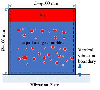
The container is fixed on the vibration plate. A sinusoidal vibrational movement is imposed on the container in the Y direction, and the displacement of the container y is described by Eq. (1) below:
where A is the vibration amplitude, t is time, and f is the vibration frequency (Hz). The vibration velocity of the container u is obtained by differentiating Eq. (1) with respect to time, thus:
For the rheological models studied here, the apparent viscosity function for a temperature-independent fluid takes the following form [6]:
where ˙γ is the shear rate, k is the flow consistency index and n is the power law-index; n< 1 for the shear-thinning fluids, and n= 1 for the Newtonian fluids. In this study, the carboxymethyl cellulose solution (CMC) is taken as the primary phase and the air as the secondary phase. Their physical properties are given in Table 1 [7].
For LVFD, over the full range of vibration frequency and amplitude used (f≤100 Hz and A≤5 mm), the vibration Reynolds number Rev=ρAωD/μ is always smaller than 500, so the flow remains laminar [8].
Table 1Physical properties of gas and liquid phases in simulations
Material | Density ρ [kg m-3] | Viscosityη [Pa s] | Surface tension [N m-1] | |
k (Pa sn) | n | |||
CMC | 1000.0 | 1.47 | 0.57 | 0.0717 |
Air | 1.225 | 1.789×10⁻⁵ | 1 | / |
2.2. Numerical simulation procedures
The general assumption for the model is that the flow is laminar, incompressible and isothermal. The dynamic stress balance is realized through the CSF model, which is incorporated in the momentum equation by introducing a volume force as described by Brackbill et al. [9]. In order to improve the calculation efficiency, a two-dimensional numerical transient model is applied. A gas bubble with a diameter of 2 mm is used to simplify the calculations, while bubble breakup and coalescence are ignored. The bottom and side of the container are defined as the moving walls with no-slip boundary condition, so their velocities are described as a function of time. For this purpose, the dynamic mesh approach (laying technique), which is used to simulate flows when the shape of the fluid domain changes with time due to the motion of the boundary, is applied to the walls of the present numerical model. The interface at the top of the container is defined as the pressure outlet.
A preliminary grid convergence study is carried out to verify whether the solution is grid independent. The bubble rising velocity shall change by not more than 2.0 % along with the growing number of grids. Finally, a mesh size of 0.5 mm is selected and 40,000 quadrilateral cells constitute the whole fluid domain.
The processes are numerically solved using ANSYS Fluent. A combination of the VOF model and the laminar model is used to describe this process. The iteration time step, which is usually 0.0002 s or smaller, is determined by the vibration frequency and the increased resolution is found to have no significant effect on the predicted flow field.
3. Results and discussions
3.1. Mechanism of vibration degassing
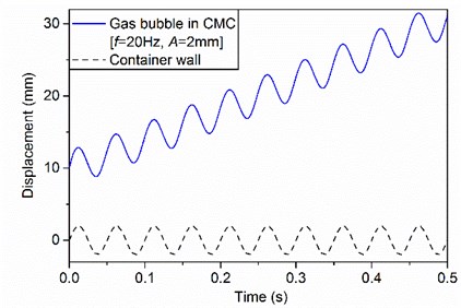
At the beginning of simulation, a gas bubble is imposed at the center and 10 mm above the bottom of the domain. Without vibration, the gas bubble rises vertically from the initial position to the liquid surface. When the container is vibrated vertically, the location of the gas bubble on the centerline becomes unstable and the gas bubble rises along with the vertical vibration at the same frequency. Fig. 2 shows an example for the displacements of the container wall and the gas bubble obtained from CFD.
Fig. 2The displacements of container wall and gas bubble
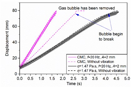
The degassing rate of CMC is significantly improved in LFVD (see Fig. 3). However, the degassing rate of Newtonian fluids is unaffected by the mechanical vibration imposed on the container wall, which is identical to that of the steady-state rectilinear flow irrespective of vibration amplitude and frequency [8]. This is confirmed on glycerol, a well-known Newtonian fluid, in the vibration frequency range of 0-100 Hz and the vibration amplitude range of 0-4 mm.
The shear thinning seems to be the possible reason for the degassing enhancement observed. The additional shear brought by vibration increases the gas bubble rising velocity, which is reflected as a decrease of apparent viscosity below the viscosity of fluids without vibration. Thus, the superimposition of vibration on the container wall leads to an increase of the degassing rate above the natural degassing rate. As is shown in Fig. 3, the results agree with the physical interpretation, that is, the viscosity is minimal and the degassing rate is maximal when the shear rate is maximal, and vice versa.
Fig. 3Comparison of natural degassing and vibration degassing
3.2. Effects of vibration parameters
The vibration frequency and amplitude vary within the ranges of f= 0-100 Hz and A= 0-5 mm, respectively. The other parameters are fixed throughout the simulations so that the resulting effects are attributed to the variations of vibration parameters only. The total time of natural degassing tn (without vibration) and vibration degassing tv is used to calculate the degassing enhancement ratio E, which is defined as follows:
In comparison with natural degassing, a positive increase of the degassing rate is obtained under low-frequency vibration in the range of 0-90 Hz on the whole (E> 0). Fig. 4 shows the variations of the degassing enhancement ratio as a function of vibration frequency in the range of 0-90 Hz. A sharp increase of the degassing enhancement ratio can be observed in the vibration frequency range of 0-40 Hz. This is because the increase of vibration frequency leads to the increase of the shear rate, which reduces the local apparent viscosity and thus improves the degassing rate.
Fig. 4Effects of vibration frequency on degassing enhancement ratio and aspect ratio
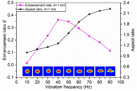
However, the degassing enhancement ratio decreases gradually when the vibration frequency is larger than 40 Hz. It seems that the degassing rate is not significantly enhanced under high-frequency vibration. The reason becomes clear when the gas bubble shape is monitored. The aspect ratio, which refers to its width-to-height ratio, is used to assess the change of gas bubble shape. Fig. 4 shows the aspect ratios and the shapes of gas bubbles which rise to the middle of container at different vibration frequencies. The gas bubble becomes elliptical and even flat along with the increase of vibration frequency. The change of gas bubble shape increases the rising resistance and decreases the rising velocity. Thus, it is very important to select the appropriate vibration frequency for degassing.
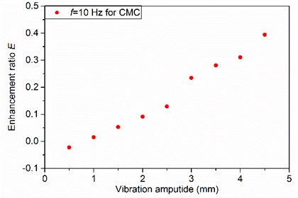
Fig. 5 shows that the degassing enhancement ratio is increased monotonically over the full range of vibration amplitude studied. This is because the increment of vibration amplitude increases the shear rate, which reduces the local apparent viscosity and thus improves the degassing rate. At the same time, the effects of the gas bubble shape on the rising velocity are weaker than those of the increasing vibration amplitude. As a result, the degassing rate increases monotonically with the vibration amplitude in the range studied.
Fig. 5Effects of vibration amplitude on degassing enhancement ratio
3.3. Feasible region of degassing
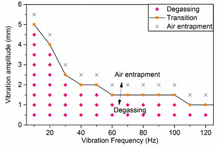
High vibration intensity will improve the degassing rate. However, as the vibration intensity further increases, the free surface is distorted or broken up into bubbles and droplets, which intensifies air entrapment and brings some new gas bubbles under the free surface. The phenomenon is helpful for mixing and mass transfer but not desired in degassing process. Similar problems have been analysed in many publications [5].
The feasible region of degassing is plotted with vibration frequency and amplitude in Fig. 6. The diamond symbols indicate the vibration parameters for feasible degassing, that is, no new gas bubbles will be brought into the fluids from the free surface. The cross symbols indicate the conditions where air entrapment occurs. The square symbols indicate a transition between air entrapment and degassing, where gas bubbles are formed randomly below the free surface but then quickly rise to the free surface.
Fig. 6The feasible region of vibration degassing plotted with vibration frequency and amplitude of CMC
4. Conclusions
The effectiveness of applying low-frequency vibration for the removal of gas bubbles from highly viscous fluids is investigated through a CFD model in this paper. The results show that vibration can be an efficient process to degas highly viscous shear-thinning fluids, but vibration degassing has no effect on the Newtonian fluids. The enhancement of degassing rate is attributed to the change of apparent viscosity imparted by the additional shear applied. The degassing rate of shear-thinning fluids is affected by both vibration frequency and amplitude, and low-frequency and small-amplitude vibration is particularly useful in removing gas bubbles from shear-thinning fluids. LFVD method enjoys great advantages, which neither requires intrusive devices, nor limits the structures or shapes of containers, and thus will find wide applications in laboratory and industrial fields.
References
-
Kizito J., Balasubramaniam R., Nahra H., Agui J., Troung D. Vapor-gas bubble evolution and growth in extremely viscous fluids under vacuum. 47th AIAA Aerospace Sciences Meeting Including the New Horizons Forum and Aerospace Exposition, Florida, 2009, p. 1147-1158.
-
Alimi A., Lübke M., Wünsch O. Modelling and simulation of degassing process. PAMM, Vol. 14, Issue 1, 2014, p. 593-594.
-
Yu S., Louhenkilpi S. Numerical simulation of dehydrogenation of liquid steel in the vacuum tank degasser. Metallurgical and Materials Transactions B-Process Metallurgy and Materials Processing Science, Vol. 44, Issue 2, 2013, p. 459-468.
-
Howe H. W., Warriner J. J., Cook A. M., Coguill S. L., Farrar L. C. Apparatus and Method for Resonant-Vibratory Mixing. US 10/766,558, 2007.
-
Blekhman I. I., Blekhman L. I., Sorokin V. S., Vaisberg L. A., Vasilkov V. B., Yakimova K. S. Motion of gas bubbles and rigid particles in vibrating fluid-filled volumes. Procedia Iutam, Vol. 8, 2013, p. 43-50.
-
Eesa M., Barigou M. Enhancing radial temperature uniformity and boundary layer development in viscous Newtonian and non-Newtonian flow by transverse oscillations: a CFD study. Chemical Engineering Science, Vol. 65, Issue 6, 2010, p. 2199-2212.
-
Lakota A. Effect of highly viscous non-Newtonian liquids on gas holdup in a concurrent upflow bubble column. Acta Chimica Slovenica, Vol. 54, Issue 4, 2007, p. 678-687.
-
Tian S., Barigou M. An improved vibration technique for enhancing temperature uniformity and heat transfer in viscous fluid flow. Chemical Engineering Science, Vol. 123, 2015, p. 609-619.
-
Brackbill J. U., Kothe D. B., Zemach C. A continuum method for modeling surface tension. Journal of Computational Physics, Vol. 100, Issue 2, 1992, p. 335-354.
About this article
This project is supported by National Natural Science Foundation of China (Grant No. 51605179) and China Postdoctoral Science Foundation (Grant No. 2017M612445).

