Abstract
In the article is implemented interresonance mechanical oscillating system vibrational technological equipment, which provides using two continuous of connected area successively to working body vibrational machines. Disturbance of the structure is carried out by applying a variable-sign power supply voltage to the reactive continuous section, where in interaction with the magnetic field from the permanent magnets, a variable-sign disturbance force occurs. Inertial forces from the reactive continuous section are transferred to the intermediate continuous section, which resonates with the working body. In fact, an interresonance discrete-continuous oscillating system is obtained in which there are no springs. The function of springs is performed by bodies with distributed parameters that have elastic properties. Based on the Krylov-Duncan functions, a system of equations was formed that establishes the amplitude of oscillations of the working body. The amplitude-frequency characteristic of the discrete-continuous system was studied, which confirms the possibility of creating interresonance oscillating systems of vibrating technological equipment without springs.
Highlights
- The principle scheme of a discrete-continuous system has been developed.
- The calculation scheme of the discrete-continuous system has been developed.
- The mathematical model of a discrete-continuous system is formed.
- The amplitude-frequency characteristic of the working body of the discrete-continuous oscillating system is constructed.
1. Introduction
To date, engineers and scientists are engaged in the creation of new designs of vibrating technological equipment [1]; improve existing equipment by ensuring optimal operating modes [2]; implement optimal trajectories of the movement of the working body [3]; provide the necessary amplitude-frequency characteristics of oscillating systems [4]; investigate dynamic processes in inertial vibration exciters [5] and improve their characteristics [6]; analyze mathematical models of vibrating equipment, delve deeply into the issues of dynamics [7] and synchronization of inertial vibration exciters [8]; improve the control processes of inertial vibration exciters [9].
The vast majority of vibrating technological equipment studied by scientists is implemented according to one- and two-mass schemes and is discrete, that is, their mechanical systems contain oscillating masses (solid bodies) connected by springs. Single-mass structures have only one oscillating mass, which is installed on the foundation through vibration isolators (often through twisted elastic elements, rubber cushions, etc.). In two-mass designs, springs connecting two oscillating masses are additionally used.
There are already three-mass interresonance oscillatory systems that allow providing significantly higher amplitudes of oscillations for the same values of the disturbance force [10]. Such equipment has a much higher dynamic potential compared to classical two-mass resonance systems. However, the ultralight reactive mass has a rapid-like characteristic on the amplitude-frequency characteristic. Thanks to this, the amplitude of reactive mass oscillations can change significantly both from jumps in the values of the frequency of forced oscillations, and from changes in the load mass, and the accuracy of resonant tuning.
A further step in the improvement of three-mass interresonance oscillating systems of vibrating machines is the development of discrete-continuous interresonance systems of vibrating technological equipment [11, 12]. In such designs, a discrete (non-deformable rigid body) ultralight reactive mass with a corresponding elastic system is replaced by a continuous section (a body with distributed parameters) – a body that possesses the necessary inertial and stiffness parameters. However, in such discrete-continuous systems, springs connecting two discrete oscillating masses remain.
The authors of the article will try to demonstrate the possibility of implementing a discrete-continuous interresonance system without springs, which a priori can reduce the cost of the design without worsening its technical characteristics.
2. Description of the principle scheme of the discrete-continuous system
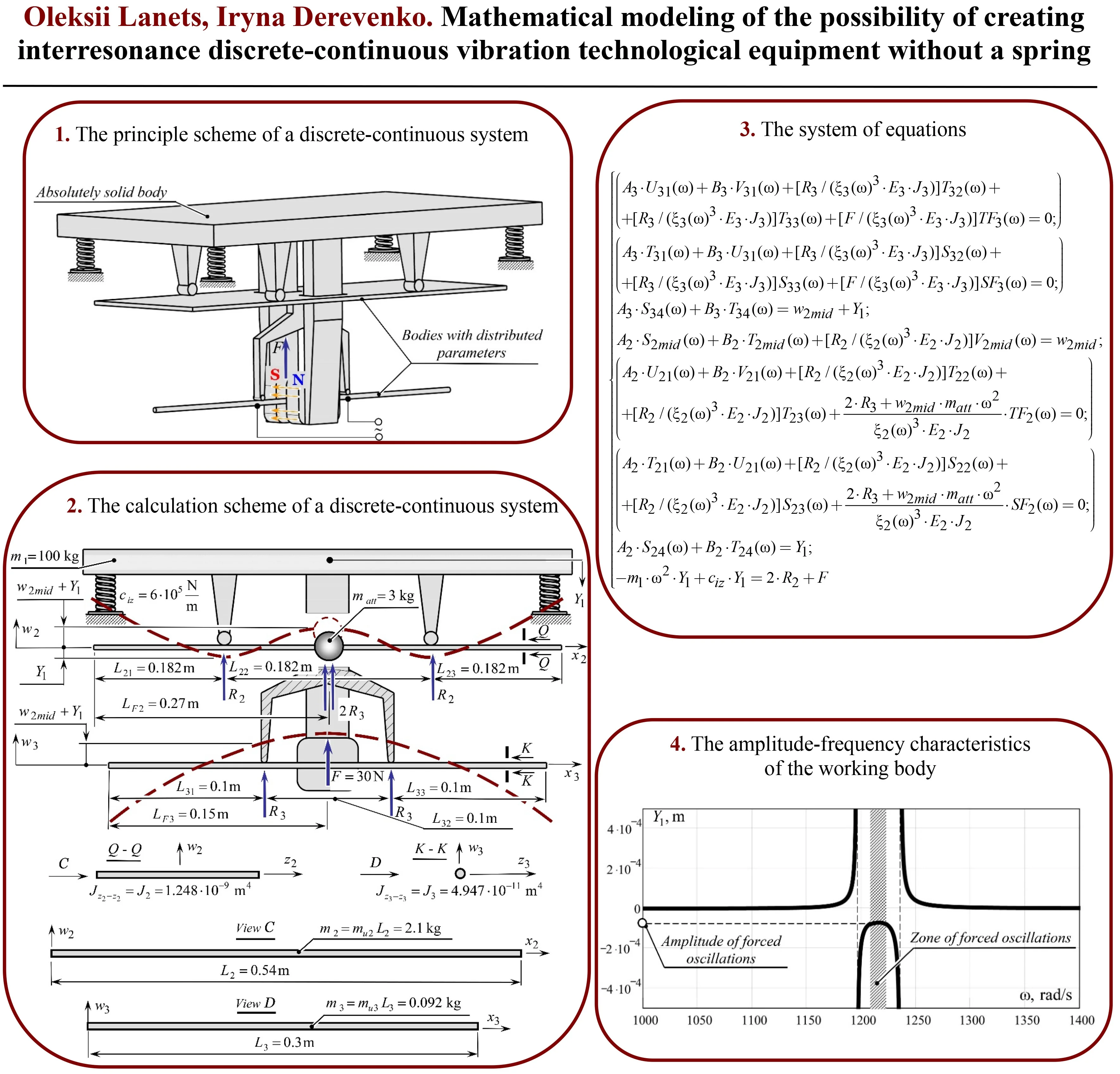
The concept of creating a discrete-continuous interresonance system without springs involves the use of two continuous sections connected in series to the working body of the vibrating machine (Fig. 1). The working body is considered to be a completely rigid body, and the two continuous sections are bodies with distributed parameters. The entire structure is installed on the foundation through twisted elastic elements (vibration isolators), the stiffness of which is .
Disturbance of the structure is carried out by applying an alternating supply voltage to the reactive continuous section (in Fig. 1, this is the lower body with distributed parameters, made of a steel bar). An alternating current flowing somewhere in the steel bar interacts with the magnetic field caused by the action of permanent magnets. Thanks to this, there is a disturbance force of alternating sign in the vertical direction (Ampere force), which sets the reactive continuous section in motion. Inertial forces caused by the movement of the reactive continuous section are transmitted to the intermediate continuous section (in Fig. 1, this is the upper body with distributed parameters), which resonates with the working body. Basically, we get an interresonant discrete-continuous oscillatory system without classical elastic elements. The function of elastic elements is performed by bodies with distributed parameters that have elastic properties. As we can see, this system is truly discrete-continuous, because the working body is considered as a non-deformable body.
Fig. 1The principle scheme of a discrete-continuous system
3. Calculation scheme and formation of a mathematical model of a discrete-continuous system
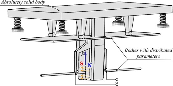
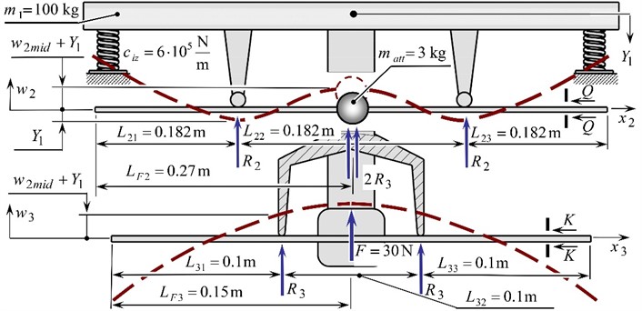
Two continuous sections (bodies with distributed parameters) are reduced to homogeneous beams, which are considered as bodies with distributed parameters with free ends (Fig. 2). The inertia of the reactive (in the lower figure) continuous section together with its fastening during the mathematical description of the intermediate continuous section is represented by the attached mass . To describe this oscillatory system, namely to find forced amplitudes of oscillations of a rigid body (working body) and bodies with distributed parameters, it was decided to use Krylov functions, which describe continuous sections reduced to beams. The combination of a continuous system with a discrete one will occur through the reactions in the hinge supports.
Fig. 2Calculation scheme of a discrete-continuous system with set values of some inertial, geometric and force parameters
The beams, to which the continuous sections are connected, are fixed in the corresponding hinged supports. We divide the beams into spans, the lengths of which are . The dynamic action from the vibrations of the beams is reflected in the reactions and in the resistances of the corresponding continuous sections. We consider that the beams perform transverse oscillations only in the planes , that coincide with the plane of action of the sign-changing total forced perturbation force .
Immediately, without detailed explanations, we predict that the form of oscillations of the reactive continuum section at the frequency of forced oscillations should be the first, and that of the intermediate continuum section – the second. That is, their design parameters should be such that they are perturbed according to the corresponding forms of oscillations – forms that turned out to be optimal for such a discrete-continuous system.
Based on the Krylov-Duncan functions, a system of equations was formed, which allows constructing the amplitude-frequency characteristic of the working body (mass ):
where:
Krylov-Duncan functions. , , , – constants; – deflection in the central part of the upper continuous section; , , , , , .
In addition, the following functions are additionally introduced: and , where is the circular frequency of the forced oscillations of the beam; and – modulus of elasticity of the corresponding continuous sections (2.1×10¹¹ Pa); and – moments of inertia of the cross-section of the beams relative to the neutral line perpendicular to the bending plane of the corresponding continuous sections; and – the masses of the unit lengths of the beams of the corresponding continuous sections.
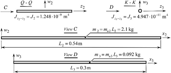
The system of Eq. (1) sets the amplitude of oscillations of the working body (parameter ) depending on the circular frequency of forced oscillations , that is, it allows to build a dependence . The first 7 equations describe a continuous system (two interconnected continuous sections). The last equation is responsible for the movement of the working body as a solid body. At first glance, this equation is quite simple, but it reflects the multifrequency of the system, because the continuous system enters it through reactions . Depending on the frequency of forced oscillations, we will observe different amplitudes of oscillations of the working body. So, the system of Eqs. (1) consists of 8 equations, because there are 8 unknowns, namely: , , , , , , and . We solve the system of Eq. (1) in the MathCAD 13 software using the Find function. Having previously set the initial values of the unknowns equal to 0, the amplitude-frequency characteristic of the working body of the discrete-continuous oscillating system was constructed with a variable circular frequency of forced oscillations (Fig. 3).
Fig. 3Amplitude-frequency characteristics of the working body of the discrete-continuous oscillating system
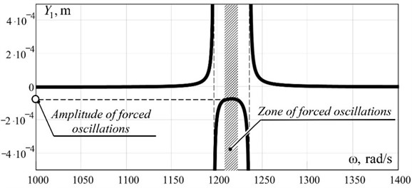
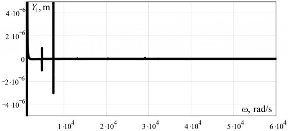
As can be seen from Fig. 3, at the amplitude value of the perturbation force 30 N at the frequency of 1220 rad/s (≈ 194 Hz) the working body mass 100 kg develops the amplitude of oscillations 0.00006 m, which is the equivalent of an overload of 9 terrestrial accelerations on the working body. The multifrequency nature of such a discrete-continuous system is confirmed by the amplitude-frequency characteristic built on the range (1×10³... 6×10⁴ rad/s) (Fig. 4).
Fig. 4Amplitude-frequency characteristics of the working body of the discrete-continuous oscillating system built on a wide range of circular frequency of forced oscillations
So, one of the advantages of the oscillating system proposed by the authors is that such an interresonance discrete-continuous oscillating system is implemented without classical elastic elements. The function of elastic elements is performed by bodies with distributed parameters that have elastic properties. Such a design has fewer parts and is a priori cheaper to manufacture compared to interresonance discrete oscillating systems.
However, it should be noted that the discrete-continuous oscillating system considered in the article can work optimally only at high frequencies. This is due to the fact that, theoretically, a reactive continuous section at low frequencies can have very high deflections, and this cannot be implemented in practice. In addition, the two continuous sections should be made of elastic steels that perform well under alternating cyclic loads. The disadvantages of such an interresonance oscillating system include the fact that it requires careful tuning, which complicates its use in industry.
4. Conclusions
The results of mathematical modeling indirectly confirm the possibility of realizing an inter-resonance mechanical oscillating system of vibrating technological equipment without springs. Such an oscillating system involves the use of two continuous sections connected in series to the working body of the vibrating machine.
References
-
P. Czubak, “Vibratory conveyor of the controlled transport velocity with the possibility of the reversal operations,” Journal of Vibroengineering, Vol. 18, No. 6, pp. 3539–3547, Sep. 2016, https://doi.org/10.21595/jve.2016.17257
-
R. Modrzewski, A. Obraniak, A. Rylski, and K. Siczek, “A study on the dynamic behavior of a sieve in an industrial sifter,” Applied Sciences, Vol. 12, No. 17, p. 8590, Aug. 2022, https://doi.org/10.3390/app12178590
-
S. Ogonowski and P. Krauze, “Trajectory control for vibrating screen with magnetorheological dampers,” Sensors, Vol. 22, No. 11, p. 4225, Jun. 2022, https://doi.org/10.3390/s22114225
-
V. Gursky, P. Krot, V. Korendiy, and R. Zimroz, “Dynamic analysis of an enhanced multi-frequency inertial exciter for industrial vibrating machines,” Machines, Vol. 10, No. 2, p. 130, Feb. 2022, https://doi.org/10.3390/machines10020130
-
N. Yaroshevich, O. Yaroshevych, and V. Lyshuk, “Drive dynamics of vibratory machines with inertia excitation,” in Mechanisms and Machine Science, Cham: Springer International Publishing, 2021, pp. 37–47, https://doi.org/10.1007/978-3-030-60694-7_2
-
V. Gursky, I. Kuzio, P. Krot, and R. Zimroz, “Energy-saving inertial drive for dual-frequency excitation of vibrating machines,” Energies, Vol. 14, No. 1, p. 71, Dec. 2020, https://doi.org/10.3390/en14010071
-
G. Filimonikhin and V. Yatsun, “Conditions of replacing a single-frequency vibro-exciter with a dual-frequency one in the form of passive auto-balancer,” Naukovyi Visnyk Natsionalnoho Hirnychoho Universytetu, Vol. 7, pp. 61–68, 2017.
-
G. Cieplok and K. Wójcik, “Conditions for self-synchronization of inertial vibrators of vibratory conveyors in general motion,” Journal of Theoretical and Applied Mechanics, Vol. 58, No. 2, pp. 513–524, Apr. 2020, https://doi.org/10.15632/jtam-pl/119023
-
Z. V. Despotovic, A. M. Pavlovic, and D. Ivanic, “Exciting force frequency control of unbalanced vibratory actuators,” in 20th International Symposium on Power Electronics (Ee), Oct. 2019, https://doi.org/10.1109/pee.2019.8923574
-
O. Lanets, “Fundamentals of analysis and design of vibratory machines,” (in Ukrainian), Lviv Polytechnic Publishing House, Lviv, Ukraine, 2018.
-
M. Pavlo, L. Oleksii, and S. Vadym, “Approximate calculation of the natural oscillation frequency of the vibrating table in inter-resonance operation mode,” Strojnícky časopis – Journal of Mechanical Engineering, Vol. 71, No. 2, pp. 151–166, Nov. 2021, https://doi.org/10.2478/scjme-2021-0026
-
O. Kachur et al., “Mathematical modeling of forced oscillations of continuous members of resonance vibratory system,” Vibroengineering Procedia, Vol. 38, pp. 13–18, 2021.
About this article

The authors have not disclosed any funding.
The datasets generated during and/or analyzed during the current study are available from the corresponding author on reasonable request.
The authors declare that they have no conflict of interest.
