Abstract
A comprehensive study on the influence of an inerter on the response of single-degree-of-freedom systems is presented; therefore, complete and thorough results for free and forced vibrations of linear SDOF systems with inerter are obtained. The free response results are for damped and undamped systems; moreover, the forced response solutions are for harmonic and arbitrary excitations. The classical problems of rotating unbalanced mass and support vibration isolation are solved.
Highlights
- Complete and thorough results for free and forced vibrations of linear single-degree-of-freedom systems with inerter
- The classical problems of rotating unbalanced mass and support vibration isolation are presented, with inerter
- New definitions for natural and damped frequencies, damping factor, amplification factor, transmissibility and transfer function
- Comprehensive study on the influence of an inerter on the response of SDOF systems
1. Introduction
The inerter device was introduced 15 years ago, when it originated from the control and electrical engineering community [1]; a literature review indicates that there are no comprehensive results, either from mechanical (vibrations) engineering or the civil engineering (earthquake engineering) community, for the free and forced response of a one-degree-of-freedom system with the device, which is the fundamental and primary system in Vibrations. Nevertheless, that review of late engineering literature shows great practical interest on the inerter (especially in the last five years); in particular, on its direct applications in the three engineering fields [2-4], as it is explained next.
From the vibroengineering or mechanical engineering perspective, the inerter is another or a new ideal component in discrete systems, as the dashpot or spring; it comes from electric circuit theory [1], particularly, from the study of analogies between electrical and mechanical systems [5]. A definition of inerter from Mechanical Vibrations will be: massless two-end component in which the force is proportional to the difference between the accelerations of the ends.
The inerter was first applied in mechanical engineering or automobile engineering [2, 6] as component of suspension systems, and it can be found in studies on dynamics of railway vehicles [7]. The device has been applied also in civil or earthquake engineering, where it has been mainly used as a new alternative to the traditional tuned mass dampers (TMD) [3, 8]. In control and electrical engineering, the inerter concept has also been lately applied [4, 9].
Regarding more fundamental work in mechanical or vibration engineering, Chen et al. studied the influence of inerters on discrete systems natural frequencies [10], and more recently Yang analyzed the influence of adding an inerter to the simple spring-damper linear isolation system [11]. Finally, and considering that the original concept or model of the device is linear, it is noted that very lately work has been published on its nonlinear behavior [12, 13].
As indicated in the first paragraph, or as a current literature review indicates, there is no thorough and complete analysis, either in mechanical or civil engineering sources, of the response of the vibrations fundamental system with the inerter; therefore, a full analysis of the free and forced response of an inerter-added one-degree-of-freedom system is a necessity and is presented herein, whose main outcome are many original and novel results for Mechanical Vibrations. The free response solutions are for both, damped and undamped systems, and the forced response results are for harmonic and nonperiodic or arbitrary excitations. In addition, the classical problems of rotating unbalanced mass and support harmonic vibration isolation are solved considering, of course, that an inerter is an additional component of both systems.
2. Characterization of the inerter as a vibrating system component
A definition of the inerter device from mechanical vibrations will be: massless two-end (or 2-terminal) component in which the force (at each end) is proportional to the difference between the absolute accelerations of the terminals. Inerters have been physically realized and a very simple version consists of a box or cylinder (right end) to which a flywheel and at least one gear are internally hinged through bearings, and the gear’s pinion rests on a rack which is finally the left terminal, as shown in Fig. 1; more schematically, let us have the inerter as in Fig. 2, with the dynamic variables that interest us: the displacements of the ends and the inerter force. Therefore, in the linear range, the fundamental equation that characterizes this component is:
where the proportionality constant is known as inertance, being the units of this b kilograms (kg).
Fig. 1A basic inerter device

Fig. 2Massless inerter depiction

It must be pointed out that the inerter, as the damper, does not have a favorite configuration: if one elongates an inerter, it will keep that displacement on the laboratory table (the spring of course tries to return to the undeformed configuration). Again, as the other discrete components (springs and dashpots) the inerter is assumed massless [1], and regarding the linearity expressed by Eq. (1), some work has very lately been done on nonlinearities involved in such geared devices [12-14].
Now, it is common in applications that springs and dashpots occur in certain combinations, and the same will happen for the new inerters; consequently, the concept of equivalent inerter will arise to simplify or simulate the action of a particular combination. As in the case of the classic components [15], a good start is to consider inerters connected in parallel and in series, as shown in Figs. 3(a) and 3(b), respectively. For the in-parallel case, a free body diagram of the massless (left or right) connecting structure implies that:
where F1 and F2 are the forces in the corresponding inerters. If the inerters are assumed to be linear, we have that:
From Eq. (2) it follows that:
where beq is the inertance of the equivalent inerter representing the combined effect of b1 plus b2; mathematically:
Fig. 3a) Inerters connected in parallel, b) inerters connected in series
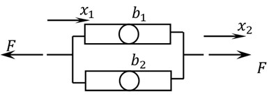
a)

b)
If several inerters (n) with inertances bi (i= 1, 2,…, n) are arranged in parallel, it is straightforward to show that:
Now, for inerters in series (Fig. 3(b)), these relations can be written:
Eliminating x0 from Eq. (7), we get again:
but in this case the equivalent inertance is:
If there are n inerters connected in series, it can be concluded that:
3. Differential equation of motion for linear systems with the inerter
As explained in the Introduction, a system of considerable recent interest in vibrations and structural dynamics is the spring-damper-inerter-mass system of Fig. 4; its differential equation of motion for its displacement (from the unstreched-spring position) x can be derived by Newton’s second law along with the free-body diagram of the main mass, which results in:
where F is the external force; this differential equation is better or more commonly written as:
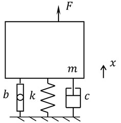
The equation of motion is the same for an inclined or vertical system, such as the one shown in Fig. 5. The only difference is that in this vertical case x does not measure displacement from the unstreched spring position but from the static equilibrium position; in this regard, it is interesting to note that an inerter, as the dashpot, does not have any favorite position or an unstreched position to return to: if an inerter is placed on a laboratory table and elongated, it will remain elongated.
Fig. 4SDOF system with damper and inerter
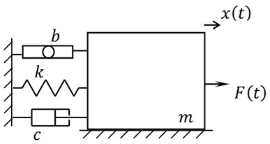
Fig. 5Vertical oscillatory system with inerter
4. Force-free response
Let us assume that for the system of Fig. 4 the external excitation is zero; in that case from Eq. (12), we get a homogeneous equation, or:
which is the general differential equation for free response. Now, in some cases damping is extremely low and can be ignored; in this instance the equation is simpler:
and its solution is obtained next.
4.1. Free response of an undamped system with inerter
We are concerned with the free and conservative case and its differential Eq. (14), which if divided by m, is reduced to:
where μ is the inertance-to-mass ratio [16], or:
and ωn is the natural frequency of the system without inerter. Thus, we are concerned with a linear second-order differential equation for which established solutions are exponential or of the form ert. Now, introducing this proposed solution into Eq. (15), we obtain the characteristic equation:
whose roots imply the exponential-form solution:
and the definition of a new concept, the natural frequency of the system with inerter or:
The solution can be put in a real and natural form by means of Euler’s formula and changing constants:
which is a harmonic response. The integration constants A' and ϕ' certainly depend on the initial conditions x(0)=x0 and ˙x(0)=v0, and can be shown to be:
We point out that there is an interesting result if the initial conditions are as a simple elongation or v0= 0: the amplitude of oscillation A' is equal to x0, and thus, equal to the amplitude of vibration that the system will have without the inerter; in fact, any other combination of initial conditions will result in different amplitudes of oscillation for both systems: the only conditions implying the same amplitude for the systems with and without the inerter is a null initial velocity. Other new and interesting results regarding response of MDOF systems to initial displacements and velocities have recently been obtained [17].
4.2. Free damped response
In case damping cannot be ignored, the equation of motion of the SDOF system with inerter and in free vibration is Eq. (13), or:
As it is expected, the solution of this differential equation is more involved than that of Eq. (15); nevertheless, standard and general mathematical procedures to solve ordinary and homogeneous differential equations can also be applied, that will result in the system response:
which is the free response of SDOF systems with inerter plus dashpot. In the very special case in which the inertance-to-mass ratio is set as μ=ξ2-1, that exponentially decaying response is simple to obtain by the order reduction method:
Now, for cases in which μ>ξ2-1, or ξ2-μ<1, the response is not simply exponential but oscillatory, thus of actual interest in Vibrations or in this work. The solution procedure starts with the acceptance of the appearance of two original concepts, one is a new dimensionless parameter that depends on the damping factor and the inertance-to-mass ratio, or:
and a new damped frequency:
Both of which are we emphasize novel results and allow us to write the solution as:
which can be written in a more natural form using a similar approach as in 4.1; thus, this vibratory response is finally:
The integration constants are now:
but if Eq. (29b) is used or calculated first, a much simpler expression for A is:
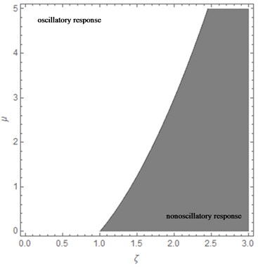
Now, as the type of response of these inerter systems depend on the value of ξ2-μ, or the values of ξ and μ, Fig. 6 is presented by which it can be defined whether the response is oscillatory (with exponentially decaying amplitude) or simply exponentially decaying, depending on the point (ξ, μ).
Fig. 6Diagram indicating oscillatory motion or not depending on ξ and μ
5. Forced response
If there is an external excitation in the form of force (not initial displacements or velocities), the equation of motion for the SDOF system is Eq. (12). The method to obtain the response of a system to a forcing function depends on the type or excitation or its dependence on time. In this section we first treat, harmonic excitation and its applications, and then present the response to a general or nonperiodic force.
5.1. Response to harmonic excitation
In this case, Eq. (12) can be written as:
We will be concerned with the case of the system not being simultaneously excited by initial conditions, which is the engineering or not mathematical case; in any case, the solution procedure is stablished in mathematics literature so that we do not demonstrate the final result step by step as in the previous Sections, even though the final result is original as well, which is this steady-state response:
Note that a new amplification (magnification) factor [15] appears:
In addition, there is also a new expression for the phase angle:
It is noted that Yang [11] has recently worked also on the magnification factor and has obtained an expression similar to that of Eq. (33); the difference is in the analysis which was nondimensional therein.
5.2. Rotating unbalance
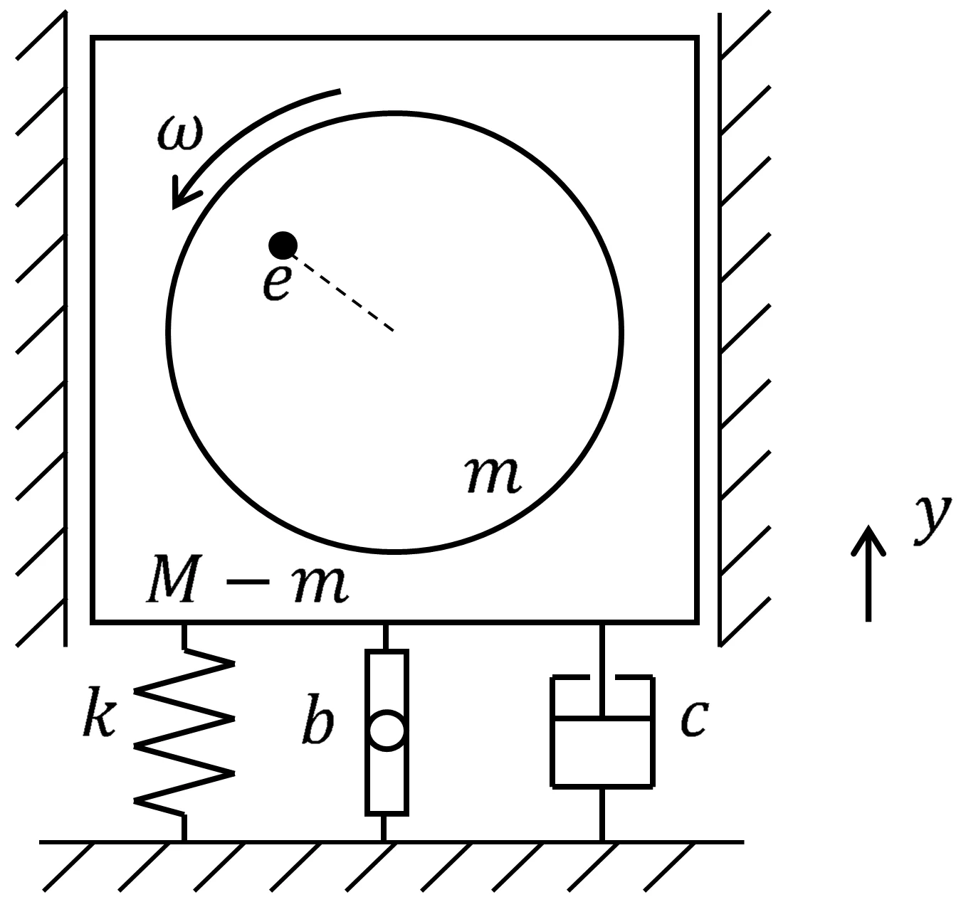
Actual or unbalanced rotating equipment in which the shaft is short (e.g. fans, clothes washers and dryers) can be modelled by a system such as the one shown in Fig. 7, where the new component or addition (with respect to what is found in Vibrations literature) is the inerter. The mass of the rotor or impeller is m and its center of mass is separated by a segment e from the shaft axis or rotor centroid, whereas M is the mass of the whole machine (rotor, shaft plus casing). The response of this system, rotating with a constant angular velocity ω, has not been presented previously in the literature; nevertheless, as in the last subsection (5.1), the response is not fully demonstrated because the procedure does not differ a lot from what it can be found in a good Vibrations book; therefore, only the original or final result is presented for design or direct engineering applications, which is:
It is the steady-state vibration y(t) of the machine, that is classically isolated (k-c) and additionally mounted on an inerter or a combination of these new devices (Section 2). Note that a new design (3-variable) function or amplitude response g arises:
Fig. 7Unbalanced rotating mass system with inerter
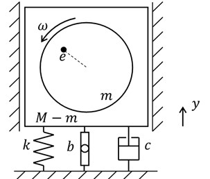
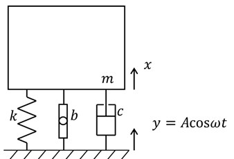
Fig. 8Support motion isolation system with inerter
5.3. Isolation from support or ground excitation
To separate a machine, device or structure from a moving support or ground is an important engineering action or subject in mechanical and civil engineering [18]. The system analyzed is the one shown in Fig. 8 where y(t) is the ground displacement and x(t) is the absolute displacement of an expensive and delicate device, or of a whole civil building, as hospitals and fire stations. Notice that if a building is isolated, it indeed behaves or responds as a rigid body or as a SDOF system; in other words, its elastic structural deformations will be almost vanished, that is the idea of seismic base isolation [18].
The first or basic case to be considered is that of harmonic motion of the support or ground; in other words, y=Acosωt; in this case, it can be demonstrated that the response of the inerter-added system will be:
It is stressed that also a new transmissibility function Tb appears, which is now a function of 3 variables:
5.4. Response to general excitations
The question now is what the response of a SDOF system with inerter (Fig. 4) is when the excitation is nonperiodic or arbitrary (Eq. (12)). This answer or solution can be achieved by the convolution integral or by the Laplace transform approach, among other methods (e.g. Fourier integral). If initial conditions are null, any method will result in the same answer or response [15].
In case the Laplace transform method is chosen, the new or inerter-added transfer function is:
and the response of the SDOF system will finally be:
where the frequencies ω'n and ω'd , and the new damping factor ξ' have been defined in Sections 4.1 and 4.2.
6. Conclusions
In this work, complete results for free and forced oscillatory response of a single-degree-of-freedom system with an inerter are presented. The free response solutions are for both, conservative (undamped) and damped systems, and the forced response results are for harmonic and for arbitrary or nonperiodic excitations. Comprehensive and thorough results as presented herein have not been published before in the vibrations or engineering literature.
Moreover, the classical applications of rotating unbalance and base motion vibration isolation are presented, including the new solutions associated to the addition of the inerter device to both engineering problems. These full and general results will serve to practitioners in civil, control, mechanical and electrical engineering; as demonstrated in the Introduction, the engineering applications of the new device are growing and are very diverse.
References
-
Smith M. C. Synthesis of mechanical networks: the inerter. IEEE Transaction on Automatic Control, Vol. 47, 2002, p. 1648-1662.
-
Smith M. C., Wang F. Performance benefits in passive vehicle suspensions employing inerters. Vehicle System Dynamics, Vol. 42, 2004, p. 235-257.
-
Lazar I. F., Neild S. A., Wagg D. J. Using an inerter-based device for structural vibration suppression. Earthquake Engineering and Structural Dynamics, Vol. 43, 2014, p. 1129-1147.
-
Chen M. Z. Q., Wang K., Shu Z., Li C. Realizations of a special class of admittances with strictly lower complexity than canonical forms. IEEE Transactions on Circuits and Systems I: Regular Papers, Vol. 60, 2013, p. 2465-2473.
-
Shearer J. L., Murphy A. T., Richardson H. H. Introduction to System Dynamics. Addison-Wesley, Reading, 1967.
-
Smith M. C., Swift S. J. Design of passive vehicle suspensions for maximal least damping ratio. Vehicle System Dynamics, Vol. 54, 2016, p. 568-584.
-
Wang F., Hsieh M., Chen H. Stability and performance analysis of a full-train system with inerters. Vehicle System Dynamics, Vol. 50, 2012, p. 545-571.
-
Ruiz R., Taflanidis A., Giaralis A., López D. Risk-informed optimization of the tuned mass-damper-inerter (TMDI) for the seismic protection of multi-storey building structures. Engineering Structures, Vol. 177, 2018, p. 836-850.
-
Pope S. A. Double negative elastic metamaterial design through electrical-mechanical circuit analogies. IEEE Transactions on Ultrasonics, Ferroelectrics and Frequency Control, Vol. 60, 2013, p. 1467-1474.
-
Chen M. Z. Q., Hu Y., Huang L., Chen G. Influence of inerter on natural frequencies of vibration systems. Journal of Sound and Vibration, Vol. 333, 2014, p. 1874-1887.
-
Yang J. Force transmissibility and vibration power flow behavior of inerter-based vibration isolators. Journal of Physics: Conference Series, Vol. 744, 2016, p. 012234.
-
Brzeski P., Perlikowski P. Effects of play and inerter nonlinearities on the performance of tuned mass damper. Nonlinear Dynamics, Vol. 88, 2017, p. 1027-1041.
-
González A., Lazar I. F., Jiang J. Z., Neild S. A., Inman D. J. Assessing the effects of nonlinearities on the performance of a tuned inerter damper. Structural Control and Health Monitoring, Vol. 24, 2017, p. e1879.
-
Papageorgiou C., Houghton N. E., Smith M. C. Experimental testing and analysis of inerter devices. Journal of Dynamic Systems, Measurement, and Control, Vol. 131, 2008, p. 011001.
-
Meirovitch L. Elements of Vibration Analysis. McGraw-Hill, Mexico, 1986.
-
Hu Y., Chen M. Z. Q., Shu Z., Huang L. Analysis and optimization for inerter-based isolators via fixed-point theory and algebraic solution. Journal of Sound and Vibration, Vol. 346, 2015, p. 17-36.
-
Morales C. A. On the conditions for synchronous harmonic free vibrations. Journal of Vibroengineering, Vol. 17, 2015, p. 3727-34.
-
Morales C. A. Transmissibility concept to control base motion in isolated structures. Engineering Structures, Vol. 25, 2003, p. 1325-1331.

