Abstract
The paper presents the results of experimental analysis features of rotation of two unbalance vibration exciters that excite oscillations of a chain-type two-mass oscillatory system in order to identify stability of synchronous modes of the debalances rotation near the system resonances (in application to analysis of resonant vibrating machines dynamics). Experimentally obtained amplitude-frequency characteristics of the model, velocities and mutual phase shift of rotation of the debalances are analyzed. Areas of stable synchronous rotation of the debalances and types of their self-synchronization are revealed as dependence of both the frequency of voltage supplying to the electric motors and the imbalances value. It is shown that when approaching the resonant frequencies, both the debalances rotational speeds and their mutual phasing appear to be unstable.
1. Introduction
The effect of self-synchronization of unbalance vibro-exciters is widely used in vibration excitation systems for various technological vibrating machines with several exciters [1-8]. In the same system, types of synchronization of the debalances can be different depending on the design parameters of the machine, oscillations excitation frequency and technological load, with the frequency of their synchronous rotation and the phase relationship being different [1, 2, 6]. Note that, the type of the debalances synchronization determines the vibrational excitation and, consequently, the shape of the system oscillations. At the same time, the oscillations shape determines the debalances synchronization type. Thus, the problem of how to provide the required type of vibration exciters synchronization at given oscillation modes (amplitude, frequency, and shape of oscillations) appears to be one of the main problems while creating highly efficient and reliable vibrating machines.
The literature devoted to theoretical analysis of self-synchronization of unbalance vibro-exciters in various mechanical systems is quite extensive [2, 9-17]. The general theory of unbalance vibro-exciters self-synchronization and the methods to solve basic problems of self-synchronization have been developed in [1-3, 5, 6, 9, 10, 13]. The problems of self-synchronization of two exciters in single and multiple degree-of-freedom systems are considered in [2, 7, 8, 11, 13, 15-17], and the conditions for existence of synchronous rotation modes for single-mass and two-mass oscillatory systems are obtained. The works [7, 8, 15, 16] are devoted to analysis of the conditions for the self-synchronization of exciters and the choice of design parameters and operating modes of oscillation excitation for some practical designs of vibrating machines. Some experimental results on the study of self-synchronization in single-mass and two-mass dynamic schemes of vibrating machines are presented in [2, 18], confirming the main theoretical results obtained in [2]. It is shown that the type of synchronization changes when the system passes through the resonance frequencies.
At the same time, for resonant machines with automatically controlled oscillation modes, it is of considerable interest to analyze synchronous motion regimes in resonant regions. In these regions, the system with an asynchronous electric drive most shows the features of nonlinear behavior to the utmost, which is caused by occurrence of relatively large oscillation amplitudes [2, 7, 8, 16, 18-20]. Some control systems for automatic adjustment and maintenance of resonant oscillations, which operating principle is based on measuring the phase relations between the exciting force and the oscillations, are considered in [19, 20]. Herewith, as shown in [20], neglecting the features of self-synchronization of exciters in control algorithms does not allow predicting the frequency of jump to the above-resonant region. Thus, one should either reduce the adjustment accuracy or increase the number of necessary measurements and their processing, which significantly complicates the measuring system and reduces its performance. The speed and efficiency of control algorithms can be significantly increased by taking into account the features of vibration exciters synchronization.
This work is devoted to experimental dynamics analysis of a two-mass chain-type oscillatory system with two almost identical unbalance vibration exciters driven by asynchronous electro motors. The dynamical scheme under consideration corresponds to a number of machines which are practically used for crashing, screening, transportation, and some other technological operations [2-4, 7, 8, 15]. Such studies are necessary since the existing literature provides no data concerning the instability of self-synchronization of unbalance exciters in a wide range of excitation frequencies, and especially near the resonances. To reveal the main features of the dynamics of such systems, the authors analyze the rotational speeds and the angles of the mutual phasing of the debalances at different excitation frequencies of the oscillations and at different values of the imbalance. Their rotational speed is controlled by changing the frequency of voltage supplied through the inverter to the winding of the induction motors with a squirrel-cage rotor.
2. Experimental model
The experimental model, Fig. 1, is a two-mass chain-type system consisting of two movable rigid bodies: the upper body 1 of mass m1 imitating the working body of a vibrating machine including an operational load, and the lower body 2 of mass m2. Two identical motor-vibrators 3 are rigidly attached to the lower body, symmetrically about the vertical axis Oy passing through its center of mass (m2 includes masses of the motor-vibrators).The bodies are connected to each other by a cylindrical helical spring 4, the body 2 is connected to the rigid frame 5 by means of the same two springs 6, and the body 1 is connected to the rigid frame 5 by means of two leaf springs 7. The rolling bushings 8 are attached to the edges of each body, and are able to move along the cylindrical rail guides 9, fixed parallel to each other on the frame 5. Thus, each body can move translationally only in the vertical direction along the axis Oy parallel to the longitudinal axes of the cylindrical guides 9. Fig. 2 shows a design scheme corresponding to the model.
Fig. 1Experimental model
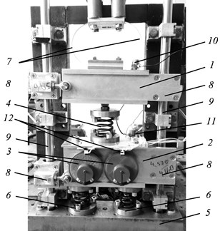
Fig. 2Design scheme
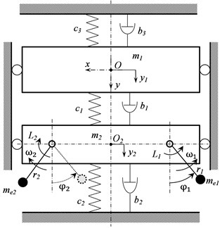
Each of the motor-vibrators of asynchronous type has squirrel-cage rotor with two pole pairs, i.e. the synchronous speed is twice less than the frequency of the supply voltage. There are identical disks with additional debalances installed eccentrically at both ends of the shaft of each motor-vibrator. The additional debalances are in the form of one, two or three bolts, which ensures three different imbalance values: 57, 223 and 453 gr∙mm for each of the disks. Both motor-vibrators are powered by a single inverter, which allows for the debalances rotational speed to be controlled by changing frequency of the supply voltage. Moreover, the motor-vibrators are connected to the power supply so that when the supply voltage is applied, the motors’ shafts rotate in opposite directions, towards each other.
The model has the following values of main parameters: m1= 2.63 kg, m2= 4.57 kg, c1= 35.7 kN/m, c2= 71.4 kN/m, c3= 2.6 kN/m, nominal speed of the motor-vibrators is 1340 rpm at 50 Hz supply frequency; nominal torque is 649×10-4 Nm; maximum torque is 970×10-4 Nm.
Accelerometers 10 and 11 (Fig. 1), fixed at the bodies 1 and 2, are used for measuring oscillations. Averaged rotational speed of the debalances and their angular position are measured by optical encoders 12, which generate electrical impulses when the debalances are in their upper position.
3. Experimental methodic
Experimental methodic is to determine the amplitude-frequency responses of the system by vibration signals measured by accelerometers; to define the relations between the frequency of the supply voltage and the debalances rotational speed; and to determine the debalances relative angular position measured by the encoders depending on the power supply frequency. These characteristics were obtained with a discrete change in power supply frequency in the range from 20 Hz to 75 Hz, and, accordingly, change in the debalances rotational speed in the range from 10 Hz to 37.5 Hz. In order to identify possible non-linearities of the system, the experiments were carried out at both increasing and decreasing speed of the debalances, as well as at various values of motor-vibrators imbalance. The frequency step was 0.5 Hz. In the range of the first resonance frequency, it was decreased to 0.1 Hz. The duration of each frequency step ensured achievement the steady oscillations of the system. Thus, the necessary accuracy of the investigated characteristics was achieved.
Oscillation forms of the system were determined by comparison of phases of the bodies oscillations. The mutual shift of the debalances rotation phases was measured by a time interval between the pulses from the optical encoders of each motor-vibrator. The tests were repeated for three different values of the imbalances.
For measurement and test control, a software-hardware complex, based on the NI-cRIO real-time controller and LabVIEW software, was developed. The complex allows increasing or decreasing, according to the predetermined law, the power supply frequency applied to the motors, registering the measured signals, as well as their further processing in order to determine the amplitudes and frequencies of oscillations, the debalances rotational speed, calculate the relative rotational angle between debalances, and build the frequency response.
4. Analysis of the model oscillations
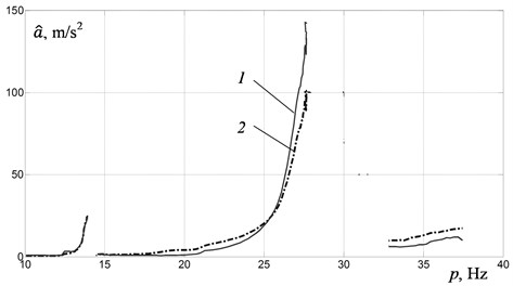
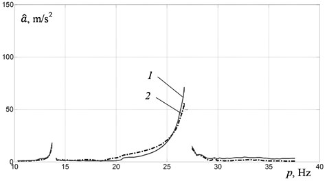
Fig. 3 shows the amplitude-frequency responses of the upper (curve 1) and the lower (curve 2) bodies, obtained with increasing (Fig. 3(a)) and decreasing (Fig. 3(b)) rotational frequency of the debalances at maximum imbalance. It is clear that there are two resonance frequencies at 14 Hz and 27.6 Hz in the investigated frequency range. And with increasing frequency, there are jumps in amplitude and frequency from 14 Hz to 14.4 Hz when passing through the first resonance, and from 27.6 Hz to 32.8 Hz when passing through the second resonance. In case of decreasing frequency, when passing through resonance frequencies, one can observe a sharp increase in the amplitude of the oscillations and a jump in their frequency from 27.4 Hz to 26.7 Hz when passing through the second resonance, and from 14 Hz to 13.7 Hz when passing through the first resonance. Jumps in the amplitudes and frequencies of oscillations indicate the manifestation of nonlinear properties of the system under consideration due to interaction with an asynchronous electric drive of the unbalance exciters.
Fig. 3Amplitude-frequency responses of: a) the bodies obtained with increasing, b) decreasing of power supply frequency: 1 – for the upper body, 2 – for the lower body
a)
b
Fig. 4 shows amplitude-frequency responses of the upper body obtained with increasing frequency at different values of imbalance. Increase in imbalance value leads to increase in oscillations amplitudes. However, the oscillation frequencies at which the jumps in amplitudes and frequencies occur when passing through the resonances remain the same independently of imbalance value. The jump grows up with increasing imbalance. No jumps were observed at minimum imbalance, i.e. the system does not show nonlinearity.
Fig. 4Amplitude-frequency responses of the upper body obtained at different imbalances: 1 – at maximum imbalance, 2 – at medium imbalance, 3 – at minimum imbalance
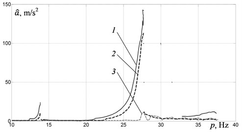
When comparing the recorded oscillograms of the bodies oscillations at resonant frequencies it was found that they oscillate in phase at the first resonance frequency, while at the second resonant frequency the oscillation form corresponds to their antiphase motion.
Fig. 5The debalances rotational frequency depending on the power supply frequency: 1 – with increasing of power supply frequency, 2 – with decreasing of power supply frequency
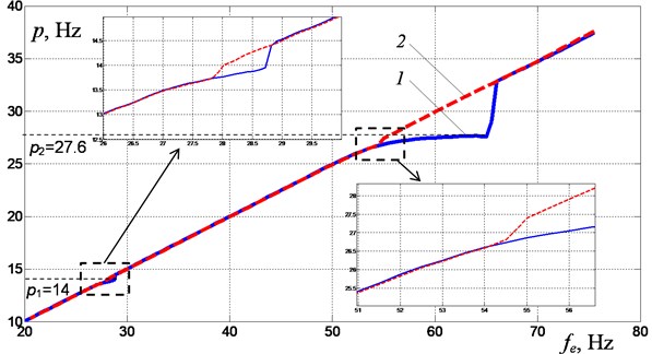
Simultaneously with determination of the amplitude-frequency responses and the oscillations forms of the model, the rotational speed of the debalances was measured. Fig. 5 demonstrates graphs of the debalances rotational speed depending on the frequency of the supply voltage: increasing frequency (curve 1), decreasing frequency (curve 2), at maximum imbalance. Resonant areas, indicated by dashed rectangles, are represented on the same graph on an enlarged scale. It can be seen from curve 1 that near the resonance frequencies of the system oscillations, the rate of change in the rotational speed slows down. And this deceleration is more noticeable near the second resonance frequency. In other words, near the second resonance the motors speed get jammed, when the motor speed practically remains unchanged with increasing power supply frequency. These deceleration effects are caused by additional “vibrational” torque acting on the motors’ shafts due to the system’s oscillations, and by slip in asynchronous motors of limited power.
In case of decreasing power supply frequency, the effects of speed jamming appear less distinct.
Fig. 6 shows the debalances speed depending on power supply frequency at different imbalances.
Fig. 6The debalances rotational frequency depending on the power supply frequency: 1 – at maximum imbalance, 2 – at medium imbalance, 3 – at minimum imbalance
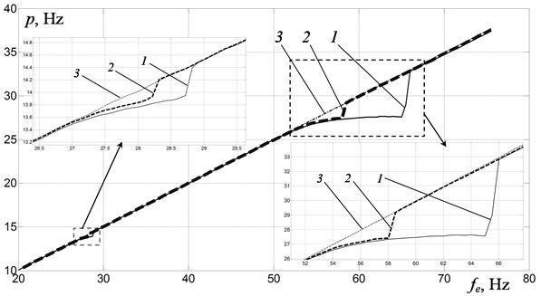
It is seen that in the regions of both resonances, an increase in the imbalance leads to a substantial expansion of the jamming zones and, correspondingly, jumps in the motors rotational frequency to above-resonant region. This is due to a corresponding increase in the oscillations amplitudes, which in turn lead to an increase in vibrational torque and in the energy dissipation in the system. As a result, it becomes harder to overcome resonance with the same motors. With minimal imbalance, the effect of the debalances speed jamming is not appeared. The presented here characteristic effects of the debalances speed jamming, as well as the abrupt changes in the frequency and amplitude of the system’s oscillations, are manifestations of the so-called Sommerfeld effect typical for nonlinear systems with a drive of limited power [1, 21, 22].
4.1. Analysis of the debalances mutual phasing
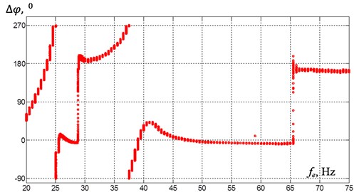
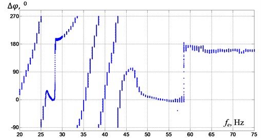
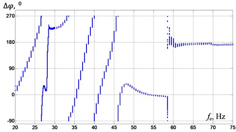
Fig. 7 shows the measurement results of mutual phase shift between the left-hand-side debalance and the right-hand-side debalance depending on power supply frequency with its slow increase for different imbalances. Each point on the graph corresponds to the magnitude of the mutual phase shift Δφ measured successively through one complete turn of the left-hand-side debalance. Thus, the height of “column” of points characterizes the change in mutual phase at a given power supply frequency, and accordingly, the degree of synchronism of their rotational speeds - the smaller the height of the “column”, the closer the debalances’ rotational speeds to each other. When Δφ= 0°, the debalances rotate in opposite directions synchronously in phase, while at Δφ= 180° the debalances rotate synchronously in antiphase.
In case of maximum imbalance (Fig. 7(a)) no synchronization of the debalances is noticed in the frequency range of 20-25 Hz (before the first resonance), which is due to small oscillations amplitudes of the lower body carrying the exciters. The amplitudes increase as coming closer to the first resonance. This helps setting the type of self-synchronization with mutual phase shift Δφ near 0° and strictly vertical excitation. Moreover, the closer to the resonant frequency, the smaller is the height of the “columns”, i.e. the higher the degree of synchronization. When passing the first resonance, immediately after the jump in frequency and amplitudes, one can notice an abrupt change in type of self-synchronization of the debalances (Δφ ≈ 180°). For such debalances mutual phasing the vertical excitation disappears, while a torque and horizontal force appear, which are taken up by rail guides. With a further increase in power supply frequency up to a frequency (approximately 42 Hz) corresponding to the antiresonance frequency of the system, the mutual phasing changes chaotically. After this frequency, an increase in oscillations amplitudes of the system is observed, and the phase shift stabilizes near Δφ= 0°. At the same time, the height of the “columns” decreases up to a certain value of the power supply frequency, but just before the jump takes place, the “columns” grow, which indicates that the debalances rotate more unevenly. When passing the second resonance, immediately after the jump, the mutual phase shift changes by 180°, and stabilizes near this value with a further increase in the power supply frequency. The vertical excitation disappears again.
In case of medium imbalance (Fig. 7(b)), when coming closer both to the first and to the second resonance, stable synchronization of debalances with the phase shift near 0° occurs at noticeably higher power supply frequency than in case of maximum imbalance. This behaviour is associated with the value of the excited oscillation amplitudes, which significantly affect the synchronization conditions. When approaching the second resonance, the height of the “columns” first decreases, but it noticeably increases immediately before the jump. After the second resonance, the phase shift stabilizes near 180°.
In case of minimal imbalance (Fig. 7(c)), stable synchronization with the phase shift of about 0° is observed only in a relatively narrow frequency band near the second resonance, which is also due to the amplitudes of the oscillations excited. No stable synchronization of the debalances is observed up to 52 Hz of power supply frequency. When passing through the second resonance, the phase shift abruptly changes by about 180°, and then stabilizes near this value.
Fig. 7The debalances mutual phase shift depending on the power supply frequency: 1 – at maximum imbalance, 2 – at medium imbalance, 3 – at minimum imbalance
a)
b)
c)
5. Conclusions
The experimental researches have shown that, despite the linearity of the system resilient member characteristics, the oscillating system demonstrates features of a nonlinear system. Such behavior results from the fact that moment characteristics of the asynchronous motors of the unbalance exciters are non-ideal. The change in frequency of debalances synchronous rotation leads to different mutual phase shift of debalances. Stable types of debalances synchronization with mutual phase shift near 0° occur when approaching the resonance frequencies of the system. Stability of phase shift increases as the system approaches the resonant frequency. However, just prior to the oscillations jump, unevenness of the debalances rotational speed and instability of the mutual phase shift are appeared. Passing through the resonance is followed by abrupt change in mutual phase shift by approximately 180°. An increase in the exciters imbalance, all other conditions remain unchanged, due to the increase in the system oscillations amplitudes, leads to expansion of the oscillations frequencies range within which the debalances synchronization types remain stable. Moreover, this leads to an increase in power supply frequencies corresponding to the oscillations jumps to above-resonance regions.
The revealed features of vibration exciters self-synchronization near resonance in such systems are usually not taken into account, due to the fact that when solving problems of self-synchronization, as a rule, they are limited to the study of analytical solutions in the first approximation. The resulting stable solutions imply that, at a given frequency of supply voltage, the debalances will rotate evenly with a constant mutual phase shift. However, this is inconsistent with the observed in practice instability of rotational speeds and phase shifts near resonances. Such circumstance is essential for tuning vibratory machines with unbalance exciters to the resonant oscillation mode.
References
-
Blekhman I. I. Vibrational Mechanics. Nonlinear Dynamic Effects, General Approach, Applications. World Scientific, Singapore, 2000.
-
Blekhman I. I. Synchronization of Dynamical Systems. Nauka, Moscow, 1971.
-
Blekhman I. I. Theory of Vibration Processes and Devices. Vibration Mechanics and Vibration Technology. ID Ruda I Metally, St. Peterburg, 2013.
-
Lavendelis E. E. Vibration in the Technique. Handbook, Vol. 4, Vibration Processes and Machines. Mechanical Engineering, Moscow, 1981.
-
Dresig H., Holzweibig F. Dynamics of Machinery. Theory and Applications. Springer, Heidalberg, 2010.
-
Nijmeijer H., Rodriguez-Angeles A. Synchronization of Mechanical Systems. World Scientific, Singapore, 2003.
-
Vaisberg L. A., Zarogatsky L. P., Turkin V. Ya. Vibrating Crushers. Basics of Calculation, Design and Technological Application. Izdatelstvo VSEGEI, St. Peterburg, 2004.
-
Vaisberg L. A. Design and Calculation of Vibrating Screens. Nedra, Moscow, 1986.
-
Bleckman I. I., Fradkov A. L., Tomchina O. P., Bogdanov D. E. Self-synchronization and controlled synchronization: general definition and example design. Mathematics and Computers in Simulation, Vol. 58, Issues 4-6, 2002, p. 367-384.
-
Nagaev R. F. Dynamics of Synchronizing Systems. Springer-Verlag Berlin Heidelberg, 2003.
-
Balthazar J. M., Felix J. L. P., Brasil R. M. L. R. F. Short comments on self-synchronization of two non-ideal sources supported by a flexible portal frame structure. Journal of Vibration and Control, Vol. 10, Issue 12, 2004, p. 1739-1748.
-
Balthazar J. M., Felix J. L. P., Brasil R. M. L. R. F. Some comments on the numerical simulation of self-synchronization of four non-ideal exciters. Applied Mathematics and Computation, Vol. 164, Issue 2, 2005, p. 615-625.
-
Paz M., Cole D. Self-synchronization of two unbalanced rotors. Journal of Vibration and Acoustic, Vol. 114, Issue 1, 1992, p. 37-41.
-
Dimentberg M. F., Gobb E., Mensehing J. Self-synchronization of transient rotations in multiple shaft systems. Journal of Vibration and Control, Vol. 7, Issue 2, 2001, p. 221-232.
-
Nagaev R. F., Shishkin E. V. Self-synchronization of inertial vibration exciters of vibratory cone crusher. ObogashchenieRud, Vol. 1, 2003, p. 33-36.
-
Shishkin E. V., Kazakov S. V. Self-synchronization of vibration exciters of cone crusher with three-mass system. ObogashchenieRud, Vol. 5, 2016, p. 32-37.
-
Antipov V. I., Palashova I. V. Dynamics of a two-mass parametrically excited vibration machine. Journal of Machinery Manufacture and Reliability, Vol. 39, Issue 3, 2010, p. 238-243.
-
Panovko G. Y., Shokhin A. E., Eremeikin S. A. Experimental analysis of the oscillations of a mechanical system with self-synchronized inertial vibration exciters. Journal of Machinery Manufacture and Reliability, Vol. 44, Issue 6, 2015, p. 492-496.
-
Panovko G., Shokhin A., Eremeykin S. On a problem of resonance mode tuning for vibration machines. Herald of the Bauman Moscow State Technical University, Vol. 4, 2017, p. 106-111.
-
Eremeikin S. A., Krestnikovskii K. V., Panovko G. Ya., Shokhin A. E. Experimental analysis of the operability of a system to control the oscillations of a mechanical system with self-synchronizing vibration exciters. Journal of Machinery Manufacture and Reliability, Vol. 45, Issue 6, 2016, p. 553-558.
-
Niselovskaya E. V., Panovko G. Ya., Shokhin A. E. Oscillations of the mechanical system, excited by unbalanced rotor of induction motor. Journal of Machinery Manufacture and Reliability, Vol. 42, Issue 6, 2013, p. 457-462.
-
Kononenko V. O. Oscillatory Systems with Limited Excitation. Nauka, Moscow, 1964.
About this article
The research was supported by Russian Science Foundation (Project No. 18-19-00708).

