Abstract
Aiming at the low-frequency line spectrum noise characteristics of power equipment noise, based on the principle of energy degradation, this paper combines the energy degradation sound insulation structure with the dynamic vibration absorption technology for the first time and applies it to the research field of noise control of power equipment in substations. Dynamic vibration absorption technology is used to effectively control low-frequency vibration and noise. Considering that there is an upper limit to the capacity of DVA, the sound-vibration energy degradation design of the transformer is completed by setting a sound insulation structure on the outside of the original transformer housing. It is analyzed that the vibration energy of the sound insulation structure in the specific frequency band is significantly reduced compared to the transformer housing, realizing efficient degradation of the vibration energy of the transformer housing and effective isolation of sound radiation. Through the optimized design of dynamic vibration absorption for the sound insulation structure, the structural sound isolation ability at the target frequency is further strengthened, and the system noise radiation level is greatly reduced under the action of multiple mechanisms at the target frequency, verifying the feasibility and high efficiency of the optimal DVAs energy degradation design of the transformer.
Highlights
- The combination of energy degradation sound insulation structure and dynamic vibration absorption technology is applied to the research field of noise control of substation power equipment.
- The sound insulation structure is set on the outer side of the original transformer housing to complete the design of the transformer sound and vibration energy degradation.
- Through the dynamic vibration absorption optimization design of the sound insulation structure, the sound isolation ability of the target frequency structure is further strengthened.
1. Introduction
With the rapid development of social economy, the electricity demand in residential and commercial fields has shown a significant rising trend. It is urgent to implement effective control of substation noise. In power transmission and transformation projects, the noise generated by power equipment has significant low-frequency line spectrum noise characteristics. As one of the commonly used means in the field of vibration control, dynamic vibration absorption can effectively control low-frequency vibration noise. It is highly compatible with the noise control requirements of power equipment mainly characterized by line spectrum noise radiation at frequencies such as 100 Hz and 200 Hz, and has extremely broad application prospects.
The dynamic vibration absorber (DVA) mainly works based on the principle of the tuned mass damper. By attaching a mass-spring system to the main vibration system, the natural frequency of the mass-spring system is matched with a specific frequency of the main system. When the main system is vibrated by external excitation, the mass of the DVA will generate relative motion under the action of the spring, thereby absorbing the vibration energy of the main system and reducing the vibration amplitude of the main system.
Sound insulation technology is a commonly used noise reduction method in substations [2, 3]. Generally, people set up sound insulation enclosures and sound barriers around transformers to cut off the noise transmission path. Some scholars [4-7] have proposed hanging sound insulation baffles outside the transformer oil tank and assembling semi-enclosed sound insulation enclosures to block noise transmission. Regarding the research on dynamic vibration absorption, Jolly et al. [8] proposed to place the DVAs on the surface of an elastic plate which effectively reduced the sound power value near the absorption frequency. Considering the situation that the action frequency of the DVAs and power equipment coupling shifts, our team [9] comes up with an idea of optimizing the shifted frequency by adjusting the parameters of the DVAs, which contributes to minimizing the global acoustic index and improving the noise reduction effect of the DVAs.
Take the influence of the insulating oil fluid load inside the transformer into consideration, we can know that vibration energy of the transformer housing is huge. The mass of the oscillator of the DVA is limited, so the absorption efficiency of housing vibration energy is limited. To achieve efficient control of low-frequency noise of power equipment and to reach the optimal effect, our team uses near-body sound insulation technology to achieve effective isolation of transformer sound radiation as well as considerable reduction of vibration energy of sound radiation structures. By applying DVA treatment to the sound insulation structure after energy degradation, the noise reduction efficiency of dynamic vibration absorption is further enhanced. The existing research is to simply set up a sound insulation barrier and install the DVA directly in combination with the noise reduction equipment. In this paper, the energy-degraded sound insulation structure is combined with the dynamic vibration absorption technology for the first time and applied to the research field of noise control of substation power equipment. Dynamic vibration absorption technology is used to effectively control low-frequency vibration and noise.
2. Basic principle of energy degradation
During operation, transformers generate various forms of energy. Their noise mainly comes from the vibration energy generated by the transformer body and cooling device, and the noise generated by vibration is emitted in the form of sound waves to the surrounding area through the air. Applying the principle of energy degradation to the vibration and noise reduction of transformers, a sound insulation structure is designed around them. The sound insulation structure can act as a solid physical barrier to block the noise generated by transformers from spreading to the surrounding environment.
The oil in the transformer is a heavy fluid with high density and viscosity. When the transformer is working, the oil may cause the vibration of the wall due to the action of the electromagnetic field. However, due to the heavy nature of the oil, directly pasting the DVAs on the wall may not be able to effectively absorb the complex vibration caused by the oil. As a light fluid, air has low density and viscosity, and its vibration transmission is relatively simple. In the air around the transformer, the vibration is mainly transmitted in the form of low-frequency sound waves. In contrast, the vibration characteristics of air are more likely to be predicted and analyzed. Therefore, installing an energy-degraded structure in the air and attaching DVAs to it can be more targeted to deal with air-borne vibration. Choosing to install an energy-degraded structure in the air can avoid a direct impact on the structure of the transformer wall.
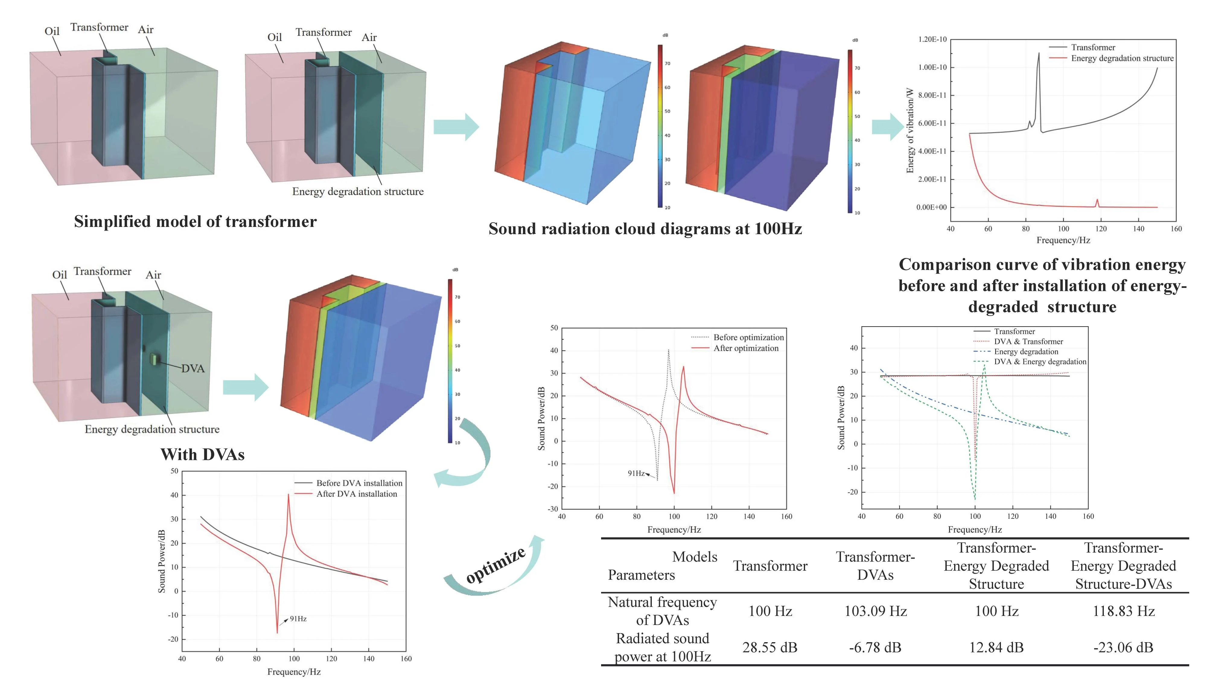
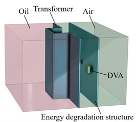
To verify the noise reduction effect of the energy-degraded sound insulation structure, the “oil-transformer-air” sound radiation model is established to simulate the sound transmission mechanism of the transformer “internal insulating oil-housing-external air”, as shown in Fig. 1(a). The insulating oil side of the model is defined as unit sound pressure input, and a simplified transformer sound radiation model after the installation of the degraded housing is established. By comparing the changes in sound radiation on the air side before and after the installation of the energy-degraded sound insulation structure, the noise reduction performance of the energy-degraded sound insulation structure is verified.
In order to verify the noise reduction effect of the energy degradation sound insulation structure, the “oil-transformer-air” acoustic radiation model is established to simulate the acoustic transmission model of the transformer internal insulating oil-transformer housing-external air. As shown in Fig. 1(a), the pink area is the transformer oil, the concave and convex housing is the simplified transformer housing, the green area is the air area, and the insulating oil side of the acoustic transmission model is defined as the unit sound pressure input. Furthermore, the noise reduction performance is verified by establishing a simplified energy-degraded sound insulation structure on the outside of the transformer housing. The simplified energy-degraded structure is a green plate, and the air domain is between the outside and inside of the plate and the transformer housing, as shown in Fig. 1(b). By comparing the acoustic radiation changes on the external air side before and after the installation of the energy-degraded sound insulation structure, the sound insulation and noise reduction performance of the energy-degraded sound insulation structure is verified and analyzed. The parameters of the established transformer sound radiation model are shown in Table 1.
Fig. 1Simplified model of transformer
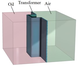
a) Before installation of energy-degraded sound insulation structure
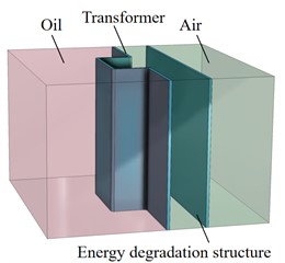
b) After installation of energy-degraded sound insulation structure
Table 1Model materials and parameters
Parameters | Materials | ||
Transformer oil | Steel | Air | |
Density (kg/m3) | 993 | 7850 | 1.2 |
Sound velocity (m/s) | 1450 | – | 343 |
housing thickness (mm) | – | 6 | – |
Young’s modulus (Pa) | – | 2.16×10¹¹ | – |
Poisson’s ratio | – | 0.28 | – |
Loss factor | – | 0.001 | – |
By calculating the two different transformer simplified models shown in Fig. 1, the 100 Hz sound field cloud diagram of the transformer acoustic radiation model before and after the installation of the energy-degraded sound insulation structure can be obtained, as shown in Fig. 2.
Fig. 2Sound radiation cloud diagrams at 100 Hz before and after installation of energy-degraded sound insulation structure
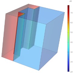
a) Before installation of energy-degraded sound insulation structure
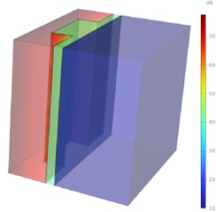
b) After installation of energy-degraded sound insulation structure
The cloud diagram of the model after the installation of the energy-degraded sound insulation structure is shown in Fig. 2(b). The air domain between the inner side of the energy-degraded sound insulation structure and the transformer housing is green, and the outer air domain of the degradation structure is dark blue, which indicates that the noise reduction performance of the energy-degraded sound insulation structure is significant. After the installation of the degradation structure, the noise radiation of the transformer model is significantly reduced. By sorting out the data, the 100 Hz radiated sound power of the model before and after the installation of the energy-degraded sound insulation structure is 28.55 dB and 12.84 dB respectively. Thus, proves that the noise reduction effect is remarkable after the installation of the energy-degraded sound insulation structure.
The vibration energy of transformer housing is huge, whose main source is the vibration of the iron core and winding transmitted to the transformer housing. After designing the energy-degraded sound insulation structure using near-body sound insulation technology, the vibration energy, after attenuation in the air, will be greatly reduced when it reaches the energy-degraded sound insulation structure. The vibration energy curves of the transformer housing and the energy-degraded sound insulation structure are shown in Fig. 3. The vibration energy at the energy-degraded sound insulation structure is significantly lower than that at the transformer housing, and the air domain between the two plays a certain buffering role. When the transformer housing vibrates, the vibration energy transmitted through the air will be weakened in the air domain. The low stiffness and damping characteristics of the air make the energy of the vibration wave gradually attenuate when it propagates, thus reducing the vibration energy transmitted to the energy-degraded sound insulation structure, and achieving energy degradation relative to the transformer housing.
3. DVAs of energy-degraded sound insulation structure
The energy-degraded structure can be designed and adjusted as needed to adapt to different vibration frequencies and amplitudes. At the same time, the type, quantity and installation position of the vibration absorber can be more flexibly selected by attaching the DVAs to the energy-degraded structure to achieve the best vibration absorption effect. DVAs are suitable for vibration and noise reduction of power equipment that mainly radiates line spectrum noise. Installing them on the surface of the energy-degraded sound insulation structure can effectively reduce the vibration amplitude on its surface. Since noise radiation is closely related to vibration, reducing this vibration further reduces the noise radiation level. Finally, efficient and accurate control of noise radiation of power equipment is achieved.
Fig. 3Comparison curve of vibration energy before and after installation of energy-degraded sound insulation structure
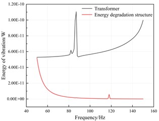
Fig. 4Simplified model of transformer with additional DVAs
To verify the noise reduction effect of the DVA, a simplified transformer sound radiation model with three DVAs attached to the surface of the energy-degraded sound insulation structure is established as shown in Fig. 4. The natural frequency of the DVAs is 100 Hz. It has a mass of 1 kg and a stiffness of 3.9478×10⁵ N/m. Additionally, the Young's modulus is 2.16×10¹¹ Pa, Poisson’s ratio is 0.28, and the loss factor is 0.01. By doing the calculation, the sound field cloud diagram of the transformer 100 Hz sound radiation model after the DVAs is attached to the surface of the energy-degraded sound insulation structure can be obtained as shown in Fig. 5.
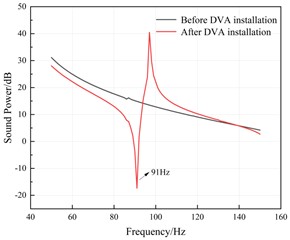
As can be seen from Fig. 5, after installing the DVAs on the energy-degraded sound insulation structure, the color on the air side of the model cloud diagram is lighter than that before installation. This indicates that installing the DVAs appears to weaken the noise reduction effect of the transformer model. After sorting out the data, the 100 Hz radiated sound power of the model before installing the DVAs is 12.84 dB, and after installation it is 22.04 dB. It can be seen that after installing the DVAs with the same target frequency, the radiated sound power of the transformer increases instead of decreasing. In order to study the reason for this phenomenon, the comparison curve of the radiated sound power of the system before and after installing the DVAs is shown in Fig. 6.
As can be seen from Fig. 6, prior to the installation of the DVAs, the radiated sound power curve of the model within the analyzed frequency band is a smooth curve without obvious fluctuations. After installing the DVAs, a significant valley emerges in the sound radiation curve at 91 Hz, and the noise radiation of the model at this frequency is notably reduced. In other frequency ranges, due to the coupling effect between the DVAs and the energy-degraded sound insulation structure after installation, the modal changes occur, and the sound power curve fluctuates at certain frequencies. At 100 Hz, the sound radiation of the model after installing the DVAs is higher than that before installation. This phenomenon is completely different from the expected noise reduction effect of the DVAs, and the operating frequency has shifted within a certain range. Hence, it is necessary to optimize and adjust the natural frequency of the DVAs in order to achieve the optimal control of the radiated noise at the 100 Hz frequency of power equipment.
Fig. 5Sound radiation cloud diagram at 100 Hz after installation of DVAs
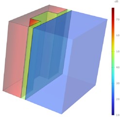
Fig. 6Comparison curve of radiated sound power of the system before and after installation of DVA
4. Low-frequency noise reduction optimization design
When the natural frequency of the DVAs is 100 Hz, its operating frequency has shifted, and the offset reaches 9 Hz. This indicates that there is a certain difference between the frequency at which the DVAs actually functions and the initially set natural frequency [10-12]. After comprehensive consideration and analysis, in order to more efficiently reduce the calculation amount during frequency optimization, it is decided to set the initial value of the optimization calculation to 108 Hz. This setting is based on a full understanding of the frequency offset situation and optimization considerations for calculation efficiency. By choosing 108 Hz as the initial value, it can be closer to the frequency range actually needing optimization to a certain extent, thereby reducing unnecessary calculation steps and time consumption in the optimization process and improving the efficiency and accuracy of frequency optimization. Regarding the control of 100 Hz noise radiation of power equipment, reference [9] optimizes the natural frequency of the DVAs. The basic parameters of the optimization model are presented in Table 2.
Table 2Parameters of the natural frequency optimization model of the DVAs at 100 Hz
Parameter name | Parameter definition |
Objective function | 100 Hz radiated sound power |
Optimization parameter | Natural frequency of DVAs |
Parameter range | 50 Hz-150 Hz |
Initial value | 108Hz |
Optimization tolerance | 0.01 |
According to the above parameters, the natural frequency optimization work of the DVAs can be carried out, and the optimal natural frequency of the DVAs can be obtained. The iterative convergence curve of the 100 Hz system radiated sound power and the natural frequency of the DVAs is shown in Fig. 7. As depicted in Fig. 7, with an initial frequency of 108 Hz, when the optimization model is utilized, following 33 iterations, the radiated sound power of the system converges and stabilizes at –23.06 dB. This value corresponds to a natural frequency of 118.83 Hz for the DVAs. The radiated sound power curve of the 100 Hz system after the natural frequency of the DVAs is optimized is presented in Fig. 8.
Fig. 7Convergence curve of 100 Hz system radiated sound power and natural frequency of DVAs
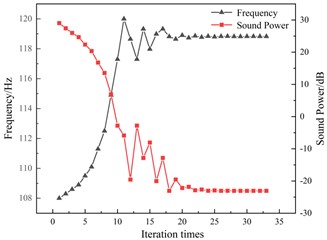
Fig. 8System radiated sound power diagram after natural frequency optimization of DVAs
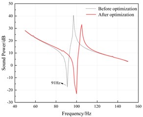
As can be seen from Fig. 8, after optimizing the natural frequency of the DVAs, the radiated sound power of the system at 100 Hz is significantly reduced to –23.06 dB. When compared with the value of 22.04 dB before optimization, the total sound power difference is 45.1 dB, which is notable. The optimized natural frequency of the DVAs matches the main noise frequency of the transformer, thereby generating resonance. At this moment, the mass block of the DVAs vibrates at the maximum amplitude. Through this resonance effect, the vibration energy of the energy-degraded sound insulation structure is effectively transferred to the DVAs. As a result, the vibration amplitude of the energy-degraded sound insulation structure is greatly reduced. For noise generation, the reduction in vibration amplitude directly leads to a decrease in noise radiation.
After optimizing the natural frequency of the DVAs, the combined design formed with the energy-degraded sound insulation structure exhibits a remarkable synergistic noise reduction effect. To verify the optimal design of the DVAs and the energy-degraded sound insulation structure, the radiated sound power of four sound radiation models, namely the transformer model, the transformer-DVAs model, the transformer-energy-degraded sound insulation structure model, and the transformer-energy-degraded sound insulation structure-DVAs model, is compared, as shown in Figure 9.
As can be seen from Fig. 9, after performing energy degradation design on the transformer, the radiated sound power of the system in the analyzed frequency band is significantly reduced. After installing the DVAs on the transformer, the radiated sound power of the system becomes smaller within the operating frequency range. After implementing the optimal DVAs and energy degradation design, the system noise radiation level is further reduced. The calculation results of different models are shown in Table 3.
As can be observed from Table 3, after implementing the optimal DVAs and energy degradation design on the transformer, the system sound radiation power at 100 Hz is the smallest. Compared with the transformer casing, the noise reduction amount reaches 51.61 dB, and the noise reduction effect is excellent. The energy-degraded sound insulation structure can absorb a portion of the noise energy, effectively block the propagation path of noise, reduce the transmission of sound waves, and significantly reduce the noise and vibration generated by the transformer and transmitted to the surrounding environment, achieving energy degradation relative to the transformer casing. Installing the DVAs directly on the transformer casing, considering the influence of the inner insulating oil load, the vibration energy of the transformer casing is enormous. Due to the limited mass of the oscillator of the DVAs, the absorption efficiency is limited, and the vibration and noise reduction effect is also limited. After attaching DVAs to the energy-degraded sound insulation structure, the noise reduction effect is the best. The two can work synergistically to jointly reduce noise from different angles, verifying the feasibility of the optimal DVAs and energy degradation design of the transformer.
Fig. 9Comparison of radiated sound power of different model systems
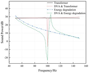
Table 3Comparison of calculation results of different models
Parameters | Models | |||
Transformer | Transformer-DVAs | Transformer-energy degraded structure | Transformer-energy degraded structure-DVAs | |
Natural frequency of DVAs | 100 Hz | 103.09 Hz | 100 Hz | 118.83 Hz |
Radiated sound power at 100Hz | 28.55 dB | –6.78 dB | 12.84 dB | –23.06 dB |
5. Conclusions
In this paper, with a focus on the difficulty of low-frequency noise control for power equipment, the dynamic vibration absorption technology of power equipment based on energy degradation is studied. Specifically, the energy-degraded sound insulation structure design and the optimal DVAs and energy degradation design are carried out respectively for transformers. By taking the simplified model of the transformer as the analysis object, the optimization design, analysis, and verification work are conducted. As a result, the following conclusions are obtained.
1) The design of an energy-degraded sound insulation structure is carried out for the transformer. The results indicate that after the installation of this structure, the system noise radiation and vibration energy within the analyzed frequency band are remarkably reduced. This validates that the energy-degraded sound insulation structure has outstanding sound insulation performance and achieves energy degradation in comparison to the transformer housing.
2) Upon further conducting the DVAs design based on the energy degradation design, the coupling effect between the two leads to a change in the modal. Consequently, the operating frequency of the DVAs shifts within a certain range. After frequency optimization, a remarkable noise reduction effect is achieved.
3) After implementing the optimal DVAs and energy degradation design on the transformer, the remarkable synergistic noise reduction effect of the two is evident. They jointly reduce noise from different perspectives, and the system noise radiation level is greatly reduced. This verifies the feasibility of the optimal DVAs and energy degradation design for the transformer.
References
-
X. Wang, B. Yang, J. You, and Z. Gao, “Coarse-fine adaptive tuned vibration absorber with high frequency resolution,” Journal of Sound and Vibration, Vol. 383, pp. 46–63, Nov. 2016, https://doi.org/10.1016/j.jsv.2016.07.030
-
Wang G. et al., “Study on sound insulation properties of polycarbonate / nano-silica composites,” High-voltage Electrical Apparatus, Vol. 55, No. 11, pp. 295–298, 2019, https://doi.org/10.13296/j.1001-1609.hva.2019.11.044
-
Zhang S. et al., “Sound insulation performance of metal / rubber damping layer composite structure,” High-voltage Electrical Apparatus, Vol. 55, No. 11, pp. 273–276, 2019, https://doi.org/10.13296/j.1001-1609.hva.2019.11.040
-
S. Foster and E. Reiplinger, “Charcteristics and control of transformer sound,” IEEE Transactions on Power Apparatus and Systems, Vol. 100, No. 3, pp. 1072–1077, Mar. 1981, https://doi.org/10.1109/tpas.1981.316573
-
R. S. Girgis, M. S. Bernesjo, S. Thomas, J. Anger, D. Chu, and H. R. Moore, “Development of ultra-low-noise transformer technology,” IEEE Transactions on Power Delivery, Vol. 26, No. 1, pp. 228–234, Jan. 2011, https://doi.org/10.1109/tpwrd.2010.2070812
-
W. Chen, “Design and analysis of low noise power transformer,” Zhejiang University of Technology, Hangzhou, 2014.
-
Mao W. et al., “Design and research on natural ventilation sound insulation cover of outdoor box-type distribution transformer,” Noise and Vibration Control, Vol. 30, No. 3, pp. 148–152, 2010, https://doi.org/10.3969/j.issn.1006-1355.2010.03.039
-
M. R. Jolly and J. Q. Sin, “Passive tuned vibration absorbers for sound radiation reduction from vibrating panels,” Journal of Sound and Vibration, Vol. 191, No. 4, pp. 577–583, Apr. 1996, https://doi.org/10.1006/jsvi.1996.0141
-
J. Ma, J. Wu, M. Geng, B. Ma, and C. Shen, “Optimal analysis on low frequency line spectrum sound control of power equipment using dynamic vibration absorber,” Vibroengineering Procedia, Vol. 41, pp. 117–123, Apr. 2022, https://doi.org/10.21595/vp.2022.22535
-
Q. Wang et al., “Dual-function quasi-zero-stiffness dynamic vibration absorber: low-frequency vibration mitigation and energy harvesting,” Applied Mathematical Modelling, Vol. 116, pp. 636–654, Apr. 2023, https://doi.org/10.1016/j.apm.2022.12.007
-
K. Liu and J. Liu, “The damped dynamic vibration absorbers: revisited and new result,” Journal of Sound and Vibration, Vol. 284, No. 3-5, pp. 1181–1189, Jun. 2005, https://doi.org/10.1016/j.jsv.2004.08.002
-
Y. Chang, J. Zhou, K. Wang, and D. Xu, “A quasi-zero-stiffness dynamic vibration absorber,” Journal of Sound and Vibration, Vol. 494, p. 115859, Mar. 2021, https://doi.org/10.1016/j.jsv.2020.115859
About this article

This work was financially supported by Science and Technology Project of State Grid Corporation of China (5500-202358515A-3-2-ZN).
The datasets generated during and/or analyzed during the current study are available from the corresponding author on reasonable request.
The authors declare that they have no conflict of interest.
