Abstract
In order to obtain the vibration response characteristics of the propeller spindle system effectively and accurately, and provide the basis for the subsequent fault diagnosis, the modal simulation and test of the spindle model were carried out. With the propeller set as eccentric mass, the amplitude and torsion angle of the spindle model were simulated under the condition of excited vibration and unexcited vibration respectively, and the frequency response of bending and torsion under the coupled condition was obtained. The newmark- method was used to solve the transient response of the bent-torsional coupling model. The results shows that when the propeller spindle system undergoes rotation at a specific frequency and experiences bending vibration excitation force, the latter will induce torsional vibration response. Moreover, the amplitude of the torsional vibration response varies with changes in the frequency of the bending vibration excitation force.
Highlights
- In order to obtain the vibration response characteristics of the propeller spindle system effectively and accurately, and provide the basis for the subsequent fault diagnosis, the modal simulation and test of the spindle model were carried out.
- With the propeller set as eccentric mass, the amplitude and torsion angle of the spindle model were simulated under the condition of excited vibration and unexcited vibration respectively, and the frequency response of bending and torsion under the coupled condition was obtained.
- The newmark-β method was used to solve the transient response of the bent-torsional coupling model.
1. Introduction
The vibration of the propulsion shaft has a significant impact on the entire ship's power system, and it is closely related to the safety of navigation [1]. Therefore, studying the vibration of the propeller shaft is crucial. Among different forms of shafting vibration, bending and torsional vibrations have the most profound impact on the normal operation of the entire system. Bending vibration has been studied extensively due to its obvious performance, while torsional vibration has received less attention until recently [2-3]. However, both types of vibrations significantly affect equipment operation and can lead to serious accidents. Understanding their mechanisms plays a guiding role in analyzing shaft failures and finding solutions for accidents. Additionally, understanding these mechanisms provides an important theoretical basis for preventing and diagnosing ship faults. With ships becoming larger and faster, studying only one type of vibration is no longer sufficient to solve shafting problems [4]. Therefore, research on coupled vibrations has become more important, with bending-torsional coupling being one of the key areas. In the context of propeller spindle coupling vibration, there exists a mutual influence between bending and torsional vibrations [5-6]. Bending vibration induces new torsional vibration, while torsional vibration in turn promotes new bending vibration. Furthermore, a distinct bent-torsional coupling resonance phenomenon is observed within this type of vibration, where the torsional vibration induced by flexural motion amplifies the amplitude of the flexural vibration. With advancements in marine technology, it has become evident that single-mode bending or torsional vibrations are insufficient to fully characterize shafting dynamics. Through an investigation into flexural and torsional coupling vibrations, we can more accurately simulate actual shafting operational conditions and comprehensively elucidate its vibrational mechanism. This research scheme can provide a theoretical basis and a fault diagnosis scheme for the abnormal vibration of the spindle system, and can also provide a method for the abnormal vibration according to the obtained coupling vibration law.
2. Modal analysis of spindle
2.1. The establishment of finite element model
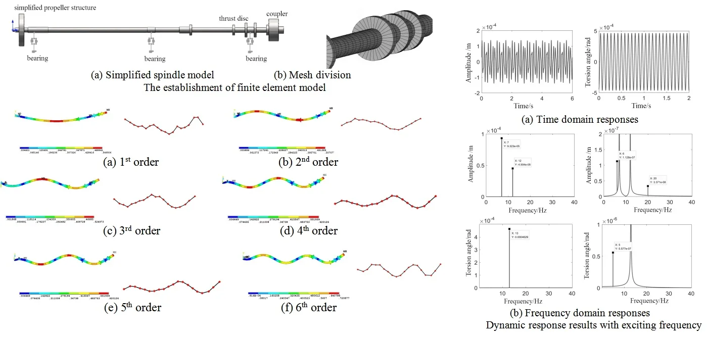
Modal analysis is extensively employed in the study of mechanical structures, drawing upon vibration theory to derive modal parameters inherent to the structure. These parameters encompass natural frequency, modal mode, and damping ratio within different modal orders. In accordance with the actual structural configuration of the propeller spindle, the model is suitably simplified. Specifically for the propeller component of the system, both the mass and moment of inertia are condensed and directly integrated at the geometric center of the propeller. Consequently, in contrast to its real-world counterpart, the model constructed within ANSYS analysis software omits a disk used for simulating mass and moment of inertia at the propeller. Instead, modeling employs APDL command flow to replicate shaft segments with varying diameters through distinct beam sections. To improve the accuracy and computational efficiency of finite element analysis, the propeller shaft model was simplified. Due to the large mass and moment of inertia of the propeller, the rigid disk model was used for simulation, which could ensure the reliability and realism of the analysis results. Since the propeller shaft system has no concentrated mass, the beam element can be used for simulation. In addition, the constraints on the position of the bearing can be controlled by the defined bearing unit.
In modal analysis, the consideration of shafting supporting factors and the back part of elastic coupling is deemed unnecessary. The propeller's additional mass is simplified to a concentrated mass added at its geometric center. The system model established based on the simplified results is depicted in Fig. 1(a). The beam 188 beam element is employed for mesh division to simulate the structure of the shaft. By specifying the size and length of the section, the shaft is divided into 32 equal parts, obviating the need for further mesh division, as shown in Fig. 1(b). When determining the length of each section, efforts are made to ensure uniformity in order to minimize calculation errors.
Fig. 1The establishment of finite element model
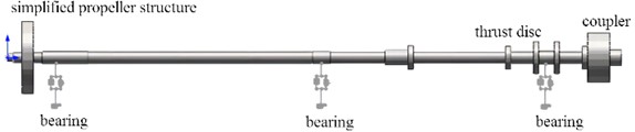
a) Simplified spindle model
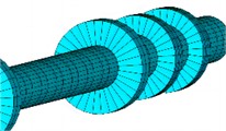
b) Mesh division
2.2. Modal simulation and test
The propeller spindle serves as a critical mechanism for facilitating hull movement by transferring power from the main engine to the propeller, thereby driving its rotation. Subsequent generation of axial thrust upon propeller rotation is transmitted through the system to the thrust bearing, which in turn conveys force to the hull, enabling forward or backward propulsion of the ship. The inherent characteristics of this system exert significant influence on the dynamic behavior of the hull. In the modal testing procedure, a force hammer is used to apply an excitation force to the shafting model. The acceleration sensor is positioned at the end point of the shafting and tapped sequentially at each measurement point for single-point excitation, as shown in Fig. 2. Subsequently, each tap and its corresponding signal are recorded individually, and the acquired signals are subjected to FFT transformation using analysis software for frequency response analysis. Ultimately, this process leads to identification of modal parameters, followed by output of identification parameters and mode animation.
Through finite element calculation and test, the natural frequency and mode shape of the spindle can be obtained as shown in Table 1 and Fig. 3, respectively. According to the analytical results, since the spindle system is a strictly axisymmetric structure, in the free state, the bending vibration will appear two modes with the same natural frequency as the mode shape. The effective natural frequency of the first order is 4.28 Hz, and the maximum vibration displacement is located at the installation position of the propeller. For the solution of modal analysis, there are multiple methods to choose. The Black Lanczos method uses only a single sparse solver in the analysis process, which has fast convergence speed and strong ability to solve large-scale problems with symmetric structures. Subspace method can control the iterative process in computation, and there are many functions to control this process, it can also solve large symmetric structure problems. Simplification has a fast convergence rate. First, the system matrix is reduced, and then the system frequency is solved.
Table 1Natural frequency under different order
Order | 1 | 2 | 3 | 4 | 5 | 6 |
Simulation results of natural frequency / Hz | 4.28 | 4.96 | 13.35 | 13.79 | 22.37 | 22.86 |
Test results of natural frequency / Hz | 4.57 | 5.26 | 13.04 | 14.88 | 22.75 | 23.24 |
Fig. 2Modal test scheme
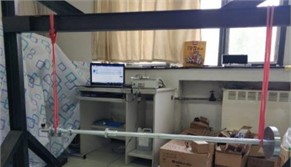
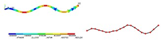
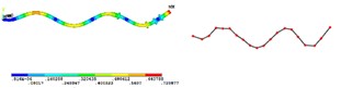
Fig. 3Simulation and test of mode shape under different order
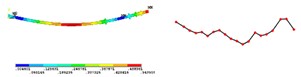
a) 1st order
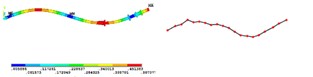
b) 2nd order
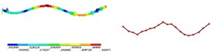
c) 3rd order
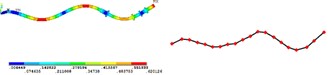
d) 4th order
e) 5th order
f) 6th order
3. Establishment of coupling model and calculation of dynamic characteristics
3.1. Transient analysis method
In order to further study the coupled bending and torsional vibration caused by mass eccentricity, based on the modal analysis, the transient dynamic analysis is introduced to solve the composite response results at a specific excitation frequency. In the transmission system, the propeller has the largest mass and moment of inertia compared with the other components of the shaft system, and the mass imbalance caused by the mass eccentricity of the other components is negligible compared with the propeller.
The Newmark- method is used to solve the transient response of the bent-torsional coupling model. In transient analysis, it is first necessary to define the total time and the time interval for the analysis to run. Considering the bearing support, the coupled dynamic equation can be denoted as in Eq. (1):
where is mass matrix, is gyroscopic matrix, is stiffness matrix, is damping matrix, is generalized load, is spindle operating frequency.
In the iterative operation, the effective stiffness matrix can be expressed as:
where and are working condition coefficient.
3.2. The influence of mass eccentricity on vibration
In the absence of external excitation force, the influence of the rotation frequency of the spindle on the bending-torsional coupling vibration is analyzed only under the action of mass eccentricity. When the rotating frequency of the propulsion shafting is 9 Hz (normal operating frequency), the bending vibration response at the propeller node, the torsional vibration response of the propeller can be obtained by numerical calculation, as shown in Fig. 3. It is evident that in the absence of external excitation force, the propulsion shaft-system model of the propeller exhibits a single peak at a rotation frequency of 9 Hz, with the abs ordinate frequency aligning at approximately 9 Hz, corresponding to the model's rotation frequency. This peak value can be attributed to the bending amplitude induced by the eccentricity of the propeller mass. In scenarios lacking external excitation force, there is no excitation force in torsional vibration direction, rendering it challenging to assess its potential impact on bending vibration. Consequently, applying torsional direction excitation torque becomes imperative for determining such influence. In the absence of an exciting force in the torsion direction, a minor peak at 18 Hz frequency is observed. This suggests that the torsional amplitude is induced by bending vibration, with the bending vibration frequency caused by propeller mass eccentricity matching both the rotational speed of the model and resulting in a value of 18 Hz for torsional vibration. Consequently, it can be inferred that under mass eccentricity, bending vibration influences the amplitude of torsional vibration; however, its impact remains minimal at this juncture.
Fig. 4Dynamic response results without exciting force
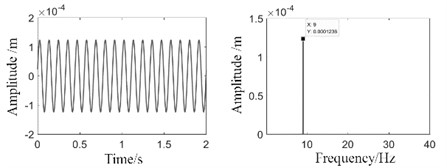
a) Time and frequency domain responses of amplitudes
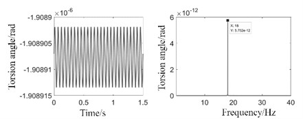
b) Time and frequency domain responses of torsion angle
3.3. Influence of external exciting frequency on vibration
Based on the outcomes of the modal shape analysis, external excitation is exerted on the propeller spindle model, and the bending and torsional vibration responses at the propeller nodes can be derived through numerical calculation, as presented in Fig. 5. It is observable that as the rotation frequency of the system amounts to 7 Hz and the frequency of the external excitation force stands at 2 Hz, the peak value at 7 Hz correlates to the bending vibration response triggered by the mass eccentricity, and the peak value at 12 Hz is associated with the bending vibration response induced by the excitation force frequency. When the upper bound of the vertical coordinate of the frequency domain plot for the bending vibration is reduced, two peaks with lower magnitudes emerge, with the abscissa frequencies being 6 Hz and 20 Hz. From the torsional analysis findings, it can be discerned that the external excitation torque at a frequency of 13 Hz surpasses the bending vibration, indicating that the torsional vibration can have an impact on the bending vibration. After the upper limit of the ordinate of the frequency domain diagram of torsional vibration is lowered, a peak frequency of 5 Hz will manifest in the spectrum diagram. Since the frequency of the external excitation force of the bending vibration is 12 Hz, it is verified that the bending vibration can influence the torsional vibration.
Fig. 5Dynamic response results with exciting frequency
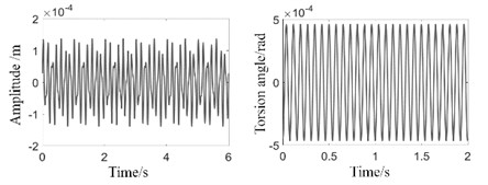
a) Time domain responses
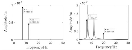
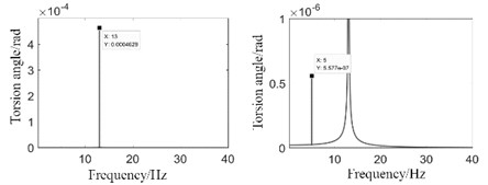
b) Frequency domain responses
3.4. Influence of rotation frequency on vibration
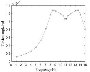
The bending excitation force of the system was maintained constant, and the rotational frequency was varied to explore the relationship between the torsion amplitude value induced by the bending vibration and the system rotational frequency. To investigate the influence of rotational frequency on the vibration of the rotating shaft, a torsion-free vibration excitation torque is applied in the model, and the vibration response at the propeller node can be acquired by numerical calculation, as presented in Fig. 6.
When the rotation frequency of the spindle system ascends from 1 Hz to 15 Hz, the distribution of torsion amplitude values is approximately symmetrical and axially symmetric in comparison to that at 11 Hz. When the rotation frequency of the system varies, the torsional amplitude changes in a symmetrical manner, and the symmetry axis is the external excitation force frequency of the bending vibration. When the rotation frequency approaches the sum or difference of the flexural excitation force frequency and the natural frequency of the torsional vibration, the torsional vibration induced by the flexural vibration attains a peak value.
Fig. 6Torsion angle response at different rotation frequencies
4. Conclusions
1) When there is no external exciting force, the propeller’s mass eccentricity will induce bending vibration response at a frequency equal to the rotation frequency. This bending vibration will subsequently lead to torsional vibration, albeit with minimal amplitude. When the spindle system experiences an external exciting force causing bending vibration, it will induce torsional vibration response at a frequency corresponding to the difference between the exciting force frequency and the rotational frequency. Furthermore, under the influence of torsional vibration external excitation moment, it will induce bending vibration response at a frequency equivalent to either the difference or sum of torsional excitation moment frequency and rotational frequency.
2) The mass eccentricity of the propeller induces bending vibration, and the amplitude of this response increases with the rotation frequency. Torsional vibration has minimal impact on flexural vibration in the absence of external excitation. As the rotation frequency changes, if the exciting force for bending vibration remains constant, the amplitude of torsional vibration induced by bending will vary with rotation frequency. When the rotation frequency approaches either the sum or difference between the exciting force frequency for bending vibration and natural torsional vibration frequency, maximum torsional amplitude is reached.
References
-
A. Daşdemir, “A modal analysis of forced vibration of a piezoelectric plate with initial stress by the finite-element simulation,” Mechanics of Composite Materials, Vol. 58, No. 1, pp. 69–80, Mar. 2022, https://doi.org/10.1007/s11029-022-10012-7
-
R. Swan, J. Penney, G. Corson, J. Nazario, and T. Schmitz, “Surface location error in robotic milling: Effect of combined low frequency and high frequency vibration modes,” CIRP Journal of Manufacturing Science and Technology, Vol. 49, No. 1, pp. 203–215, Apr. 2024, https://doi.org/10.1016/j.cirpj.2024.01.011
-
X. Zheng, S. Zhang, Y. Zhang, J. Li, and Y. Zhang, “Investigation on operational stability of main shaft of a prototype reversible pump turbine in generating mode based on ensemble empirical mode decomposition and permutation entropy,” Journal of Mechanical Science and Technology, Vol. 36, No. 12, pp. 6093–6105, Nov. 2022, https://doi.org/10.1007/s12206-022-1124-4
-
H. D. Chalak, A. M. Zenkour, and A. Garg, “Free vibration and modal stress analysis of FG-CNTRC beams under hygrothermal conditions using zigzag theory,” Mechanics Based Design of Structures and Machines, Vol. 51, No. 8, pp. 4709–4730, Aug. 2023, https://doi.org/10.1080/15397734.2021.1977659
-
Z. Wang, S. Chen, W. He, Z. Wang, and Z. Xia, “Research for the bearing fit effect on the vibration characteristics of spindle rotor-bearing system,” Journal of Mechanical Science and Technology, Vol. 37, No. 12, pp. 6257–6270, Dec. 2023, https://doi.org/10.1007/s12206-023-1104-3
-
S. de Carolis, A. Messina, and L. Soria, “Modal analysis through response-based FRFs: Additional modes for local diagnoses,” Journal of Sound and Vibration, Vol. 549, No. 1, p. 117574, Apr. 2023, https://doi.org/10.1016/j.jsv.2023.117574
About this article

The authors have not disclosed any funding.
The datasets generated during and/or analyzed during the current study are available from the corresponding author on reasonable request.
The authors declare that they have no conflict of interest.
