Abstract
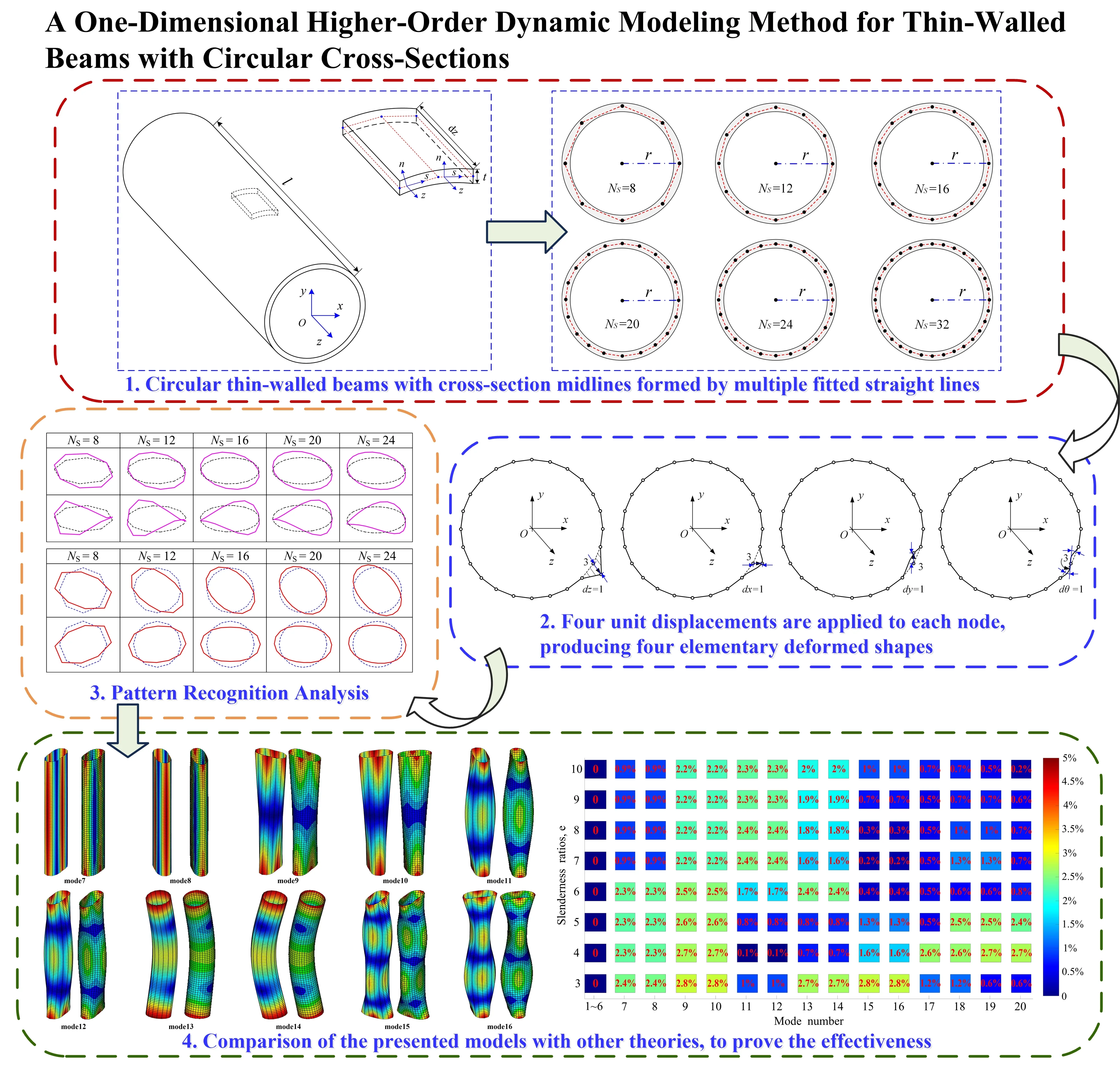
This paper addresses the construction of a dynamical model for a thin-walled beam with circular cross-section in the framework of one-dimensional higher-order beam theory. And a method for pattern recognition of circular thin-walled structures is proposed based on principal component analysis. Initially, a set of equal length linear segments are defined to discretize the mid-line of a circular section. Preliminary deformation modes of thin-walled structures, defined over the cross-section through kinematic concept, are parametrically derived through changing the discretization degree of the section. Next, the generalized eigenvectors are derived from the governing equations, and the characteristic deformation modes of circular sections with different discretization degrees are solved based on principal component analysis. In addition, a reduced higher-order model can be obtained by updating the initial governing equations with a selective set of cross-section deformation modes. The features include further reducing the number of degree of freedoms (DOFs) and significantly improving computational efficiency while ensuring accuracy. For illustrative purposes, the versatility of the procedure is validated through both numerical examples and comparisons with other theories.
Highlights
- A dynamic model of thin-walled beam with circle section is constructed base on 1D higher-order beam theory.
- The method relies on cross-section deformation data of thin-walled beams in free vibration.
- Further selection of deformation modes condenses DOFs of refined higher-order beam model.
- Examples verify the modeling accuracy and computation efficiency in dynamic analysis.
1. Introduction
Thin-walled structures are now widely used in many applications, such as civil engineering, automotive industry, aerospace and marine engineering, due to their low weight, high flexural capacity and easy fabrication [1]-[2]. Cylindrical thin-walled structures have higher compressive strength and better mechanical stability than traditional prismatic thin-walled structures. It is essential to develop a cylindrical thin-walled structural mechanics model with high accuracy and fast calculation speed.
In terms of simplifying calculations and improving efficiency, one-dimensional (beam) models have more advantages than two-dimensional (plate/shell) and three-dimensional (solid) approaches because they fit geometric dimensions, consider the ease of design and time cost, and also possess advantages in interpreting the structural response from the viewpoint of cross-section property. Although the static and dynamic behavior of a thin-walled beam structure can be accurately evaluated using two-dimensional shell elements, it is difficult to interpret its structural response from the viewpoint of the cross-section property [3]. To avoid unnecessary complexity in describing the beam response with precise three-dimensional methods, different simplified one-dimensional theories have been developed in the last decades [4]. Their list includes Euler-Bernoulli theory which is suitable for slender beams and Timoshenko theory by taking into account the effects of shear stress and rotary inertia. However, they all overlook significant section deformations of thin-walled beams, such as warping and distortion, and cannot accurately reflect the mechanical properties of thin-walled structures.
At present, a higher-order beam theory is used to appropriately reflect the effect of cross-section variation, by employing higher-order cross-section deformations as field variables. Three-dimensional displacements at a general point of a beam are approximated using cross-section shape functions and one-dimensional deformation field variables. By doing so, three-dimensional elasticity formulation can be reduced to a one-dimensional model. Since the early study by Vlasov on non-uniform warping is defined and used to refine the displacement field of thin-walled beams, many studies on higher-order beam theories have been carried out. For example, Kim and Kim [5] analytically derived the shape functions of the torsional and bending distortions for a rectangular cross section by assuming constant tangential displacement; Yoon et al. [6] present an efficient warping model for nonlinear elastoplastic torsional analysis of composite beam developed based on Benscoter warping theory; Shin et al. [7] newly derived section shape functions for composite thin-walled box beams for efficient structural analysis of composite thin-walled box beams; Nguyen et al. [8] proposed a beam frame modal approach based on higher-order beam theory for the analysis of thin-walled functionally graded straight and curved beams with general non-uniform polygonal cross-sections; Habtemariam et al. [9]-[10] established dynamic models of thin-walled pipes under different boundary conditions by taking into account deformation modes such as bending, warping, and torsion based on generalized beam theory (GBT).
Over past years, scholars have conducted extensive works on GBT, which originates from the work of Schardt [11], and has been extended into almost all fields of structural analysis of thin-walled beams [12]-[15]. GBT is an extension of the classic Vlasov beam theory, being presently well-established as an efficient, versatile, accurate and insightful approach to assess the structural behavior of prismatic thin-walled beams. Through decades of continuous refinement, GBT has been an efficient tool to perform buckling [16], post buckling [17] and dynamic analysis [18] of thin-walled beams in elasticity. Accordingly, many attempts have been made to extend GBT to the design and calculation of cylindrical thin-walled structures over the years. For example, Silvestre [19] proposed the assumption of partially overcoming null transverse extension and membrane shear strain by considering axisymmetric and torsion deformation modes; Basaglia et al. [20] evaluated the buckling analysis of cylindrical shells under a combination of axial compression and external pressure based on GBT; Peres et al. [21] proposed an extension GBT that enables the calculation of global-local bifurcation loads and associated buckling mode shapes, for thin-walled members with circular axis; de Miranda et al. [22], Gonçalves et al. [23], Muresan et al. [24] and Sahraei et al. [25] incorporated shear deformation effects into a GBT formulation for circular and prismatic thin-walled cross-section to improve displacement and stress field results.
In this paper, a dynamic model for a thin-walled structure considering circular cross-section characteristics is established based on one-dimensional higher-order dynamics theory. And a cross-section analysis procedure is proposed for the polygonal approximations of curved geometries. The preliminary deformation modes based on the displacement continuity condition are established on the cross-section mid-line and linearly superimposed to construct the three-dimensional displacement field. It is worth noting that a simple procedure is proposed to parameterize the degree of discretization when discretizing the mid-line of a circular section. The generalized matrix containing all modal information is derived from the governing equations, and then the main cross-section deformation modes of the one-dimensional higher-order model are identified by principal component analysis. In this aspect, principal component analysis takes particular advantage since it can directly extract deformation patterns hiding in free vibration behaviors, achieving dimension reduction with minimum information loss. Next, the identified deformation modes are compared and analyzed to determine the range of discretization that can accurately describe the dynamical behavior of circular thin-walled structures. Then, to further improve the computational efficiency, a reduced higher-order model can be obtained by updating the initial governing equations with a selective set of cross-section deformation modes. The resulted refined model possesses advantages not only in a minimum number of DOFs, but also from clear physical interpretation of the deformation modes coming from real structural behaviors. In practice, it fits the geometric dimensions of thin-walled beams, and takes into account the ease of design and analysis time cost.
2. Preliminary higher-order beam model
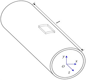
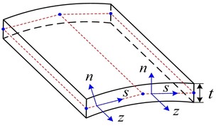
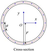
The preliminary higher-order beam model for cylindrical thin-walled structures is presented considering cross-section deformation. Specially, a set of equal length linear segments with the number of Ns is defined to discretize the mid-line of the circular section. For the sake of generality, a circular thin-walled beam whose cross-section mid-line is discretized into 16 equal-length straight segments shown in Fig. 1(a) and Fig. 1(c) is taken as an illustrative example, with the length of equal-length straight segments and the cross-sectional radius denoted by a and r, respectively, and the parameters l and t respectively represents the overall length and wall thickness of the circular thin-walled beam. The global and local coordinate systems are also shown (Fig. 1(a) and Fig. 1(b)). Where s being the coordinate along the mid-line, n indicating the perpendicular direction to the mid-line of the wall.
Fig. 1Circular thin-walled structure: a) the global coordinate system, b) the local coordinate system, and c) the discretization of the cross-section centerline with a series of nodes
a)
b)
c)
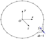
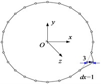
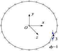
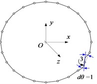
Correspondingly, 16 nodes are discretized on the mid-line of the thin-walled beam cross-section shown in Fig. 1(c), and axial, tangential, normal and torsional unit displacements are applied at each node. At the same time, the adjacent nodes are constrained to have zero displacement, resulting in four fundamental deformation modes for each node. For a better presentation, Fig. 2 shows four elementary deformed shapes obtained with unit displacements separately imposed on node 3.
2.1. Displacement field
According to one-dimensional higher-order theory, the displacement field d of the circular thin-walled structure cross-section is described by three components, namely u(s,z), v(s,z), w(s,z), which are expressed as:
where Na is the number of deformation modes considered, αi(s), φi(s), and ωi(s) are the deformation mode displacement components, and χi(z) are their amplitude functions along the beam length.
Fig. 2The elementary deformed shapes on node 3: a) the axial unit displacement, b) the tangential unit displacement, c) the normal unit displacement, and d) the torsional unit displacement
a)
b)
c)
d)
The three-dimensional displacement field of the thin-walled structure is expressed with three components U1(s,n,z), U2(s,n,z) and U3(s,n,z). By considering the membrane and flexural behaviors of thin walls, and employing Kirchhoff’s thin-plate assumption, the displacement field D can be obtained as:
Substitute Eq. (1) into Eq. (2), and the three-dimensional displacement field can be rewritten in a one-dimensional form by involving a transformation matrix H as:
In the case of ignoring defects and material uncertainties under the premise of small stress and by employing the Saint Venant-Kirchhoff material law, the strain field ε=[εzz(s,n,z),εss(s,n,z),γzs(s,n,z)]Τ and stress field σ=[σzz(s,n,z),σss(s,n,z),τzs(s,n,z)]Τ can be obtained as:
where C and E are the compatibility operator and the constitutive matrix, respectively, E and v are the material Young’s modulus and Poisson’s ratio, respectively.
2.2. Governing equations
The energy of the thin-walled beam includes strain energy U, potential energy W and kinetic energy T. In the absence of dissipative forces, the dynamical modeling of thin-walled structures involves the application of the Hamiltonian principle, reading:
where H is Hamiltonian, t1 and t2 are boundary times. The strain energy U, potential energy W and kinetic energy T are given by:
where V and ρ are the beam volume and the material density, respectively, p is the load component (including axial, tangential and normal components). The governing equation for the thin-walled structure is obtained by substituting Eqs. (3)-(5) and Eq. (7) into Eq. (6) as:
where A and L are the cross-section area and the beam length, respectively.
To facilitate the calculation, the finite element method is used to axially discretize χ, reading:
where N and X are the linear interpolation function and the node generalized displacement vector, respectively.
Substituting Eq. (9) into Eq. (8), the governing equation is reformulated as:
3. Identification of cross-section deformation modes
This section presents the concepts and procedures involved in the approach to perform cross-section deformation modes recognition, including the pre-processing of the data and the subsequent presentation of the recognition algorithms. In addition, a reduced higher-order model is proposed for practical applications.
3.1. Preparing cross-section deformation data
The eigenvectors of the higher-order model are the basis for recognizing deformation modes, which makes it necessary to extract and process the vibrational parameters prior to mode recognition. The generalized eigenvectors and generalized eigenvalues are obtained by solving Eq. (6) using the finite element method, and the generalized eigenvector matrix Γ contains all information about the deformation of the circular thin-walled structure. The data are pre-processed to obtain the characteristic deformation of thin-walled sections. By definition, Γ is given by:
where N0 is the number of interpolation nodes along the axial direction of the thin-walled cylindrical beam, Γk is the kth order generalized eigenvector and each eigenvector is a combination of the amplitude functions. Thus, Γk can be given by:
where Dn is the nth generalized eigenvalue.
The first Nmd pattern vectors are selected to compose a generalized feature vector matrix ˉΓ1 for pattern recognition, and matrix ˉΓ1 can be obtained by:
Reintegrate ˉΓ(n) into the form of ˉΓ(n)Δ, which can be given by:
Both out-of-plane and in-plane deformation modes are considered at any node j of the nth order modal vector. Thus, Γ(n)j(z) can be expressed as:
where Γj(out) and Γj(in) refer to the weight vectors corresponding to the out-of-plane and in-plane basis functions of node j, respectively.
Converting the first Nmd mode vectors into a matrix ˜Γ. And each column of the matrix ˜Γ represents a set of generalized displacements in the cross-section. By definition, ˜Γ is given by:
where fn is the intrinsic frequency of the nth order mode.
In order to facilitate the elimination of the interference of the extracted deformation patterns for subsequent recognition, ˜Γ is converted to the following form:
The effect of the extracted deformation pattern Ri on subsequent pattern recognition is eliminated by Schmitt orthogonalization and an updated matrix Γ(i) is given by:
where dot() is the inner product of Θi and Ri, Γ(i) denotes the matrix obtained after eliminating the main mode vector Ri. This equation eliminates the interference of Ri with subsequent recognition, and Ri consists of six classical shape vectors (Corresponding to α1~α3 in Fig. 5 and β1~β3 in Fig. 6, respectively).
Next, the generalized eigenvector matrix Γ is to be processed to identify cross-section deformation modes using the principal component analysis.
3.2. Recognition of basic algorithms
In this part, the principal component analysis is used to extract principal deformation patterns in the form of vectors. The elements of these vectors are virtually the coefficients of basis shape functions, which can be further used to mathematically describe cross-section deformation modes. Specifically, the cross-section deformation patterns hidden in the matrix Γ can be recognized through the principal component analysis, with Γ transformed into a low dimensional space and cross-section deformation modes ranked in clear hierarchy. According to the higher-order beam theory, in-plane and out-of-plane deformation modes are independently derived and described. Therefore, it is reasonable to decouple the amplitude matrix Γ into submatrix Γout consisting of out-of-plane nodal displacement values and Γin consisting of in-plane nodal displacement values. Thus, Γ can be rewritten as:
The amplitude matrices of the in-plane and out-of-plane basis functions are decentered separately to obtain the new matrices Aout and Ain, reading:
where (:,i) denotes all elements of column i of the matrix, j is the column element number, and m denotes the number of matrix rows.
The covariance matrices Cout and Cin are denoted as:
The eigenvectors are the extracted combined weight vector of basis functions. In this paper, the eigenvalues, used to measure the contribution of the eigenvectors, are arranged from largest to smallest as:
σ(k)in1≥σ(k)in2≥⋯≥σ(k)inr2,r2=rank(Γin).
3.3. Updating higher-order beam model
The number of cross-section characteristic deformations derived from pattern recognition is proportional to the number of discrete nodes in the cross-section. In engineering operations, too many section feature deformation modes will lead to model complexity and reduce calculational efficiency. According to the actual accuracy requirements of the model, cross-section characteristic deformation modes should be selected in order of priority to reduce the degrees of freedom and construct an improved one-dimensional higher-order model. In engineering practice, the greater the accuracy requirement, the greater the number of in-plane and out-of-plane characteristic deformations that need to be added. The original generalized coordinates are linearly superimposed and replaced by the selected cross-section feature deformations to form the new shape function vectors ˆα, ˆϕ and ˆω, which are given by:
where g and η denote the number of out-of-plane and in-plane characteristic deformation modes in the new combination of section characteristic deformations, respectively. ˆα, ˆϕ and ˆω are given by:
A new weight vector is introduced to describe the axial displacement variation of the thin-walled structure, ˆχ is given by:
The finite element implementation adopts the linear Lagrange interpolation and leads to ˆχ=NˆΧ. As a result, the updated governing equation can be obtained by substituting Eq. (27) into Eq. (10) as:
4. Numerical examples and discussion
The approach of cross-section analysis developed in this work is applied to circular thin-walled structures with different discretization degrees of the cross-section mid-line. Several illustrative examples are also provided to demonstrate the validity and accuracy of the improved higher-order models in this paper. They concern Convergence analysis, unconstrained structures and cantilevered structures.
4.1. Cross-section comparison analysis
In this section, pattern recognition is performed for circular thin-walled structures with different degrees of discretization in the midline of the cross-section. Specially, a set of equal length linear segments with the number of Ns is defined to discretize the mid-line of the circular section. The results for different degrees of discretization of the cross-section mid-line are shown in Fig. 3. Firstly, Ns=8 is chosen and the geometric dispersion is gradually increased, and the above-mentioned pattern recognition method is used to analyze and compare the section deformations. It can be proved that solutions for regular convex polygonal thin-walled structures gradually approaches those for circular thin-walled structure as the number of walls increases.
Fig. 3Results of different discretization degrees of cross-section midline
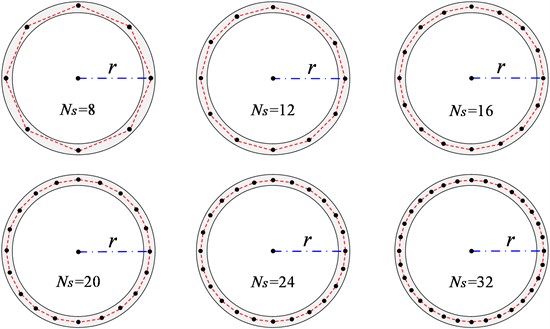
Fig. 4Elementary deformed shapes of thin-walled beam whose cross-section mid-line is discretized into 16 equal-length straight segments
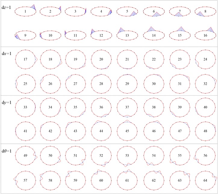
Prior to pattern recognition, the deformed shapes of the discrete cross section are described with basis shape functions αi(s), φi(s), and ωi(s). Take the cross-section discretized with Ns=16 nodes as shown in Fig. 1(c) as an example. Referring to a previous paper of Zhang [26], by imposing unit displacements on these nodes, it leads to 4×Ns=64 elementary deformed shapes as shown in Fig. 4. All the deformed shapes are employed to form the basis function set α, ϕ and ω for the preliminary higher-order beam model.
Pattern recognition of the first 60th order modal vectors of the model with different discretization degrees are performed using the method in this paper. The principal components with a cumulative contribution rate greater than 99.9 % are selected to identify the characteristic out-of-plane deformations of Ns with different degrees of discretization as shown in Fig. 5 and in-plane deformations as shown in Fig. 6. The cross-section deformation modes from α1 to α3 in Fig. 5 and β1 to β3 in Fig. 6 correspond to six rigid-body deformation modes in classical beam theory, respectively. Other modes are higher-order characteristic deformation modes of the cross-section, which demonstrate the mechanical properties of warping and distortion unique to thin-walled structures.
Fig. 5Out-of-plane characteristic deformation modes derived from Ns identification with different discretization degrees
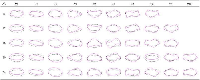
Fig. 6In-plane characteristic deformation modes derived from Ns identification with different discretization degrees
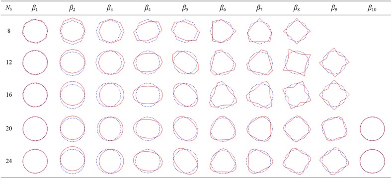
The two graphs show that the number of deformation modes increases with Ns. It is observed that the deformation mode shapes are virtually identical, irrespective of the Ns value adopted. The only visible difference is that the warping constant is significantly overestimated for coarse meshes but, as expected, a refined geometry discretization can markedly improve the accuracy, and the results tend asymptotically to the solutions for circular tubes.
However, the use of a refined discretization greatly increases the number of preliminary deformation modes and therefore reduces computational efficiency. To overcome this drawback, the characteristic deformations shown in Fig. 5 and Fig. 6 are selected for the construction of an improved one-dimensional higher-order model. For lower accuracy requirements, it is feasible to reproduce the classic Timoshenko beam by using only six rigid body deformation modes. For occasions with high accuracy requirements, a certain amount of in-plane and out of plane feature deformations can be added to achieve the required accuracy of the model.
4.2. Convergence analysis
In order to grasp the relationship between the accuracy and efficiency of the model, convergence analysis of the model is required to determine a reasonable number of discrete elements. A fixed constraint is applied to one end of the structure shown in Fig. 1 for convergence analysis. The beam model is discretized into different numbers of one-dimensional higher-order elements along the axial direction, and as shown in Fig. 7, relative errors of the first ten natural frequencies varied with the number of elements employed. The convergence data are obtained with 120 finite elements. It can be seen that at least 60 elements need to be discretized along the axial direction for the results of the beam model to converge.
Fig. 7Convergence of the first ten natural frequencies of the cantilevered thin-walled structure, varying with the number of employed finite elements

4.3. Grid independence verification
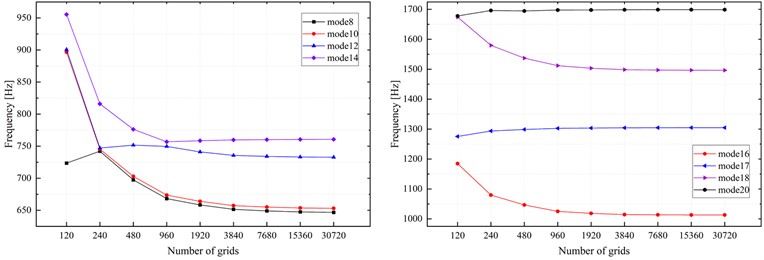
Since the accuracy of ANSYS shell theory calculations is affected by several factors, meshing stands out as a significant determinant. Therefore, the results obtained from ANSYS shell theory calculations need to be verified for mesh independence as necessary before comparison with the model presented in this paper. It should be noted that the thin-walled beams studied in this paper do not exhibit complex structures and have good consistency in the axial direction. Hence, it is only essential to keep the boundary conditions and loads unchanged, and to analyze the relationship between the sparseness of the mesh and the calculation results by gradually refining the mesh. The initial number of grids is set to 120 based on the model shown in Fig. 1(a), and then the grid elements are incrementally increased to observe the trend of the numerical solution. As shown in Fig. 8, it can be seen that at least 3840 grid elements need to be set for the result of the modal natural frequency no longer changing significantly.
4.4. Discretized error analysis
In order to verify the accuracy of the improved model in this paper relative to the circular thin-walled structure, the one-dimensional higher-order initial model and the reduced-dimensional model are applied to the free vibration analysis of the thin-walled structure. And the two sets of natural frequencies calculated are compared with those of circular thin-walled beams calculated by ANSYS shell theory.
Fig. 8Modal natural frequency varies with the number of employed grids
The models with different degrees of cross-section discretization are calculated by the finite element method, and the linear interpolation method is used to discretize the axial direction into 80 one-dimensional higher-order initial elements. The results are compared with the ANSYS shell model, which consists of 7680 shell elements, distributed as 120 along the length and 64 over the cross-section. Fig. 9 presents the relative errors about the natural frequencies of the first 20 modes. It should be pointed out that the relative errors are calculated based on the assumption that the results derived from ANSYS shell theory are accurate enough.
Fig. 9Comparison of the relative errors of the first 20 orders of natural frequencies of circular thin-walled structures with different degrees of discretization
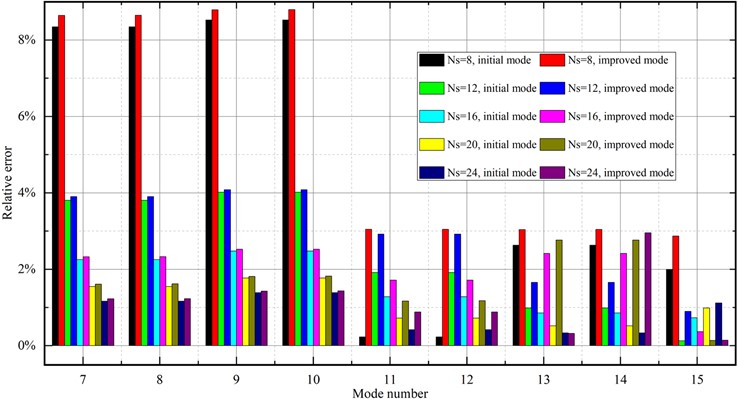
It is worth noting that the models with cross-section discretization of Ns=12 and above in Fig. 9 can obtain an equally modeling accuracy as that of 7680 two-dimensional shell units. The relative error is kept within 4 %. It is indicated that a regular convex polygonal thin-walled structure with cross-section discretization of more than 12 equal-length walls would be able to characterize well the variation of vibration patterns of circular thin-walled structures.
In addition, the improved higher-order model has an overall improvement in accuracy compared to the initial one-dimensional higher-order model. This is because the stiffness of the initial one-dimensional higher-order model reduces as the number of degrees of freedom considered increases, resulting in a lower natural frequency of the model. It is observed that the improved one-dimensional higher-order model not only further reduces the degrees of freedom, but also significantly improves computational efficiency. Accordingly, the calculational results of natural frequencies are more accurate as the stiffness of the model is increased to a certain extent. This data indicate that the improved one-dimensional higher-order model of this paper has greater potential.
4.5. Analysis of cantilever thin-walled structure
In order to verify that the theory of this paper is also applicable in modeling a thin-walled structure with different displacement constraints, numerical example is carried out on the cantilevered structure proposed in Section 4.2. Table 1 presents the natural frequencies of the first ten modes derived from the present model and the ANSYS shell theory, and their relative differences. Similarly, the results of the present model are obtained with 80 elements uniformly distributed along the axial direction. The ANSYS model consists of 7680 shell elements, 120 distributed along the length and 64 divided along the cross section.
Table 1Comparison of the first ten natural frequencies of the cantilevered thin-walled structure
Mode number | Present model | ANSYS shell | Relative error |
fi(Hz) | fAi  (Hz) (Hz) | δi  (%) (%) | |
1st | 127.85 | 132.58 | –3.57 |
2nd | 127.85 | 132.58 | –3.57 |
3rd | 640.74 | 652.29 | –1.77 |
4th | 655.68 | 652.57 | 0.48 |
5th | 655.68 | 652.57 | 0.48 |
6th | 667.72 | 675.80 | –1.20 |
7th | 667.72 | 675.80 | –1.20 |
8th | 725.91 | 720.57 | 0.74 |
9th | 725.91 | 720.57 | 0.74 |
10th | 959.45 | 979.60 | –2.06 |
As expected, the results in Table 1 show that the natural frequencies obtained with present model are very close to those from the ANSYS shell theory, with relative differences smaller than 4 % for the studied model. These facts prove that the present model could accurately reproduce three-dimensional behaviors of thin-walled structure.
4.6. Analysis of unconstrained thin-walled structure
An unconstrained thin-walled beam with circular cross-section shown in Fig. 1 (c) is considered for dynamic analyses so as to verify the performance of the proposed higher-order models. Related parameters of this thin-walled beam include length l=12 m, width of each arm a=0.04 m, thickness t=0.01 m, density ρ=7850 kg/m3, modulus of elasticity E=2×10¹¹ Pa, Poisson’s ratio v=0.3.
The free vibration shapes of the thin-walled structures of the improved one-dimensional higher-order model and ANSYS shell model are calculated, respectively. The comparisons of the 7th to 16th order free vibration shapes are shown in Fig. 10, and the results are divided into 10 pairs according to the order of vibration modes. In each pair, the left is derived from a modified one-dimensional higher-order model while the right represents the ANSYS shell models. There is no significant difference between the 10 pairs of vibration modes, which proves the excellent prediction capability of the improved one-dimensional higher-order model in this paper for the three-dimensional vibration modes of circular thin-walled structures.
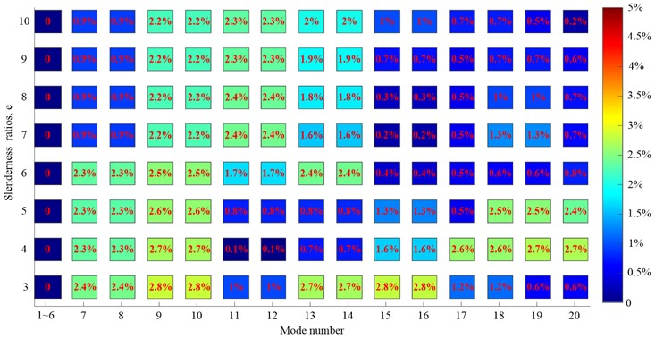
To further illustrate the applicability of the improved one-dimensional higher-order model in this paper, the thin-walled structure shown in Fig. 1 is used for numerical analysis of circular thin-walled structures with different slenderness ratios. Fig. 11 presents the relative errors of natural frequencies for thin-walled structures with a slenderness ratio ranging from 3 to 10 based on the shell model. It is observed that the calculational accuracy of the natural frequencies of thin-walled structures improves as the slenderness ratio increases. The relative error of natural frequencies is kept within 2.8 % despite the slenderness ratio is 3. It indicates that the improved one-dimensional higher-order model in this paper can be applied to the dynamic modeling of circular cross-section thin-walled structures with a slenderness ratio of more than 3, and has a wider application range than classical beam theories.
Fig. 10Comparison of free vibration modes between improved one-dimensional higher-order model and ANSYS shell model
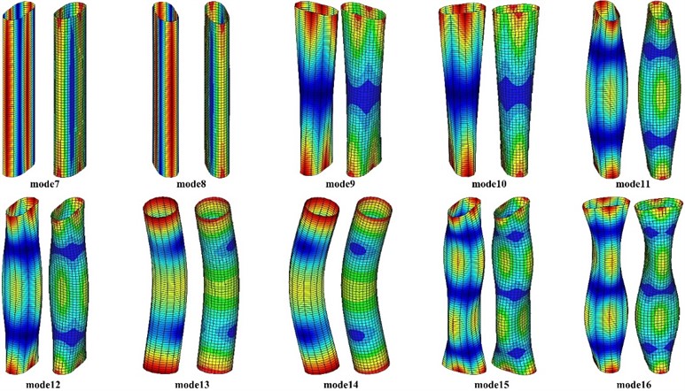
Fig. 11Comparison of the first 20 natural frequencies of thin-walled structures with different slenderness ratios between the improved one-dimensional higher-order model and the ANSYS shell model
5. Conclusions
In this paper, the dynamics model of thin-walled structure with circular cross-section is constructed based on one-dimensional higher-order beam theory, and the cross-section characteristic deformation modes are extracted on this basis using the principal component analysis. With a compact set of cross-section deformation modes employed, the preliminary one-dimensional model was updated to the refined beam model of high precision and efficiency. A simple procedure is proposed to implement the parameterization of the degree of discretization and it is based on the discretization of a set of equal-length linear segments in the cross-section mid-line, which avoids the difficulties related to GBT formulations for genuinely curved sections. The basic idea is to obtain the deformation modes by increasing the discretization degree to approximate the cross-section geometry. The following conclusions and suggestions have been drawn.
1) The characteristic deformation modes of circular thin-walled structures can be efficiently recognized and extracted by using the principal component analysis.
2) A refined discretization makes it possible to accurately describe the three-dimensional dynamical properties of circular thin-walled structures.
3) To ensure the accuracy of the established circular thin-walled dynamics model, at least 60 one-dimensional high-order elements should be utilized in order to achieve good convergence.
4) The refined higher-order beam model is valid for thin-walled beams with various boundary conditions and slenderness ratios, justifying the applicability of the proposed approach.
5) The refined higher-order beam model is able to accurately predict dynamic behaviors of thin-walled beams with much higher computation efficiency comparing with plate/shell theory.
References
-
M. Rezaiee-Pajand, A. R. Masoodi, and E. Arabi, “Improved shell element for geometrically non-linear analysis of thin-walled structures,” Proceedings of the Institution of Civil Engineers – Structures and Buildings, Vol. 175, No. 4, pp. 347–356, Apr. 2022, https://doi.org/10.1680/jstbu.19.00130
-
Q. Wu, H. Gao, Y. Zhang, and L. Chen, “Dynamical analysis of a thin-walled rectangular plate with preload force,” Journal of Vibroengineering, Vol. 19, No. 8, pp. 5735–5745, Dec. 2017, https://doi.org/10.21595/jve.2017.18330
-
H. Kim and G.-W. Jang, “Higher-order thin-walled beam analysis for axially varying generally shaped cross sections with straight cross-section edges,” Computers and Structures, Vol. 189, pp. 83–100, Sep. 2017, https://doi.org/10.1016/j.compstruc.2017.04.015
-
V. Adámek, “The limits of Timoshenko beam theory applied to impact problems of layered beams,” International Journal of Mechanical Sciences, Vol. 145, pp. 128–137, Sep. 2018, https://doi.org/10.1016/j.ijmecsci.2018.07.001
-
Y. Kim and Y. Y. Kim, “Analysis of thin-walled curved box beam under in-plane flexure,” International Journal of Solids and Structures, Vol. 40, No. 22, pp. 6111–6123, Nov. 2003, https://doi.org/10.1016/s0020-7683(03)00367-6
-
K. Yoon, P.-S. Lee, and D.-N. Kim, “An efficient warping model for elastoplastic torsional analysis of composite beams,” Composite Structures, Vol. 178, pp. 37–49, Oct. 2017, https://doi.org/10.1016/j.compstruct.2017.07.041
-
D. Shin, S. Choi, G.-W. Jang, and Y. Y. Kim, “Higher-order beam theory for static and vibration analysis of composite thin-walled box beam,” Composite Structures, Vol. 206, pp. 140–154, Dec. 2018, https://doi.org/10.1016/j.compstruct.2018.08.016
-
T.-T. Nguyen, N.-L. Nguyen, J. Lee, and Q.-H. Nguyen, “Vibration analysis of thin-walled functionally graded sandwich beams with non-uniform polygonal cross-sections,” Composite Structures, Vol. 278, p. 114723, Dec. 2021, https://doi.org/10.1016/j.compstruct.2021.114723
-
A. K. Habtemariam, C. Könke, V. Zabel, and M. J. Bianco, “Generalized beam theory formulation for thin-walled pipes with circular axis,” Thin-Walled Structures, Vol. 159, p. 107243, Feb. 2021, https://doi.org/10.1016/j.tws.2020.107243
-
A. K. Habtemariam, F. Tartaglione, V. Zabel, C. Könke, and M. J. Bianco, “Vibration analysis of thin-walled pipes with circular axis using the generalized beam theory,” Thin-Walled Structures, Vol. 163, p. 107628, Jun. 2021, https://doi.org/10.1016/j.tws.2021.107628
-
R. Schardt, “Lateral torsional and distortional buckling of channel – and hat-sections,” Journal of Constructional Steel Research, Vol. 31, No. 2-3, pp. 243–265, Jan. 1994, https://doi.org/10.1016/0143-974x(94)90012-4
-
J. M. Davies and P. Leach, “First-order generalised beam theory,” Journal of Constructional Steel Research, Vol. 31, No. 2-3, pp. 187–220, Jan. 1994, https://doi.org/10.1016/0143-974x(94)90010-8
-
N. Silvestre, D. Camotim, and N. F. Silva, “Generalized beam theory revisited: from the kinematical assumptions to the deformation mode determination,” International Journal of Structural Stability and Dynamics, Vol. 11, No. 5, pp. 969–997, Nov. 2011, https://doi.org/10.1142/s0219455411004427
-
R. Gonçalves, M. Ritto-Corrêa, and D. Camotim, “A new approach to the calculation of cross-section deformation modes in the framework of generalized beam theory,” Computational Mechanics, Vol. 46, No. 5, pp. 759–781, Jul. 2010, https://doi.org/10.1007/s00466-010-0512-2
-
A. D. Martins, D. Camotim, R. Gonçalves, and P. B. Dinis, “Enhanced geometrically nonlinear generalized beam theory formulation: derivation, numerical implementation, and illustration,” Journal of Engineering Mechanics, Vol. 144, No. 6, p. 04018, Jun. 2018, https://doi.org/10.1061/(asce)em.1943-7889.0001457
-
R. Bebiano, C. Basaglia, D. Camotim, and R. Gonçalves, “GBT buckling analysis of generally loaded thin-walled members with arbitrary flat-walled cross-sections,” Thin-Walled Structures, Vol. 123, pp. 11–24, Feb. 2018, https://doi.org/10.1016/j.tws.2017.10.045
-
A. W. Ruggerini, A. Madeo, R. Gonçalves, D. Camotim, F. Ubertini, and S. de Miranda, “GBT post-buckling analysis based on the implicit corotational method,” International Journal of Solids and Structures, Vol. 163, pp. 40–60, May 2019, https://doi.org/10.1016/j.ijsolstr.2018.12.011
-
R. Bebiano, R. Calçada, D. Camotim, and N. Silvestre, “Dynamic analysis of high-speed railway bridge decks using generalised beam theory,” Thin-Walled Structures, Vol. 114, pp. 22–31, May 2017, https://doi.org/10.1016/j.tws.2017.01.027
-
N. Silvestre, “Generalised beam theory to analyse the buckling behaviour of circular cylindrical shells and tubes,” Thin-Walled Structures, Vol. 45, No. 2, pp. 185–198, Feb. 2007, https://doi.org/10.1016/j.tws.2007.02.001
-
C. Basaglia, D. Camotim, and N. Silvestre, “GBT-based buckling analysis of steel cylindrical shells under combinations of compression and external pressure,” Thin-Walled Structures, Vol. 144, p. 106274, Nov. 2019, https://doi.org/10.1016/j.tws.2019.106274
-
N. Peres, R. Gonçalves, and D. Camotim, “Generalised beam theory formulation for the buckling analysis of thin-walled members with circular axis,” Thin-Walled Structures, Vol. 176, p. 109322, Jul. 2022, https://doi.org/10.1016/j.tws.2022.109322
-
S. de Miranda, A. Gutiérrez, R. Miletta, and F. Ubertini, “A generalized beam theory with shear deformation,” Thin-Walled Structures, Vol. 67, pp. 88–100, Jun. 2013, https://doi.org/10.1016/j.tws.2013.02.012
-
R. Gonçalves, R. Bebiano, and D. Camotim, “On the shear deformation modes in the framework of generalized beam theory,” Thin-Walled Structures, Vol. 84, pp. 325–334, Nov. 2014, https://doi.org/10.1016/j.tws.2014.07.012
-
A.-A. Muresan, M. Nedelcu, and R. Gonçalves, “GBT-based FE formulation to analyse the buckling behaviour of isotropic conical shells with circular cross-section,” Thin-Walled Structures, Vol. 134, pp. 84–101, Jan. 2019, https://doi.org/10.1016/j.tws.2018.07.032
-
A. Sahraei, P. Pezeshky, S. Sasibut, F. Rong, and M. Mohareb, “Finite element formulation for the dynamic analysis of shear deformable thin-walled beams,” Thin-Walled Structures, Vol. 173, p. 108989, Apr. 2022, https://doi.org/10.1016/j.tws.2022.108989
-
L. Zhang, W. Zhu, and A. Ji, “Application of pattern recognition to the identification of cross-section deformation modes of thin-walled structures,” IEEE Access, Vol. 7, pp. 169586–169598, Jan. 2019, https://doi.org/10.1109/access.2019.2954712
About this article
This work was supported by the National Key Research and Development Program (Grant No. 2022YFB4703401).
The datasets generated during and/or analyzed during the current study are available from the corresponding author on reasonable request.
Tao Zeng: writing–original draft preparation and visualization. Lei Zhang: methodology and writing-review and editing. Yuhang Zhu: formal analysis and investigation.
The authors declare that they have no conflict of interest.

