Abstract
Form function matrix is created by introducing high order displacement interpolation function in the node. Based on the virtual work principle and dynamic finite element theory, the spatial element stiffness matrix, mass matrix and earthquake mass matrix of a thin-walled box girder having 9 freedom degrees at each node are deduced. The D’Alembert vibration equation is also established. Newmark- method is used through MATLAB to solve the seismic response of a long-span continuous curved box girder bridge under El-centro seismic waves. Meanwhile the spatial finite element model of the whole bridge is established by ANSYS. The results indicate that the dynamic responses of pier columns exhibit spatiality. The dynamic response of a bridge structure under 2D coupling horizontal seismic excitation is much bigger than that under 1D horizontal seismic excitation. The critical angle of seismic waves is 50° for radial displacement response. Theoretical calculation results are in agreement with the finite element analysis results. The deduced element matrix not only can be used to calculate the seismic response of long-span curved beam bridge structures but also can provide significant references for the structures in vibration response caused by moving traffic.
Highlights
- The element stiffness matrix, mass matrix and earthquake mass matrix of the thin-walled box girder are deduced.
- Four loading working conditions of seismic action are considered.
- The critical angle of seismic action is researched.
1. Introduction
Thin-walled box girder is widely used in bridge structures. Spatial mechanical behavior of thin-walled box girder is complex, as the fundamental deformation include vertical bending and shear lag [1, 2] under symmetrical loads. In addition, there are torsion and distortion effects [3, 4] when vehicle eccentric loads are imposed. However, for thin-walled curved box girder, coupling deformation prevails in terms of bending, torsion, warping, distortion and shear lag, regardless of whether the load is symmetric or not. Hence, the complex mechanical behavior of thin-walled box girder needs to be further investigated.
Based on the stiffness method, spatial element stiffness matrix and stiffness equation of a straight box girder having 10 freedoms at each node were deduced [5], in which the restricted torsion, distortion and shear lag effect were considered. According to the finite element theory, spatial element stiffness matrix of a thin-walled curved box girder having 14 freedoms at each node was proposed [6], the compression-tension, bending, torsion, warping, distortion and shear lag effect were considered. Zheng et al. [7] established an elastic governed differential equation of thin-walled curved beam and obtained the exact analytic solution, the bending torsion warping, distortion and shear lag effect were considered. It can be seen that these researches have improved the static load analysis theory of thin-walled box girder.
Earthquakes have brought great damages to the bridge structures, therefore it is imperative to study the dynamic characteristics and seismic responses of box girder bridges. Based on the generalized coordinate method and energy principle, Chan et al. [8] deduced the vibration governed differential equation of curved bridges and provided the explicit stiffness matrix and mass matrix, whilst the distortion and shear lag effect were neglected. Hugo et al. [9] studied the vibration characteristics of a curved box girder bridge under vehicle load by field experiments. Taysi et al. [10] explored the elastic free vibration of a box girder bridge by the finite strip method and automatic mesh generated technology. Zhou et al. [11] deduced the differential equations and corresponding boundary conditions of a steel-concrete composite continuous box girder based on Hamilton principle. Ji et al. [12] extended the calculation of free vibration characteristics of a thin-walled box girder to a composite box girder with corrugated steel webs. Chen et al. [13] investigated the effects of higher modes on the seismic performance of tall-pier bridges by shaking table test. Tubaldi E. et al. [14] studied the influence of both axial load and higher-order modes on the dynamic behavior and seismic response of slender bridge piers by an analytical formulation and a continuous model. Elkady et al. [15] carried out an experimental research on the behavior of a typical cable-stayed bridge subjected to lateral earthquake excitation. Base on the similarity principle and multi-point excitation theory, Chen et al. [16, 17] investigated the seismic responses of irregular high piers curved bridges by shaking table test, the different spectral seismic wave, peak ground acceleration and local site effect were considered. Soyluk K. [18], Nuti C. [19] and Lupoi A. [20] studied the seismic response of long-span curved girder bridge under multi-point excitation by experiment.
The aforementioned researches have improved dynamic investigation of curved box girder bridges. However, for the dynamic characteristics, most of the concerned researches obtained the self-vibration characteristics of a box girder by energy variation principle and acquired the dynamic characteristics through solving high order differential equations, which consequently leads to a complicated calculation. Furthermore, most of the concerned research objects were straight box girder for simplicity rather than the curved box girder. As for seismic response, the current research efforts lie within the qualitative analysis of the seismic response of curved bridge by finite element method and experimental method, whilst there is a lack of quantitative calculation in the theory. Therefore, this paper attempts to provide a quantitative analysis to fill the theoretical blank in this filed. The element stiffness matrix, mass matrix and earthquake mass matrix of the thin-walled box girder are proposed in present work. The characteristic equations and D’Alembert vibration equation of a curved box girder bridge are deduced by assembling element matrix. Furthermore, eigenvalue function and Newmark-β method are used through MATLAB to solve the characteristic equation and seismic response of box girder bridges.
2. Element matrix
2.1. Fundamental assumption
In order to simplify the spatial mechanical model of a curved box girder, the following assumptions are to be made:
(1) Material is of linear elastic.
(2) Distortion and warping of box girder are not considered.
(3) The size of curved box girder cross section is of small magnitude compared with its length and curvature radius.
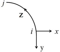
Curved box girder is shown as Fig. 1, , , are respectively represent transverse, vertical and longitudinal direction, element node displacement is shown as follows:
where , are node serial numbers, , , are respectively longitudinal, vertical and transverse displacement, , , are respectively torsion angle, vertical angle and transverse angle, is transverse curvature, is restricted distortion displacement, is maximum shear displacement, this parameter is necessary for considering shear lag effects.
Fig. 1Curved box girder
2.2. Stiffness matrix
According to the geometric equation of elastic mechanic, generalized strainis given by:
The matrix form is shown as follows:
where the first matrix-vector in the right side is differential operator , the second matrix-vector is generalized displacement vector , therefore, it can be denoted as .
Transverse displacement is interpolated by fifth polynomial, vertical displacement and torsion angle are interpolated by third polynomial, longitudinal displacement is interpolated by linear interpolation [21], therefore, the form function matrix can be obtained.
The displacement of the element can be obtained from the following equation:
where is the element node displacement. Subsequently, Eq. (3) is substituted into Eq. (4), the following equations can be obtained:
here, , is strain matrix, elastic matrix is given by:
where , are elastic modulus and shear modulus, , are vertical and transverse inertial moment, , are free torsion and restraint torsion inertial moment. The stress in the element is shown as follows:
The virtual strain of element is given by:
The work done by the stress for the virtual strain is shown as follows:
Meanwhile, the work done by the nodal force for a virtual displacement is shown as follows:
According to the virtual work principle [22], the nodal force column matrix can be obtained when the equation is substituted into Eq. (9) and Eq. (10):
The element matrix is obtained from Eq. (11) and it is shown as follows:
2.3. Mass matrix
Considered that the mass center does not coincide with the torsion center in the box girder cross section, the transverse inertial force of box girder is given by:
where is the density of box girder, is the distance from the mass center to the torsion center. The transverse inertial force will also contribute to an additional torsion moment, which is given by:
here, is the polar inertia moment, all inertia forces of box girder are shown as follows:
The corresponding matrix form is shown as follows:
where the first matrix-vector in the right side is denoted as matrix . Substituting the equation into Eq. (16) results in:
The equivalent nodal force is given by:
Substituting Eq. (18) into Eq. (17) results in:
The mass matrix can be obtained from Eq. (19) and it is shown as following equations:
2.4. Earthquake mass matrix
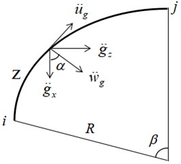
As is shown in Fig. 2, the ground acceleration is decomposed in 3 directions and it is given by:
Seismic action of curved box girder is given by:
Fig. 2Decomposition of ground acceleration
Substituting Eq. (22) into Eq. (23) results in:
where the third term of the right side is denoted as matrix , therefore equivalent seismic action of the element is given by:
According to Newton’ second law, earthquake mass matrix is shown as follows:
There is a geometrical relationship in Fig. 2:
Then, the following equations can be obtained:
Eq. (28) is expanded based on Taylor series (only the first two entries are used), the earthquake mass matrix can be obtained when substituting Eq. (28) into Eq. (26):
3. Application and analysis
3.1. Free vibration characteristics
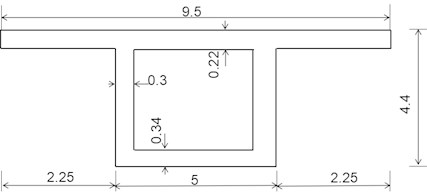
A PC continuous curved box girder bridge with three spans is shown as Fig. 3. The longitudinal span is of 210 m, curvature radius 300 m, elasticity modulus 3.4×10⁶ MPa, density 2500 kg/m3. The cross section size of box girder is shown as Fig. 4.
Fig. 3Three-span curved box girder bridge (Unit: m)
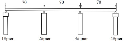
Fig. 4Cross section size of box girder (Unit: m)
Vibration equation of curved box girder bridge is shown as follows:
where is vibration frequency, Eq. (30) has a nonzero solution when the curved box girder bridge vibrates freely, the following equations can be obtained:
The vibration frequency can be acquired when introducing corresponding boundary conditions according to Eq. (31). Attention should be paid that flow cylindrical coordinate system is adopted in the present work, therefore it is unnecessary to transform the element matrix.
The mesh of the curved box girder bridge along the longitudinal direction at each span contains 2, 3 and 4 elements, respectively and the eigenvalue equation is solved through MATLAB. Meanwhile, a finite element model is established by ANSYS, the primary beam is simulated by SHELL 63 element and the piers are simulated by SOLID 45 element, TARGE170 3D element and CONTA175 element are used to simulate the supports. There are totally 9660 elements and 9706 nodes in the finite element model. According to Chinese code JTG D60-2015 [23], estimation formulas of the natural vibration frequency of continuous beam bridge are shown as following equations:
where is the span , are elastic modulus and inertia moment is linear mass , are the first 2th order frequencies. Theoretical value and ANSYS results are shown in Table 1 and Fig. 5.
Table 1Vibration frequency of continuous curved box girder bridges (Hz)
Order | Theoretical results | ANSYS | Vibration model | ||
2 element | 3 element | 4 element | |||
1 | 1.911 | 1.914 | 1.914 | 1.949 | Vertical vibrates |
2 | 2.338 | 2.348 | 2.349 | 2.431 | Vertical vibrates |
3 | 2.481 | 2.504 | 2.508 | 2.649 | Transverse vibrates |
4 | 2.716 | 2.77 | 2.796 | 2.835 | Transverse vibrates |
5 | 2.977 | 3.024 | 3.051 | 3.059 | Torsional vibrates |
Fig. 5Influence of element number on error
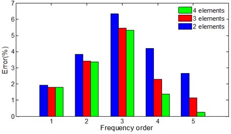
From Table 1, the theoretical values present a good agreement with the ANSYS numerical results, satisfied results can be obtained when each span of the whole bridge is meshed with 3-4 elements, the computing time is greatly reduced compared with ANSYS. However, the first 2th order frequency calculated by JTG D60-2015 [23] are 3.184 Hz, 5.531 Hz respectively, giving a respective discrepancy of 63.4 % and 127.5 % in comparison to the numerical results from ANSYS, which will lead to a larger positive bending moment at mid-span and make larger negative bending moment at support when the vehicle impact effects are considered. Besides, the first 2th order vibration models of the bridge are vertical vibration, the 3th and 4th order models are transverse vibration. It means vertical stiffness of long-span curved box girder bridge is smaller compared with its transverse stiffness. The torsional vibration is firstly occurred in the 5th order vibration model, which means the bridge has good torsion resistance.
In Fig. 5, the errors between theoretical values and ANSYS are smaller and smaller with the increasing of element numbers, this trend is more obvious for high order frequencies.
3.2. Seismic responses calculation
Rayleigh linear damping is adopted in present work, therefore D’ Alembert vibration differential equation of the bridge structure is given by:
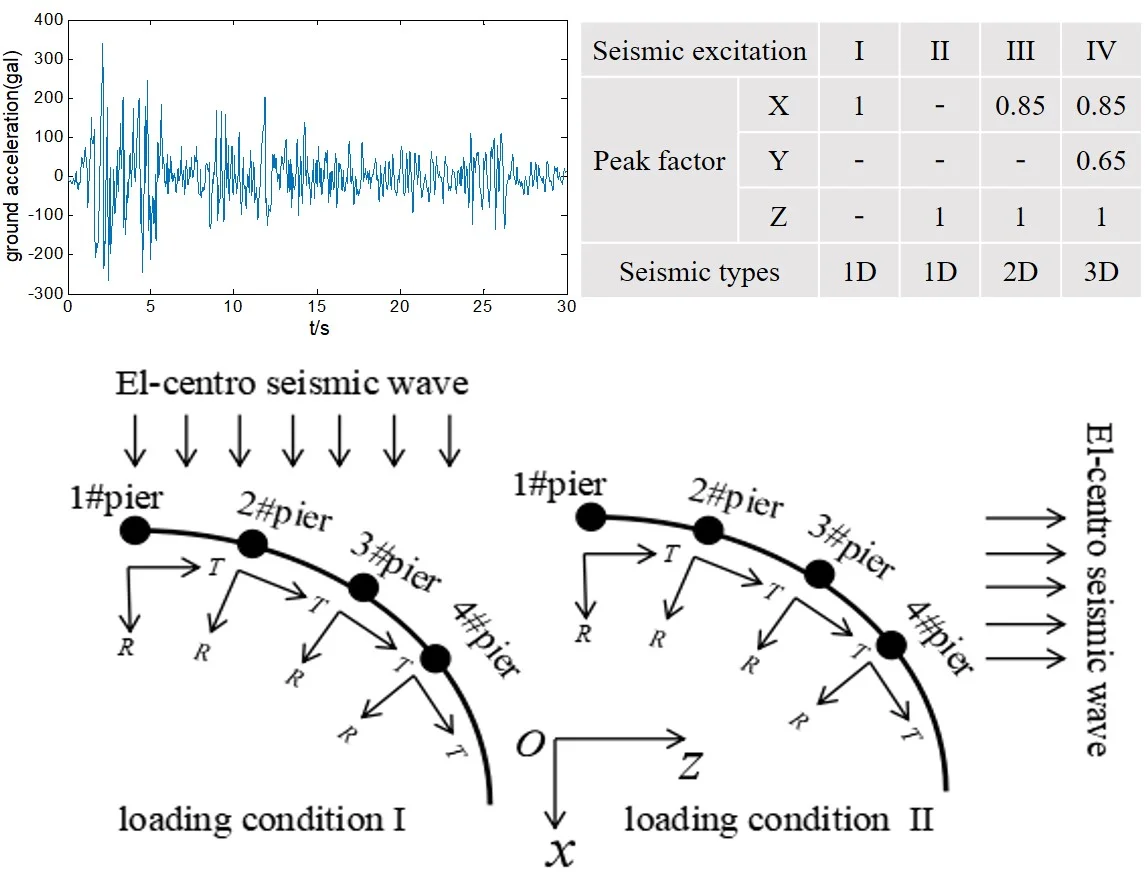
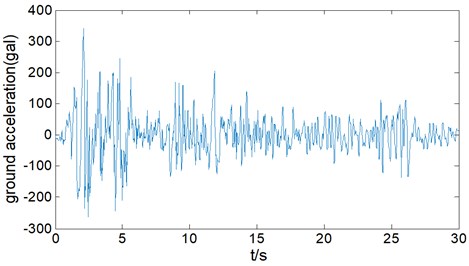
The Newmark-β method [24] is adopted to obtain the seismic response. El-Centro seismic waves (north-south component) is chosen as earthquake excitation in present work as shown in Fig. 6.
Fig. 6El-Centro seismic waves (north-south component)
Generally, 1D horizontal seismic action (longitudinal direction or transverse direction) and 2D horizontal seismic action are mainly considered in bridge seismic resistance. However, vertical seismic action should be also considered for the long-span curved box girder bridge. 4 loading conditions are set in present work as shown in Table 2, peak factor in different directions are set up as 1 (horizontal direction1), 0.85 (horizontal direction 2) and 0.65 (vertical direction).
Table 2Loading conditions of seismic excitation
Seismic excitation | I | II | III | IV | |
Peak factor | 1 | – | 0.85 | 0.85 | |
– | – | – | 0.65 | ||
– | 1 | 1 | 1 | ||
Seismic types | 1D | 1D | 2D | 3D | |
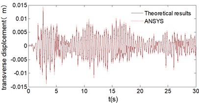
Dynamic responses at 1# pier top under loading condition I are shown as Fig. 7. It can be seen from Fig. 7 that the theoretical results agree well with the finite element results of ANSYS. Based on it, peak dynamic response of all piers under 4 loading conditions are also calculated and the results are shown as Fig. 8, Fig. 9 and Fig. 10.
In Fig. 8(c), Radial acceleration of 1# pier and 4# are 906 gal and 816 gal respectively under transverse horizontal seismic action (loading condition I), while they are 919 gal and 1063 gal respectively under longitudinal horizontal seismic action (working condition II), it indicates that continuous curved box girder bridge is likely to be damaged by transverse girder-falling at both ends under 1D horizontal seismic action. In Fig. 8(a) and Fig. 8(c), radial displacement and acceleration of 4# pier are 18.5 mm and 1063 gal under longitudinal horizontal seismic action, while they are 28.9 mm and 1640 gal under 2D horizontal loading(working condition III), the increasing rates are 56.2 % and 54.3 %, which means peak dynamic response under 2D coupling horizontal seismic action is greater than that under 1D horizontal seismic action. In addition to the 1D horizontal seismic action (transverse or longitudinal direction) during bridge seismic design, an adverse effect of 2D coupling horizontal seismic action should also be considered. Furthermore, peak dynamic response of the curved box girder bridge under 3D seismic action (working condition IV) is almost the same as that under 2D horizontal seismic action, which indicates that vertical seismic action isn’t coupled with horizontal seismic action.
Fig. 7Dynamic response of 1# pier
a) Displacement
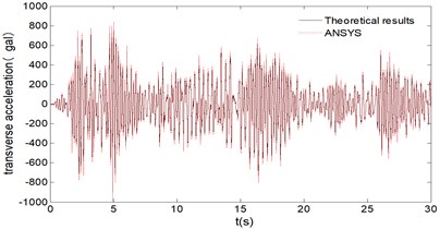
b) Acceleration
Fig. 8Dynamic responses under different loading conditions
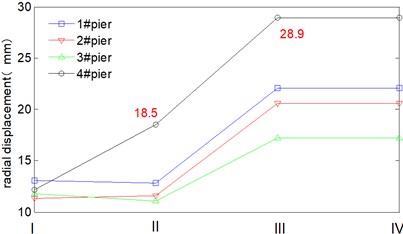
a) Radial displacement
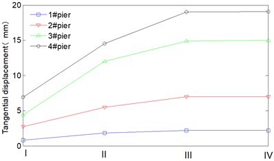
b) Tangential displacement
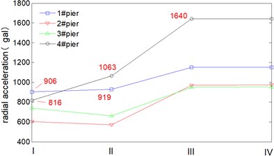
c) Radial acceleration
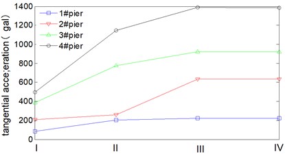
d) Tangential acceleration
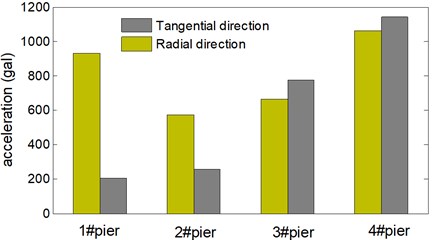
In Fig. 9, radial dynamic responses of all piers are greater than tangential dynamic responses under transverse horizontal seismic action. In Fig. 10, radial dynamic responses of 1# and 2# pier are also greater than tangential dynamic responses under longitudinal seismic action, whilst for 3# pier and 4# pier, their radial dynamic responses are basically equal to their tangential dynamic responses, it indicates that the continuous curved box girder bridge mainly vibrates along transverse direction together with in-plane rotation around 3# pier and 4# pier.
Seismic wave direction of loading condition I and II are shown as Fig. 11, and represents the radial direction and tangential direction respectively. Flow cylindrical coordinate system is adopted in the present work, therefore seismic wave direction of loading condition I is exactly coincident with the radial direction of 1# pier, the angle between them is denoted as 0°. Seismic wave direction of loading condition II is also exactly coincident with the tangential direction of 1# pier, the angle between them is denoted as 90°. There is a certain angle between seismic wave direction and radial direction (or tangential direction) for the rest piers. Under loading condition I, radial responses of each pier are basically equal. Whilst the tangential responses of each pier differ greatly and present obvious spatiality under loading condition II. Besides, the peak displacement doesn’t occur at 1# pier but 4# pier, the radial and tangential displacement are respectively 18.5 mm, 14.5 mm. It indicates that mechanics behavior of the continuous curved box girder bridge is so complicated, and the peak responses may not occur along seismic wave direction.
Fig. 9Dynamic response of the bridge under loading condition I
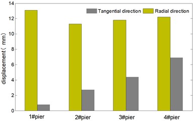
a) Displacement
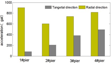
b) Acceleration
Fig. 10Dynamic responses of the bridge under loading condition II
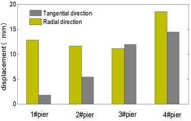
a) Displacement
b) Acceleration
Fig. 11Seismic wave direction of loading condition I and II
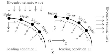
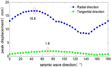
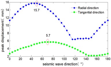
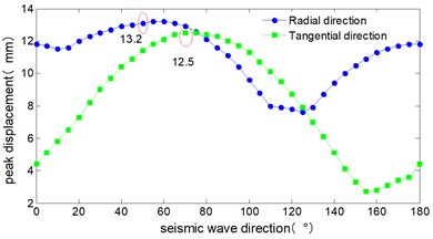
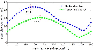
Seismic waves at any direction in the horizontal plane can be decomposed along and direction, so there is certainly a critical angle that make the curved box girder bridge reach its peak displacement responses. In order to investigate the critical angle of seismic wave and acquire the peak dynamic response in the range of 0° to 180°, 5° is set as the increment in present work.
The critical angle of seismic wave is shown as Fig. 12, the peak displacement response of all piers roughly change in sine wave form in the range of 0° to 180°. Both the radial and tangential peak displacements appeared for all the 4 piers as the seismic wave angle reached at 50° and 70°. The radial peak displacements are 16.8 mm, 15.7 mm, 13.2 mm, 22.1 mm respectively, and the tangential peak displacements are 1.9 mm, 5.7 mm, 12.5 mm, 15.5 mm respectively.
Fig. 12Critical angle of seismic wave
a) 1# pier
b) 2# pier
c) 3# pier
d) 4# pier
4. Conclusions
Element stiffness matrix, mass matrix and earthquake mass matrix of curved box girder bridge are deduced in present work, vibration characteristics and seismic waves of a long-span curved box girder bridge are solved by eigenvalue function and Newmark- method, the following conclusions can be draw:
1) The theoretical results present a good agreement with the finite element analysis, which can verify the accuracy and reliability of the deducing element matrix. Besides, satisfied results can be acquired when the curved box girder bridge is meshed with several elements, which shows the high efficiency of the proposed method in the present work.
2) In addition to the 1D horizontal seismic action during bridge seismic design, an adverse effect of 2D coupling horizontal seismic action should also be considered.
3) Long-span curved box girder bridges have a large transverse seismic response, they are likely to be damaged by the transverse girder-falling at both ends under 1D horizontal seismic action.
4) Spatial mechanical behavior of long-span curved box girder bridges is complicated; the peak responses may not occur along seismic wave direction.
5) For long-span curved box girder bridges, the vertical seismic action isn’t coupled with horizontal seismic action and it can be calculated separately.
6) The deducing element matrix not only can calculate the seismic response of long-span curved box girder bridges but also can provide significant references for vehicle-bridge coupling vibration response.
References
-
Reissner E. Analysis of shear lag in box beams by the principle of the minimum potential energy. Quarterly of Applied Mathematical, Vol. 4, Issue 3, 1946, p. 268-278.
-
Dezi L., Mentrasti L. Nonuniform bending-stress distribution (shear lag). Journal of Structural Engineering, Vol. 111, Issue 12, 1985, p. 2675-2690.
-
Jonsson J. Distortional theory of thin-walled beams. Thin-Walled Structures, Vol. 33, Issue 4, 1999, p. 269-303.
-
Xu Xun, Qiang Shizhong Theoretical research on distortion analysis of thin-walled box girder. Engineering Mechanics, Vol. 30, Issue 11, 2013, p. 192-201, (in Chinese).
-
Xie Xu, Huang Jianyuan Three dimensional analysis for warping distortion and shear lag effect of thin-walled box girder bridge under restrained torsion. China Civil Engineering Journal, Vol. 28, Issue 4, 1995, p. 3-14, (in Chinese).
-
Wei Chenglong, Zeng Qinyuan A new element for thin-walled curved box girder analysis including warping distortion and shear lag effects. China Civil Engineering Journal, Vol. 33, Issue 6, 2000, p. 82-87, (in Chinese).
-
Zheng Zhen, Lin Youqin Flexure torsional analysis of curved box girders by stiffness method. China Journal of Highway and Transport, Vol. 12, Issue 4, 1999, p. 50-58+82, (in Chinese).
-
Chan Deshan, Li Qiao An analytical method of vibration analysis for curved-girder bridges. China Civil Engineering Journal, Vol. 38, Issue 10, 2005, p. 61-65+87, (in Chinese).
-
Hugo C., Paul J., Maria Q., Sungchil L. Testing and long-term monitoring of a curved concrete box girder bridge. Engineering Structures, Vol. 33, Issue 11, 2011, p. 2861-2869.
-
Taysi N., Ozack M. Free vibration analysis and shape optimization of box-girder bridges in straight and curved planform. Engineering Structures, Vol. 24, Issue 5, 2002, p. 625-637.
-
Zhou W. B., Jiang L. Z., Yu Z. W. Analysis of free vibration characteristics of steel-composite box -girder considering shear lag and slip. Journal of Central South University, Vol. 20, Issue 9, 2013, p. 2570-2577.
-
Ji W., Deng L., Liu S. Z. Study of vertical bending vibration behavior of continuous prestressed concrete box girders with corrugated steel webs, Advances in Structural Engineering, Vol. 19, Issue 6, 2016, p. 953-965.
-
Chen X., Guan Z. G., Li J. Z. Shake table tests of tall-pier bridges to evaluate seismic performance. Journal of Bridge Engineering, Vol. 23, Issue 9, 2018, https://doi.org/10.1061/(ASCE)BE.1943-5592.0001264.
-
Tubaldi E., Tassotti L., Dall'asta A., Dezi L. Seismic response analysis of slender bridge pier. Earthquake Engineering and Structural Dynamics, Vol. 43, Issue 10, 2014, p. 1503-1519.
-
Elkady A. Z., Seleemah M. A., Ansari F. Structural response of a cable-stayed bridge subjected to lateral seismic excitation. Journal of Civil Structural Health Monitoring, Vol. 8, Issue 3, 2018, p. 417-430.
-
Chen Maili, Li Qingning, Yan Lei Experimental study on seismic of irregular high piers curved bridges under multi-point excitation. Journal of Vibration Engineering, Vol. 29, Issue 5, 2016, p. 874-880.
-
Chen Maili, Li Qing Ning, Yin Junhong Shaking table test of irregular curved bridges with high piers. Journal of Vibration and Shock, Vol. 35, Issue 2, 2016, p. 24-30, (in Chinese).
-
Soyluk K. Comparison of random vibration methods for multi-support seismic excitation an analysis of long-span bridges. Engineering Structures, Vol. 26, Issue 11, 2004, p. 1573-1583.
-
Nuti C., Vanzi I. Influence of earthquake spatial variability on differential soil displacements and SDF system response. Earthquake Engineering and Structural Dynamics, Vol. 34, Issue 11, 2005, p. 1353-1374.
-
Lupoi A., Franchin P., Pintop E. Seismic design of bridges accounting for spatial variability of ground motion. Earthquake Engineering and Structural Dynamics, Vol. 34, Issues 4-5, 2005, p. 327-348.
-
He Fubao The finite element method for thin-walled elastic curved beams. Chinese Journal of Solid Mechanics, Vol. 2, Issue 2, 1981, p. 141-157, (in Chinese).
-
Zhu Bofang The Finite Element Method Theory and Applications. Third Edition, China Water Power Press, Beijing, 2009, (in Chinese).
-
JTGD60-2015. General Specifications for Design of Highway Bridges and Culverts. China Communication Press, Beijing, 2015, (in Chinese).
-
Clough R. W., Penzien J. Dynamics of Structures. Third Edition, Computers and Structures, Inc., Berkeley, 2003.
