Abstract
In order to reduce the vibration localization of multistage blade-disk system of aeroengine compressor, the integral model and substructure model of multistage blade-disk system are established by using substructure modal synthesis method, and the dynamic characteristics of two models are analyzed and the accuracy of the substructure model is verified by comparison. Based on the substructure model, two optimization algorithms of the random wear mass and the snake optimization are proposed. The results show that the vibration amplitudes of the two models are in good agreement in the first 200 modes, and the substructure model meets the requirement of analysis accuracy. Both optimization algorithms can effectively reduce the degree of the vibration localization of the mistuned blade-disk system. The random wear mass algorithm can quickly reduce the amplitude of the blade. The snake optimization algorithm can find the global optimal solution with enough iterations. The results show that the maximum vibration amplitude and the vibration localization factor after optimization are reduced by 5.72 % and 12.0 % respectively by using the random wear mass algorithm, and that of 9.13 % and 16.7 % respectively by using the snake optimization algorithm. The analysis method presented in this paper takes into account the analysis efficiency and analysis precision, it can be used for dynamic analysis and vibration reduction optimization of large power machinery such as aeroengine and gas turbine, and provides a basis for further improving the reliability and service life of aircraft.
Highlights
- A new method for vibration reduction analysis of multistage blade-disk systems is proposed.
- This method is based on the substructure modal synthesis method, which can realize fast and accurate vibration reduction optimization while ensuring the analysis accuracy of multistage blade-disk system vibration characteristics.
- Two vibration reduction optimization algorithms are established to analyze the vibration characteristics of the mistuned multistage blade-disk system, and the optimization results are compared.
1. Introduction
As the heart of aircraft, the performance of the aeroengine is directly related to the performance and safety of the aircraft [1]. The blade-disk system of compressor is a key component of aeroengine and represents the development direction of high-performance aeroengine [2]. The blade-disk system is composed of multistage disk, its working condition is complex and harsh, and the coupling effect between each level of disk cannot be ignored. Therefore, it is necessary to carry out the vibration optimization research on the blade-disk system.
In recent years, many scholars have carried out a lot of research on the vibration reduction optimization of the mistuned blade-disk system. Yu Xueran et al. [3] established a parametric mathematical model of the integral blade-disk system, analyzed the influence of adjusting blade and wheel parameters on the inherent characteristics of the blade-disk system in the condition that the design stress specifications were met, and found that the integral blade-disk system could realize the integrated design of structural strength and vibration reduction. Lu Shan et al. [4-5] proposed and created the mathematical model and calculation method for optimal design of double-spoke plate structure of turbine disc. Gao Feng [6] adopted the multi-objective optimization design method to carry out multi-objective optimization of the integral blade-disk system with strain-dependent rigid coating, and concluded that the influence of hard coating parameters on the vibration performance of the integral disk is mutually restricted. Fan Zhiqiang et al. [7] improved the integral blade-disk system by optimizing and improving the performance of the integral blade-disk system and making the strain energy distribution of the blade disk more uniform. Dai Yiping et al. [8] established an optimization model of the mistuned blade-disk system by using genetic algorithm, which reduces the amplitude of the system while considering dynamic balance. The algorithm is superior to the simulated annealing method in terms of computation time and convergence. Liu Tiejian and Zhang Liang et al. [9-10] used ant colony algorithm and improved particle swarm optimization algorithm to optimize blade ordering, which can significantly reduce the forced vibration amplitude of the mistuned blade-disk system and greatly improve the vibration localization. Jing Huizhe [11] used the radial base value response surface to replace the finite element analysis process of the vibration response of the blade disk, and used the genetic algorithm to optimize and solve the optimal design model of the active mistuned blade disk, and completed the vibration optimization design of the active mistuned blade disk. Zhao Tianyu [12] used tabu genetic cat swarm algorithm to optimize the blade sequence. After optimization, the maximum amplitude of each blade was relatively concentrated compared with that before optimization, which was closer to the upper and lower limits of the vibration amplitude of the harmonic system, and the degree of localization of the system vibration was reduced. Choi et al. [13] studied blade ordering with a heuristic algorithm. Yuan Huiqun [14] used discrete particle swarm optimization algorithm to sort the mistuned blades to achieve the purpose of vibration reduction optimization of the mistuned blades. Thompson et al. [15] used simulated annealing method to optimize the arrangement of the blade-disk system. Bisegna et al. [16] optimized the design of a new passive vibration damping blade-disk system. Li Lin et al. [17-18] studied the vibration localization suppression problem of the piezoelectric network mistuned blade-disk system by using the lumped parameter model. Wei Wuguo et al. [19] took the basic structure of the vane, disc and drum of the compressor rotor as the research object, optimized variables such as shape and size, and obtained better optimization results without changing the reliability of the structure. You Xiaomei et al. [20] established a three-stage blade-disk lumped parameter model with interstage coupling, and used Monte Carlo sampling technique to simulate the random mistuning mode of the stiffness of the blade-disk system. The vibration response of the three-stage blade-disk system in the harmonic and mistuning state is obtained by analyzing the vibration response of each vibration mode. Yang Zhengxin et al. [21] applied the concentrated mass method to analyze the vibration response characteristics of the integral blade disk with different types of blade mass mistuning, and obtained their amplitude-frequency characteristic curves respectively. By comparing the amplitude-frequency response characteristics analyzed by the finite element method, the influence law of blade mass mistuning on the vibration characteristics of the system was summarized.
In the above researches on vibration reduction optimization of mistuned blade-disk system, most of them are single-stage blade-disk system or two-stage blade-disk system as the research object, and there are few researches on optimization algorithm of multistage blade-disk system, which has certain errors with the real working condition of the blade-disk system, and often leads to insufficient calculation accuracy. In this paper, the mistuned three-stage blade-disk system is studied, the finite element reduction model of the mistuned multistage blade-disk system is established, and the vibration reduction optimization algorithm is established to analyze the vibration characteristics of the blade mass mistuned. By slightly changing the mass of the blade, the optimal scheme of the mistuned blade-disk system is obtained without affecting the performance of the blade-disk system. The research method in this paper not only guarantees the analysis accuracy of multistage blade-disk system, but also improves the calculation efficiency effectively.
2. Establishment of finite element reduction model of multistage blade-disk system
2.1. Substructure modal synthesis method
For the large and complex structure of aeroengine blade-disk system, no matter which analysis method is adopted, the calculation workload is very large. Substructure modal synthesis method is a technique for reducing large scale models to different levels of submodels. For system models, substructure models appear as individual units in the model. Through this reduction technique, the scale of the analytical model can be greatly reduced. In this method, the interface degrees of freedom connected between each substructure are defined as the main degrees of freedom, and it is completely constrained, thus the lower order master mode set can be obtained, and then the degree of freedom can be released to obtain the constrained mode set , and ,which constitutes the Ritz basis of the substructure. Based on the substructure modal synthesis method, the substructure reduction model of the blade-disk system of an aeroengine compressor is established by using finite element software.
For the finite element reduction model considering substructure, the general forced vibration equation is shown in Eq. (1):
where , and are the mass matrix, damping matrix and stiffness matrix of the substructure model respectively. is the force vector applied to the substructure model, ; is the displacement vector of the model, .
When the internal degree of freedom of the substructure model is and the boundary retention degree of freedom is , the mass matrix and stiffness matrix of the substructure model are respectively:
Substitute , and in Eq. (2) into Eq. (1) and further expand as shown in Eq. (3):
where, is the node force acting on the retained node of the substructure model, when the retained degree of freedom of the substructure model is constrained, that is, = 0, Eq. (4) can be obtained:
According to Eq. (4), the regularization mode of the substructure model can be solved, which is composed of lower-order mode and higher-order mode , that is, .
In addition, the regularized mode set is satisfied:
where: is the low-order eigenvalue, ; is the higher-order eigenvalue, ; is the identity matrix.
The lower order modes are taken as the main index to analyze the inherent characteristics of the blade disk system, so the higher order mode set is ignored. In this case, the lower-order mode set of the system is selected as the primary mode set , that is, .
Under the condition that only the stiffness of the multistage blade disk system and the force on the interface degree of freedom are considered, the dynamic expression can be transformed from Eq. (3) to Eq. (6):
Eq. (7) can be obtained by transforming Eq. (6):
Eq. (8) can be obtained after the transfer of Eq. (7):
Suppose that the displacement vector at the retention of degrees of freedom of the substructure system is the identity matrix , and the internal degrees of freedom is , the Eq. (9) can be obtained by substituting it into Eq. (8):
Let be the constrained mode set of the system, then the constrained mode set is:
The Ritz base vector of the -th substructure is obtained by the above derivation:
According to Eq. (12), the transformation of the system from physical coordinates to modal coordinates can be realized:
Eq. (11) is obtained by coordinate transformation:
Through the above coordinate transformation, the equation of motion of the system in modal coordinates can be obtained as:
where: – mass matrix in modal coordinate, – damping matrix in modal coordinate, – stiffness matrix in modal coordinate, – force vector in modal coordinate.
Eq. (14) only considers the low-order mode, and the higher-order mode is ignored, that is, the mode truncation, greatly reduces the scale of node degrees of freedom. If only two substructures are considered, the Eq. (15) can be derived:
When the interface is rigidly connected, Eq. (16) and Eq. (17) can be obtained according to the displace-harmonic condition and the force balance of the two substructures:
The displacement vector in modal coordinates is transformed into the displacement vector in generalized coordinates, and the expression is shown in Eq. (18):
where: – coordinate transformation matrix, – displacement vector in modal coordinates, –displacement vector in generalized coordinates.
The equation of motion in generalized coordinates is obtained by the above equation, and its expression is shown in Eq. (19):
where: – mass matrix in generalized coordinates, – damping matrix in generalized coordinates, – stiffness matrix in generalized coordinates, – force vector in generalized coordinates.
Based on the substructure modal synthesis method, the substructure reduction model of the blade-disk system of an aeroengine compressor is established by using finite element software and the analysis accuracy is verified.
2.2. Establishment of substructure reduction model
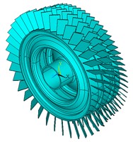
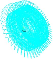
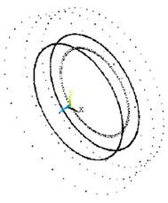
The blade-disk system of an aeroengine compressor is composed of multistage blade disk. The coupling characteristics between different levels of blade disks are considered comprehensively, a three-dimensional solid model of the multistage blade-disk system is established. The structure of the first three stage is shown in Fig. 1, of which the first blade disk is composed of 38 blades and roulette, the second blade disk is composed of 53 blades and roulette, and the third blade disk is composed of 60 blades and roulette. The multistage blade-disk system is divided into substructures using the substructure modal synthesis method. The substructure division of the solid model of the multistage blade-disk system is shown in Fig. 2.
Fig. 1Solid model of multistage bladed-disk system
The material properties of the multistage blade-disk system are shown in Table 1. Each stage blade disk is cut into corresponding blades and roulette disks. Because of the complex structure of multistage blade-disk system, the calculation amount of finite element mesh is very large if the higher-order element is selected. Therefore, solid185 and solid187 are used in this paper to divide the grid of multistage blade-disk system. The meshing of the first, second and third stage blades is dominated by solid185 hexahedral elements, and the rest of the meshing is dominated by solid187 tetrahedral elements. The number of elements and nodes on each level of the blade disk is shown as Table 2. The substructure analysis model of the multistage blade-disk system is shown in Fig. 3.
Fig. 2Substructure solid model of multistage bladed-disk system
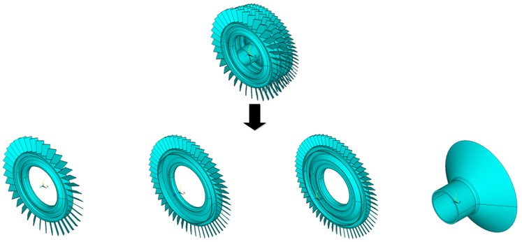
Table 1Material properties of multistage blade-disk system
Material property | Blade property | Roulette property |
Density | 4400 kg/m3 | 8200 kg/m3 |
Elasticity modulus | 1.14 GPa | 1.66 GPa |
Poisson's ratio | 0.3 | 0.3 |
Table 2Number of nodes and elements in a blade-disk system
Number of nodes | Number of units | |
Primary disk | 13225 | 32314 |
Secondary disk | 15276 | 34551 |
Tertiary disk | 37633 | 138876 |
Fig. 3Substructure analysis model of multi-stage blade-disk system
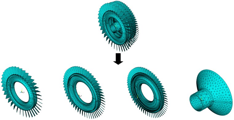
The blade of each stage bladed disk and disk connected with it are divided into one substructure. The first stage blade disk is divided into 38 substructures, the second stage blade disk is divided into 52 substructures, and the third stage blade disk is divided into 60 substructures. The finite element model of the three-stage blade-disk system after the substructure integrated condensed super element is shown in Fig. 4.
Fig. 4Finite element model of multistage blade-disks after condensing super element
a) Super element
b) Node
2.3. Precision verification of substructure reduction model
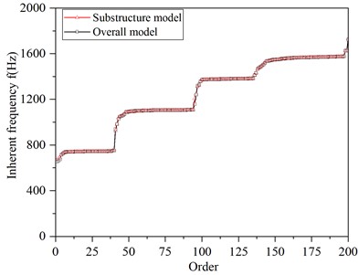
The blade-disk system of the aeroengine compressor is a high-speed rotating power system. Whether the rotational speed is considered in the kinetic analysis will affect the analysis accuracy. Fig. 5 shows the calculation and comparison of natural frequencies of the integral blade-disk model and the substructure model considering the rotational speed.
As can be seen from Fig. 5, the substructure model is in good agreement with the calculation results of the overall blade-disk model within the 200th order, indicating that the substructure model still has a high calculation accuracy of the lower-order modes, and can meet the calculation requirements under the premise of ignoring the higher-order modes, reducing the number of degrees of freedom of the model and improving the calculation speed.
Fig. 5Comparison of dynamic frequency calculation results between the integral blade disk model and the substructure model
In addition, according to the natural frequency distribution of the substructure model, the first 200 modes can be divided into many approximate horizontal regions of “frequency-intensive regions” and the modes of rising regions of corresponding “jump regions”, as shown in Fig. 6.
According to the “frequency-intensive region” in Fig. 6, the comparison and error between the natural frequencies of the “frequency-intensive region” in the 8th to 25th order modes of the integral model and the substructure model were compared, and the following Table 3 was drawn.
In order to verify the accuracy of the calculation results of the substructure model and the overall blade-disk model, the modal shapes of the two models are compared in this paper, as shown in Fig. 7.
It can be seen from the figure that the vibration modes of each order of the substructure model are in good agreement with the analysis results of the overall blade-disk model, and the calculation accuracy of the substructure model is high, which can meet the requirements of the next dynamic calculation.
Fig. 6Division the regions of first 200 order
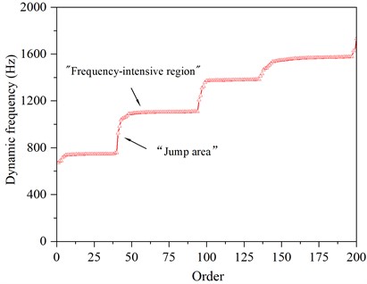
Table 3Comparison of calculation results of inherent frequency
Order | Inherent frequency (Hz) | Relative error (%) | |
Integral model | Substructure model | ||
8 | 739.40 | 739.49 | 0.01 |
9 | 740.03 | 739.82 | –0.03 |
10 | 741.11 | 740.83 | –0.04 |
11 | 741.57 | 741.29 | –0.04 |
12 | 742.01 | 742.03 | 0.00 |
13 | 742.55 | 742.42 | –0.02 |
14 | 742.69 | 742.60 | –0.01 |
15 | 742.92 | 742.80 | –0.02 |
16 | 743.07 | 742.97 | –0.01 |
17 | 743.35 | 743.19 | –0.02 |
18 | 743.43 | 743.48 | 0.01 |
19 | 743.55 | 743.95 | 0.05 |
20 | 743.83 | 744.03 | 0.03 |
21 | 744.32 | 744.14 | –0.02 |
22 | 744.63 | 744.29 | –0.05 |
23 | 744.71 | 744.56 | –0.02 |
24 | 744.92 | 744.62 | –0.04 |
25 | 745.00 | 744.64 | –0.05 |
Fig. 7Comparison of amplitudes between the integral blade disk model and the substructure model
a) Integral model 144th order amplitude of each blade
b) Substructure model 144th order amplitude of each blade
3. Dynamic characteristics analysis of mistuned multistage blade-disk system
3.1. Finite element model of mistuned multistage blade disk
The ideal blade-disk system is cyclic symmetric, but due to processing, installation, wear and other factors, resulting in blade mass, stiffness, natural frequency differences, that is, mistuning [22]. The vibration energy of the blade-disk system will be concentrated in a few blades, which will aggravate the vibration localization degree of the blade-disk system, cause fatigue damage, and adversely affect the life of the compressor blade-disk system. Therefore, it is of great significance to study the mode localization problem caused by the parameter mistuning of the blade-disk system.
3.2. Model description
The finite element model of the mistuned multistage blade-disk system is established. Only the parameters of blade and disk are different from those of the harmonic multistage blade-disk system, such as the mass parameter and the stiffness parameter.
The mass mistuning and the stiffness mistuning of the blade-disk system are respectively considered. The mass mistuning is and the stiffness mistuning is . The expressions of the stiffness and mass of the blade-disk system are shown in Eq. (20) and Eq. (21):
where: – the stiffness value of the mistuned multistage blade-disk system, – the mass value of the mistuned multistage blade-disk system, – the stiffness value of the harmonic multistage blade-disk system, – the mass value of the harmonic multistage blade-disk system.
Random mistuning of the mass and the stiffness is realized by Monte Carlo sampling method. Six groups of sampling samples are set, and data are extracted in groups. The sampled data are uniformly distributed with mean value of 0 and standard deviation of 1 %, 2 % and 5 %, respectively, as shown in Table 4.
Table 4Sampling of mistuning mass
Parameters | Mistuning condition | Mean value | Sample size |
1 % | 0 | 10000 | |
2 % | 0 | 10000 | |
5 % | 0 | 10000 | |
1 % | 0 | 10000 | |
2 % | 0 | 10000 | |
5 % | 0 | 10000 |
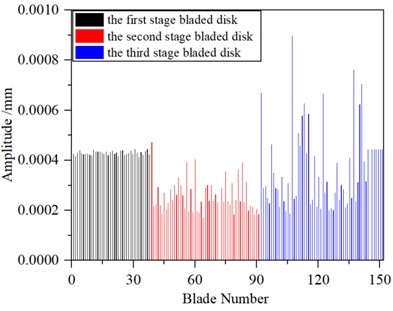
The first set of sampling results (defined as mistuning1) is shown in Fig. 8.
The sampling of mistuning1 is uniformly distributed. The mistuning mass of the primary disk is numbered 1-38, the mistuning mass of the secondary disk is numbered 39-91, and the mistuning mass of the tertiary disk is numbered 92-151.
3.3. Response localization characteristics of mistuned multistage blade-disk system
The forced vibration of the disk is induced by the excitation force of the mistuned disk and determines the mode shape of the system. The multistage blade-disk system will vibrate continuously for a long time under the influence of a certain excitation, which will cause high cycle fatigue failure, crack and even fracture.
The expression of the exciting force on the -th blade is shown in the following Eq. (22):
where: – excitation force amplitude, – excitation frequency, – phase angle.
The excitation force is applied as shown in Fig. 9.
Fig. 8Results of the first sample
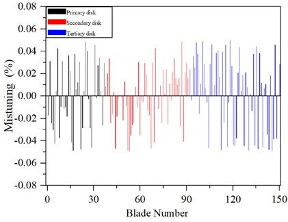
Fig. 9The value of the excited force of a multistage blade-disk system
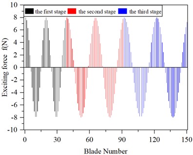
a) Real part exciting force
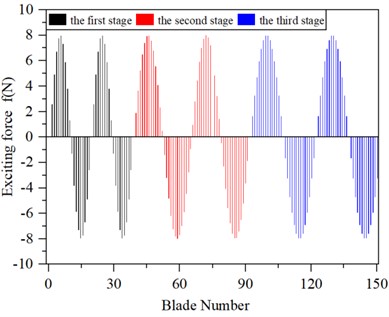
b) Virtual part exciting force
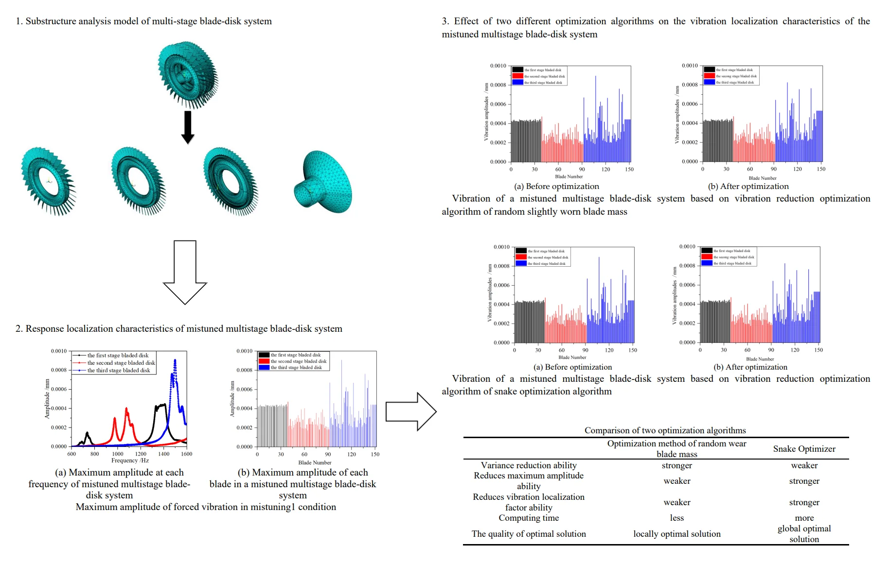
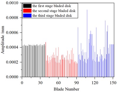
The harmonic response of the mistuned multistage blade-disk system (mistuning1) is analyzed, and the sweep frequency segment is defined as 600-1600 Hz. The vibration amplitude of the mistuned multistage blade-disk system at each frequency is shown in Fig. 10.
As shown in Fig. 10(a) and Fig. 10(b), the black, red and blue lines in the figure correspond to the first, second and third-order blades of the disk system respectively. The vibration amplitudes of third-order blades corresponding to different frequencies can be obtained from Fig. 10(a), and the blades with the highest amplitudes of the third-order blades can be obtained from Fig. 10(b). The resonance frequency of the mistuned multistage blade-disk system occurs around 740 Hz, 970 Hz, 1050 Hz, 1320 Hz, 1400 Hz and 1500 Hz, and the maximum resonance peak value is 9.09×10⁻⁴ mm.
4. Vibration reduction optimization analysis of mistuned multistage blade-disk system
The natural frequency of blade vibration is closely related to the stiffness and the mass of the blade. According to Eq. (23) and Eq. (24), it can be concluded that by changing the stiffness or the mass of the blade, the optimization of vibration reduction for a mistuned multistage blade-disk system can be achieved. Changing the stiffness of the blades can be achieved by introducing a disturbance coefficient , i.e.:
where, is the stiffness value of the -th mistuned blades, is the stiffness value of the harmonic blade, is the disturbance coefficient, is the number of the blade, is the number of blades in each stage of the blade disk.
Changing the quality of the blades can be achieved by introducing a disturbance coefficient , i.e.:
where, is the mass value of the -th mistuned blades, is the mass value of the harmonic blade, is the disturbance coefficient, is the number of the blade, is the number of blades in each stage of the bladed disk.
Fig. 10Maximum amplitude of forced vibration in mistuning1 condition
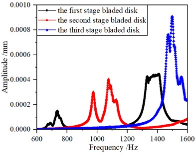
a) Maximum amplitude at each frequency of mistuned multistage blade-disk system
b) Maximum amplitude of each blade in a mistuned multistage blade-disk system
Fig. 11Maximum amplitude of forced vibration in mistuning2 condition
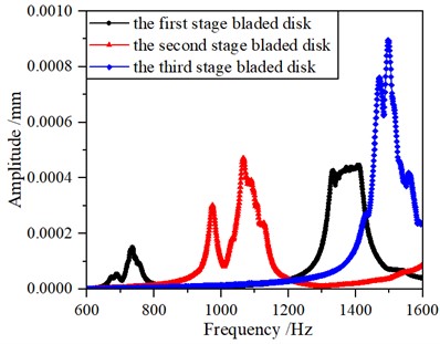
a) Maximum amplitude at each frequency of a mistuned multistage blade-disk system
b) Maximum amplitude of each blade in a mistuned multistage blade-disk system
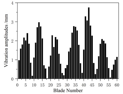
In order to explore whether the change of the blade mass affects the vibration of the system, a blade mass is randomly slightly worn (the mistuning amount is controlled within 6 %) in the above mistuning1 working condition, and the maximum amplitude of forced vibration of the system in mistuning2 working condition is obtained under the same exciting force vector, as shown in Fig. 10. Fig. 11(a) shows the maximum amplitude of each blade in the whole frequency band when the excitation frequency changes from 600 Hz to 1600 Hz. Fig. 11(b) shows the maximum amplitude of each blade of the primary, secondary and tertiary disk when the excitation frequency changes from 600 Hz to 1600 Hz. In this frequency band, the maximum amplitude of each blade occurs on the third-stage blade disk, and the maximum value is 8.96×10⁻⁴ mm, and the average value of the maximum amplitude of each blade on the third-stage blade disk is 3.69×10⁻⁴ mm.
According to the above analysis, it can be seen that the maximum response amplitude of the blade-disk system decreases from 9.09×10⁻⁴ mm to 8.96×10⁻⁴ mm after the system changes from mistuning1 condition to mistuning2 condition through random wear of the blade mass (in mistuning1 condition). It is found that the maximum amplitude of the forced vibration of the mistuned multistage blade-disk system can be reduced by slightly worn the blade mass. The above slightly worn the blade mass test can be repeated many times, and similar results can be obtained. Therefore, it is considered that the maximum amplitude of the multistage blade-disk system can be reduced by slightly wearing the mass of several blades.
4.1. Vibration reduction optimization algorithm of random slightly worn blade mass
The model of the multistage blade-disk system consists of three stage blade-disks with 151 blades. The parameters of each blade are defined. The finite element reduction model of the mistuned multistage blade-disk system is established by using the substructure modal synthesis method, and the analysis files of four substructures are generated. The dynamic analysis of the multistage blade-disk system generated by each substructure analysis file set is carried out.
Fig. 12Flow chart of vibration reduction optimization algorithm for random slightly worn blade mass
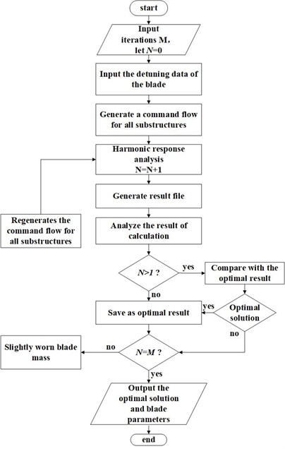
It can be seen from literature [24] that the maximum amplitude of a blade-disk system is not only related to its own mistuning, but also to the frequency of adjacent blades. In the analytical model presented in this paper, adjacent blades can be blades of the same level of disks or blades of adjacent stages. According to the above conclusions, if the parameters of blades adjacent to the maximum amplitude are fine-tuned, that is, the amplitude of the blade-disk system will inevitably change after the mass of other blades is slightly worn. Based on the above ideas, the results of each iteration calculation are saved, and the mass of the blade is continuously fine-tuned at random (and the mistuning of blade parameters is controlled within 6 %), while the parameters of other blades remain unchanged, which can optimize the multistage blade-disk system faster. In this paper, the independent operation of the optimization algorithm is realized by writing MATLAB program and ANSYS command flow. The flow chart of the optimization algorithm of the multistage blade-disk system is shown in Fig. 12.
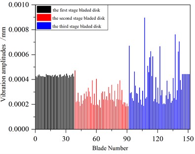
In order to facilitate the comparison, the mistuning1 condition is optimized by using the optimization algorithm of random slightly worn the blade mass in this paper, and the maximum amplitude of each blade in the whole frequency band when the excitation frequency changed from 600 Hz to 1600 Hz before and after optimization is calculated. The optimization results are verified, and it is found that the vibration of the blade-disk system could be greatly improved by slightly worn the blade mass. The maximum amplitude of each blade before and after optimization is shown in Fig. 13.
Fig. 13Vibration of a mistuned multistage blade-disk system
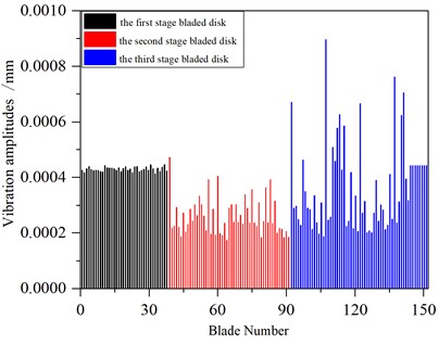
a) Before optimization
b) After optimization
The maximum amplitude of the system before and after optimization appeared on the third stage blade disk, and the maximum amplitude before optimization is 9.09×10⁻⁴ mm, and the maximum amplitude after optimization is 8.57×10⁻⁴ mm.
The maximum amplitude, variance and localization factor of the blade are usually used as evaluation indexes to evaluate the quality of the vibration of the mistuned multistage blade-disk system. The vibration localization factor proposed in literature [25] is adopted to consider the proportional relationship between the vibration energy of the blade and the square of its deformation. In order to facilitate calculation, the displacement change of the blade tip is used to represent the vibration of the blade. The maximum amplitude in the blade-disk structure and the amplitude of other blades are used to describe the degree of modal localization of the blade-disk system. The modal localization parameters are shown in the following Eq. (25):
where: – the number of blades, – the serial number of the blade with the largest amplitude, – the largest amplitude.
In this paper, the Eq. (25) is used to evaluate the optimization results. The equation was proposed by Wang Hongjian [25] of Northwestern Polytechnical University, and the author has verified in the paper that the evaluation method is accurate and effective.
It is known that the maximum amplitude of the mistuned multistage blade-disk system is located on the third-stage blade disk. The comparison of variances, maximum amplitudes and vibration localization factors of each blade before and after the third-stage blade disk optimization is shown in Table 5.
Table 5Comparison of vibration before and after optimization
Before optimization | After optimization | Optimization range (%) | |
Variance | 2.57×10⁻⁸ | 2.52×10⁻⁸ | 1.95 |
Maximum vibration amplitude | 9.09×10⁻⁴ | 8.57×10⁻⁴ | 5.72 |
Vibration localization factor | 2.10 | 1.85 | 12.0 |
According to the analysis in Table 5, the variance, maximum vibration amplitude and vibration localization factor after optimization decreased by 1.95 %, 5.72 % and 12.0 % respectively. The degree of vibration localization of the mistuned multistage blade-disk system is obviously reduced, which verifies the correctness of the optimization algorithm in this paper.
In order to evaluate the effectiveness of the algorithm on the control of vibration localization of the mistuned blade-disk system, this article adopted the calculation equation of localization factor in the ref. [26] and verification the algorithm. Please refer to Eq. (26) for the vibration localization factor in detail:
where, – maximum amplitude vector of each blade, is the mean of maximum amplitude of each blade, is the maximum amplitude variance of each blade.
Table 6Vibration localization factor L' of blades before and after optimization
Before optimization | After optimization | Optimization range (%) | |
Vibration localization factor | 7.71×10⁻¹² | 7.308×10⁻¹² | 5.21 |
The localization factor before and after optimization is calculated by the Eq. (26) and contrast as shown in Table 6. As shown from Table 6, the localization factor after optimization is reduced greatly by adopting the Eq. (26), the correctness of the optimization algorithm presented in this paper is verified.
4.2. Vibration reduction optimization algorithm based on snake optimization algorithm
The Snake Optimizer (SO) is inspired by the mating behavior of snakes. In 2022, a new meta-heuristic algorithm is proposed for the first time in literature [27], which is a new intelligent optimization algorithm that mimics the mating behavior of snakes. In this section, the snake optimization algorithm is introduced to analyze and optimize the vibration response characteristics of the mistuned multistage blade-disk system.
The snake optimization algorithm, like all meta-heuristics, starts with generating a uniformly distributed random population so that the process of optimizing the algorithm can begin. For the convenience of comparison, the initial population here is still studied with mistuning1. Two groups of populations are defined, male and female, and it is assumed that the leaves of the blade disk where the maximum amplitude is located are defined as male, and the leaves of the remaining blade disks are defined as female. The male and female expressions are shown in Eq. (27):
where: – total number of individuals, – number of males, – number of females.
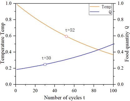
After defining the temperature and amount of food, and identifying the best individuals in each group (i.e. the situation where the current stage reduces the amplitude of the blades most), the best males () and the best females () and the location of food () are got. The Temp expression is shown by the following Eq. (28):
where represents the current number of iterations, represents the maximum number of iterations. Define the quantity of food () as expressed in the following Eq. (29):
where: is constant and equals 0.5.
If < threshold (threshold = 0.25), the snake searches for food by selecting any random location and updating their position relative to the food (i.e. random slight wear of blade mass). To model the exploration phase, the mass change expression of the -th blade is shown in Eq. (30):
where: – the position of the -th male, – the position of the -th female, – random number, between the interval [0, 1], – the male’s ability to find food, – the female's ability to find food, – the fitness of the -th male individual, taking the maximum amplitude of the blade as the index, the lower the maximum amplitude, the higher the fitness, – the fitness of -th female individual, – fitness of random male individual, – fitness of random female individual, is constant and equals 0.05.
Development phase (find the situation to reduce blade amplitude):
If > threshold, and if Temp > 0.6, the snake will move to the food (record the current optimization parameters).
If > threshold, if Temp < 0.6, the snake will initiate the battle mode, then the optimal male/female individual is obtained and the mating pattern shown in Eq. (31) below is performed:
where: – male mating ability, , – female mating ability, , is constant and equals 2.
If the egg hatches, the worst male and female individuals are replaced by Eq. (32):
The algorithm flow is shown in Fig. 14, and the relationship between cycle times , temperature Temp and food quantity is shown in Fig. 15.
Fig. 14Flow chart of snake optimization algorithm
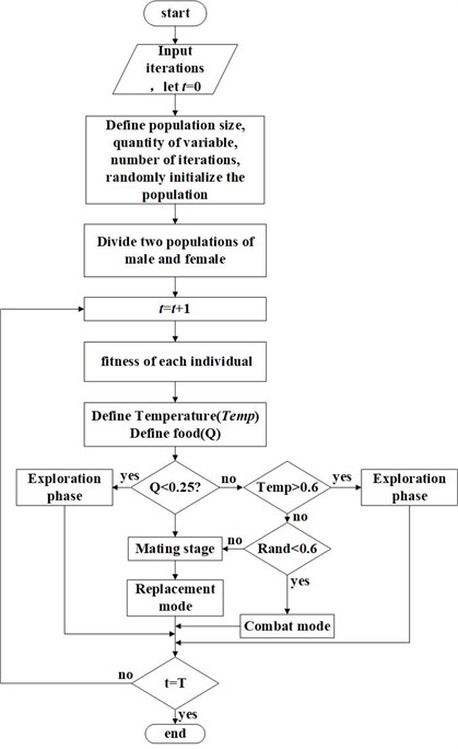
Fig. 15Graph of the number of cycles, temperature, and quantity of food
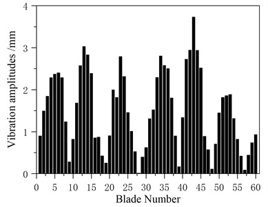
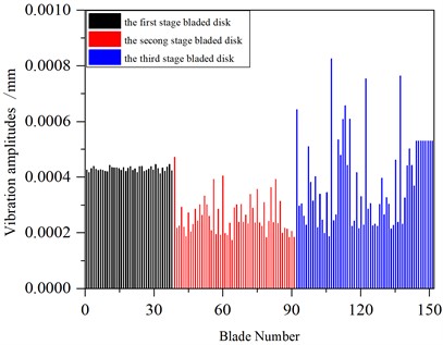
In order to facilitate comparison, the snake optimization algorithm is adopted to optimize the mistuning1 condition in Section 3.1, and the maximum amplitude of each blade in the whole frequency band when the excitation frequency changed from 600 Hz to 1600 Hz before and after optimization is obtained. The optimization results are verified, and it is found that the vibration response of the blade-disk system could be greatly improved by slightly wearing the blade mass. The maximum amplitude of each blade before and after optimization is shown in Fig. 16.
Fig. 16Vibration of a mistuned multistage blade-disk system
a) Before optimization
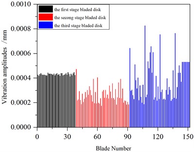
b) After optimization
The maximum amplitude of the system before and after optimization appeared on the third stage blade disk, and the maximum amplitude before optimization is 9.09×10⁻⁴ mm, and the maximum amplitude after optimization is 8.26×10⁻⁴ mm.
The maximum amplitude, variance and vibration localization factor of blades in 3.1 are also used as evaluation indexes to evaluate the quality of vibration of the system. It is known that the maximum amplitude of the mistuned multistage blade-disk system is located on the third-stage blade disk, and the comparison of variances, maximum amplitudes and vibration localization factors of each blade before and after the third-stage blade disk optimization is shown in Table 7.
According to the analysis in Table 7, the variance, maximum vibration amplitude and vibration localization factor after optimization are reduced by 0.78 %, 9.13 % and 16.7 % respectively. The degree of vibration localization of the mistuned multistage blade-disk system is significantly reduced, which verifies the correctness of the optimization algorithm in this paper.
Table 7Comparison of vibration before and after optimization
Before optimization | After optimization | Optimization range (%) | |
Variance | 2.57×10⁻⁸ | 2.55×10⁻⁸ | 0.78 |
Maximum vibration amplitude | 9.09×10⁻⁴ | 8.26×10⁻⁴ | 9.13 |
Vibration localization factor | 2.10 | 1.75 | 16.7 |
4.3. Comparison of results of two optimization algorithms
The vibration reduction optimization results of random wear the blade mass are compared with those based on snake optimization algorithm, as shown in Table 8.
Table 8Comparison of two optimization algorithms
Optimization method of random wear blade mass | Snake optimizer | |
Variance reduction ability | Stronger | Weaker |
Reduces maximum amplitude ability | Weaker | Stronger |
Reduces vibration localization factor ability | Weaker | Stronger |
Computing time | Less | More |
The quality of optimal solution | Locally optimal solution | Global optimal solution |
The comparison results show that the two optimization algorithms have their own advantages. The first algorithm can quickly reduce the amplitude of the blade, but its ability to reduce the amplitude and vibration localization factor is weak, and it is easy to fall into the local optimal solution. The second algorithm costs more computer time, but its ability to reduce amplitude and vibration localization factor is strong, and the global optimal solution can be found when the number of iterations is sufficient.
5. Conclusions
In this paper, the mistuned multistage blade-disk system of aeroengine compressor is studied. Based on the substructure modal synthesis method, the finite element reduction model of the blade-disk system is established, and the vibration reduction optimization algorithm is established. Optimization research on the vibration reduction in the condition of the blade mass mistuning is carried out, and the following conclusions are obtained:
1) Based on the substructure modal synthesis method, the overall structure of the blade-disk system is divided into four substructures considering the inter-stage coupling, which not only considers the inter-stage coupling of the multistage blade-disk system, but also improves the calculation speed and efficiency. In the first 200 modes, the natural frequencies of the substructure model and the overall blade-disk model have a high agreement.
2) Aiming at the problem of the mass mistuning optimization of blades, the vibration reduction optimization method using random slight wear of a blade mass (the mistuning is controlled within 6 %) can reduce the degree of vibration localization based on the finite element reduction model. Each optimization calculation only regenerates the substructure with the change of the mass, which saves a lot of computer time under the premise of ensuring the calculation accuracy, and the calculation efficiency is high. Based on the snake optimization algorithm, an optimization model of the mistuned multistage blade-disk system is established. The blade disk with the maximum amplitude is defined as the male population, and the remaining sub-structures are defined as the female population. The optimal solution of the two populations is selected for mating, and the next generation is obtained. By comparing the vibration reduction optimization solutions, the optimal solution can be obtained through a certain number of iterations, that is, a small amount of the blade mass is worn (the mistuning is controlled within 6 %), and the maximum amplitude of the mistuning multistage blade-disk system is reduced.
3) The research shows that the optimization method used in this paper can effectively reduce the degree of vibration localization of the mistuned blade-disk system, and the global optimal solution can be found when the number of iterations is sufficient. The two optimization algorithms proposed in this paper can both reduce the degree of vibration localization and increase the life of aeroengine. The analysis method presented in this paper takes into account the analysis efficiency and analysis precision, and can provide a theoretical basis for the optimization of vibration reduction in practical engineering.
References
-
H. Zhang, H. Yuan, and W. Yang, “Optimization of vibration reduction of mistuned blades based on pre-stressed component mode synthesis method,” (in Chinese), Journal of South China University of Technology (Social Science Edition), Vol. 46, No. 2, pp. 73–80, 2018.
-
S. Wang, L. Sun, and J. Wu, “A dynamic vibration absorber array method for multi-mode vibration mitigation of mistuned integrally bladed disk,” (in Chinese), Chinese Journal of Theoretical and Applied Mechanics, pp. 1–11, Oct. 2023.
-
X. Yu and S. Lu, “Integrative design method of blisk considering structure strength and resonant vibration avoidance,” (in Chinese), Journal of Aerospace Power, Vol. 28, No. 10, pp. 2235–2239, 2013.
-
S. Lu and F. Lu, “Structure optimization design for blisk based on ANSYS,” (in Chinese), Journal of Aerospace Power, Vol. 27, No. 6, pp. 1218–1224, 2012.
-
S. Lu and L. Li, “Twin-web structure optimization design for heavy duty turbine disk based for aero-engine,” (in Chinese), Journal of Propulsion Technology, Vol. 32, No. 5, pp. 631–636, 2011.
-
F. Gao, X. Liu, and B. Yu, “Multi-objective optimization design for vibration parameters of nonlinear hard-coating blisk,” (in Chinese), Journal of Aerospace Power, Vol. 37, No. 1, pp. 103–113, 2022.
-
Z. Fan, M. Ma, and R. Wang, “Optimal design of space engine integral blade disk,” (in Chinese), Gas Turbine Experiment and Re-Search, No. 4, pp. 27–30, 2000.
-
Y. Dai, C. Jiang, and S. Lu, “Development and application of blades installation arrangement order optimizing system based on genetic algorithm,” (in Chinese), Turbine Technology, Vol. 45, No. 5, pp. 270–272, 2003.
-
T. Liu, L. Zhang, and X. Li, “Effect of ant colony algorithm and improved particle swarm algorithm on the layout of blade vibration reduction,” (in Chinese), Journal of Liaoning University of Technology, Vol. 35, No. 6, pp. 388–391, 2015.
-
L. Zhang, T. Liu, and X. Li, “Research overview on vibration damping of mistuned bladed disk assemblies,” (in Chinese), Journal of Hebei University of Science and Technology, Vol. 37, No. 2, pp. 109–117, 2016.
-
H. Jing, “Reliability analysis and optimization design of mistuning blisk vibration,” (in Chinese), Harbin University of Science and Technology, 2019.
-
T. Zhao, “Research on dynamic characteristics and optimization method of blade-disk system of the aircraft engine,” (in Chinese), Northeastern University, 2019.
-
W. Choi and R. H. Storer, “Heuristic algorithms for a turbine-blade-balancing problem,” Computers and Operations Research, Vol. 31, No. 8, pp. 1245–1258, Jul. 2004, https://doi.org/10.1016/s0305-0548(03)00078-9
-
H. Zhang, H. Yuan, and H. Sun, “Vibration reduction optimization for mistuned bladed disk based on reduced order modeling technique,” Journal of Vibroengineering, Vol. 23, No. 2, pp. 385–399, Mar. 2021, https://doi.org/10.21595/jve.2020.21381
-
E. Thompson and G. Becus, “Optimization of blade arrangement in a randomly mistuned cascade using simulated annealing,” in 29th Joint Propulsion Conference and Exhibit, Jun. 1993, https://doi.org/10.2514/6.1993-2254
-
P. Bisegna and G. Caruso, “Optimization of a passive vibration control scheme acting on a bladed rotor using an homogenized model,” Structural and Multidisciplinary Optimization, Vol. 39, No. 6, pp. 625–636, Apr. 2009, https://doi.org/10.1007/s00158-009-0375-3
-
L. Lin, D. Pengcheng, and L. Chao, “Research on vibration suppression of bladed disk structure with bi-periodic piezoelectric networks,” Journal of Propulsion Technology, Vol. 37, No. 1, pp. 156–165, 2016.
-
L. Lin, L. Jiuzhou, and L. Chao, “Analysis on vibration suppression of mistuned bladed disk viabi periodic distributed piezoelectric shunt damping,” (in Chinese), Journal of Aerospace Power, Vol. 32, No. 3, pp. 666–676, 2017.
-
W. Wuguo and P. Weicheng, “Optimization analysis of compressor blade-disc structure from an engine,” (in Chinese), Science Technology and Engineering, Vol. 22, No. 34, 2022.
-
X. You, H. Feng, H. Zhang, and J. Wang, “Analysis of random mistuning vibration characteristics of multi-stage bladed disk system,” in 9th International Conference on Mechanical Engineering, Materials, and Automation Technology (MMEAT 2023), Oct. 2023, https://doi.org/10.1117/12.3007321
-
T. Bian, “Study on vibration response of blade mass detuning to the whole blade disk,” (in Chinese), Shenyang University of Chemical Technology, 2023.
-
Z. Yang, T. Bian, and P. Dang, “Vibration response characteristics of integral blade disc under blade mass detuning,” (in Chinese), Journal of Mechanical and Electrical Engineering, Vol. 39, No. 8, pp. 1138–1144, 2022.
-
X. Liang, J. Wang, and H. Pan, “Study on vibration localization characteristics of detuned blad-disk system,” (in Chinese), Turbine Technology, Vol. 65, No. 1, pp. 43–45, 2023.
-
H. Zhang et al., “Vibration reduction optimization of the mistuned bladed disk considering the pre-stress,” Proceedings of the Institution of Mechanical Engineers Part G Journal of Aerospace Engineering, pp. 226–239, 2019.
-
H. Wang, E. He, and Z. Zhao, “Investigating further resonant response characteristics of disk with randomiy mistuned blades,” (in Chinese), Journal of Northwestern Polytechnical University, Vol. 29, No. 2, pp. 189–193, 2011.
-
H. Q. Yuan, L. Zhang, and Q. K. Han, “Optimization of mistuning blades arrangement for vibration absorption in an aero-engine based on artificial ant colony algorithm,” (in Chinese), Journal of Vibration and Shock, Vol. 31, pp. 169–172, 2012.
-
F. A. Hashim and A. G. Hussien, “Snake optimizer: a novel meta-heuristic optimization algorithm,” Knowledge-Based Systems, Vol. 242, p. 108320, Apr. 2022, https://doi.org/10.1016/j.knosys.2022.108320
About this article

This research was funded by the research foundation of the Education Department of Liaoning Province (JYTMS20230213).
The datasets generated during and/or analyzed during the current study are available from the corresponding author on reasonable request.
Xiaomei You: conceptualization, methodology, writing-original draft preparation. Haiyu Feng: software, validation, data curation, writing-original draft preparation. Hongyuan Zhang: formal analysis. Pengbo Liu: writing-review and editing.
The authors declare that they have no conflict of interest.
