Abstract
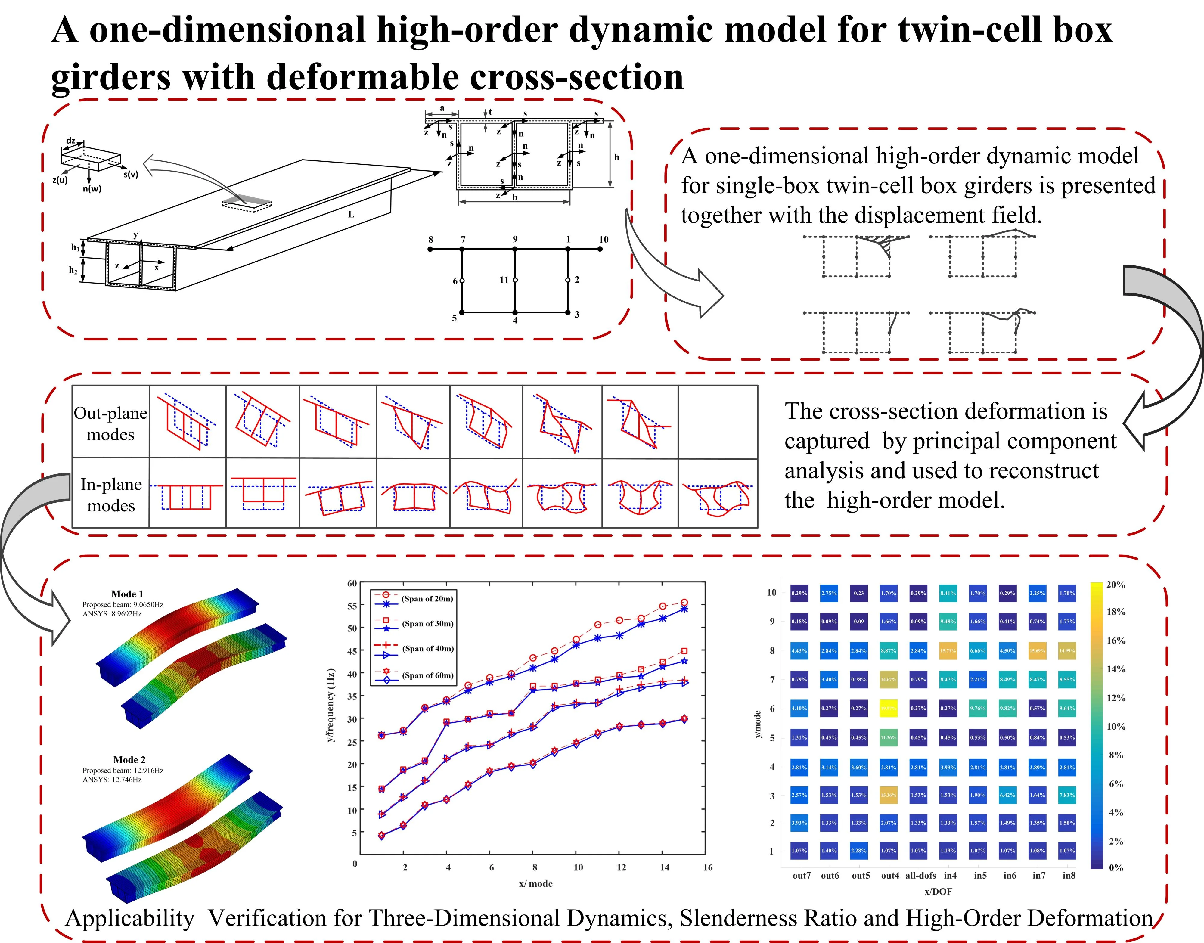
A one-dimensional high-order dynamic model for single-box twin-cell box girders is presented together with the pattern recognition algorithm. The model takes into account the deformable cross-section and can accurately predict its 3D dynamic behaviors. The cross-section deformation is captured by basis functions satisfying displacement continuity condition, which is essential to construct the initial model formulation based on the Hamilton principle. The axial variation patterns of generalized coordinates are decoupled by solving the eigenvalue problem. On this basis, the combinations of basis functions are obtained to bring out cross-section deformation. The cross-section deformation, hierarchically organized and physically meaningful, are used to update the basis functions in the reconstructed high-order model. Numerical analysis has verified the accuracy and applicability of the reconstructed one-dimensional high-order model.
Highlights
- A one-dimensional high-order dynamic model for single-box twin-cell box girders is presented together with the pattern recognition algorithm. A set of shape functions is defined to capture cross-sectional deformation to construct the one-dimensional high-order initial model.
- The cross-section deformation is captured by principal component analysis and used to reconstruct high-order model in order to reduce the degree of freedom of the model and improve computational efficiency.
- The reconstructed high-order model, which is compared with the ANSYS model, is validated for the applicability of three-dimensional dynamics, slenderness ratio and high-order deformation.
1. Introduction
With the continuous development of transportation and engineering technology, bridge structures have become widely used in highways. Box girders play an important role in the load-bearing capacity of bridge structures, due to their excellent seismic resistance, bending and torsion resistance, and overall load-bearing performance. As research progressed the fabrication of the box girders have undergone several variations from the initial use of cast-in-place brackets to later prefabricated installations. There have also been some changes in the cross-section configuration of box girders, such as the number of box chambers and the form of composite box sections. The traditional single-box single-cell section structure [1]-[3] is lightweight and has strong applicability, but the single-box twin-cell box girder bridge gradually appears in the public's view with the rapid increase of traffic flow [4]-[5]. The stress characteristics of the box girder are completely different from those of the single-box single-cell box girder. At the same time, the rapidly growing traffic demands emphasize the need for box girder bridges with more and more lanes. The single-box single-cell box girder bridge cannot meet the requirement. Therefore, it is inevitable to research and develop twin-cell box girder bridges.
Box girders generally have a large span and a cross-section constructed with thin walls, belonging to typical thin-walled structures. The theories of thin-walled structures have been developing constantly, which can provide supports for the mechanical analysis of box girders. Usually, various external forces borne by the box girder section are divided into symmetrical dead loads and symmetrical or asymmetric live loads. The box girder will deform for bending and torsion under these loads. To rationally evaluate its performance, researchers have made quantities of efforts. The measures adopted are generally divided into model experiment method and analytical method. The former method usually reduces the box girder to a certain proportion to study its characteristics. For example, Chithra et al. [6] studied the formation process of cracks on the surface of the twin-cell box girder bridge under the combined action of bending and torsion, and Androus et al. [7] investigated free vibration and ultimate behavior of composite twin-box girder bridges to study the effect of internal cross bracing between box girders along with the curvature effect at different loading stages.
Analytical methods have played important role in explaining special behaviors of box girders. Typically, some researchers have considered the effect of initial curvature to obtain analytical expressions which describes the bending-torsion coupling characteristics of curved box girders under different loads. They provide a theoretical basis for the application under special terrain conditions [2]-[4]. Taking the shear of box girder into account, Zhu et al. [8] developed a modeling strategy to describe the distortion of composite trapezoidal box girders with cantilever overhangs while considering various indices and shear deformation of inner cross-frames. Zhang et al. [9] provided a solution to improve the buckling and shear performance for the bionic box girder bridge with steel webs. At the same time, the phenomenon of shear lag in the wing plates of wide flange box girders has a notable impact on structural performance of box girders. Some scholars have revealed the distribution of shear flow in box girders [10]-[12].
The stress state of box girder bridges under various loads during construction and operation stages is more complex. In addition to bending and torsional deformation, spatial effects such as distortion and local lateral bending are prominent. Classical beam theory, such as Euler beam [13], is a simplified form of linear elastic theory for beams and is widely used for load-bearing and deformation calculations. However, it ignores the effects of section warping and distortion. Currently, in order to accurately characterize its 3D structural behavior, the high-order beam theory [14] has been further developed by considering cross-sectional characteristic deformation. On the basis of traditional beam theory, the deformation mode of special behavior is considered to enhance the capability to predict cross-section deformations. Vlasov theory [15]-[16] is among the earliest ones in analyzing high-order beams. It defines cross-sectional warping and includes cross-sectional deformation shapes as additional degrees of freedom.
Later, the concept of generalized warping function was further used by many authors. For example, R. Vieira [14] provided a procedure to define uncoupled warping modes within the framework of a higher-order beam model. Choi et al. [16] proposed a higher-order beam bending theory, which not only includes as many bending related section modes as possible, but also provides the required explicit relationship between stress and generalized forces. To evaluate the vibration of thin-walled beams with arbitrary open sections, Jrad et al. [17] derived an analytical expression for the beam in bending-torsion coupled modes. Kim et al. [18] derived the cross-sectional shape functions of high-order deformation modes, which are used to analyze thin-walled beams composed of straight section edges. Zhou et al. [19] put forward the analytical deflection theory considering the strain and displacement of each plate in a single-cell box girder. The shear deformation of box girder web and flange is considered under continuous deformation condition. Vieira et al. [20] proposed a procedure to calculate cross-section deformation modes of steel-concrete composite bridge. Henriques et al. [21] presented and validated a finite element that combines the effects of concrete creep and cross-section deformation, namely distortion and shear lag. Barrientos et al. [22] proposed a one-dimensional element for thin-walled beams considering torsion, deformation and shear hysteresis.
In this paper, a one-dimensional high-order dynamic model is presented which considers the cross-sectional deformation of a single-box twin-cell box girder. First, a set of basic deformation modes of the cross-section is defined, and shape functions are used to capture the displacement of the cross-section. The initial one-dimensional high-order dynamic model is presented in Section 2. The principal component analysis method is employed to efficiently extract cross-sectional feature deformation patterns with certain physical significance, and the dynamic model is further updated using feature deformations in Section 3. In the identification procedure, geometric and boundary conditions are also considered. In Section 4, the universality and effectiveness of the updated one-dimensional high-order dynamic model are verified through comparison with shell model. Finally, the main conclusions are outlined.
2. One-dimensional high-order beam model
2.1. Displacement field
The research object of this paper is the twin-cell box girder with equal cross-section shown in Fig. 1(a). The parameters L, h, b, a, and t respectively represent the overall length, web height, bottom plate width, wing plate length and wall thickness of the box girder. To describe the displacement field, a global coordinate system (x,y,z) is set with its origin located in the centroid of the cross-section at one end of the box grider. The z-axis is parallel to the beam axis, while the x-axis and y-axis represent the tangential and normal directions of the cross-section, respectively. Thin-walled sections are discretized along the centerline, and the local coordinate system (s,n,z) is adopted on the wing plate and web of the twin-cell box girder in Fig. 1(b), where the s-axis and n-axis define the centerline plane of the plate, and z-axis represents the direction along the axis.
Fig. 1The single-box twin-cell girder: a) the global coordinate system, b) the local coordinate system, and c) discretization nodes of the cross-section
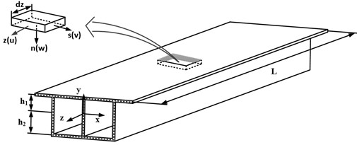
a)
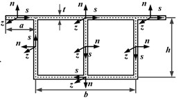
b)
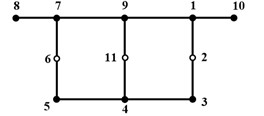
c)
The displacement field is built to accurately describe the cross-section deformation in the means of combinations of a set of shape functions defined on the cross-section. These shape functions are one-dimensional and satisfy displacement continuity conditions along the centerline.
As shown in Fig. 1(c), the twin-cell box girder cross-section can be divided into a set of walls, connected by eight natural nodes, which connects adjacent walls or locates at the free ends. Since three webs may be relatively large in length, appropriate node refinement will contribute to the capability of capturing cross-section deformation from the view-point of interpolation [23]. Besides, three artificial nodes are addtionally employed to discretize the centerline in Fig. 1(c). Unit displacements are applied to each node along the axial, tangential, normal, and rotation direction, as shown in Fig. 2. The adjacent nodes are constrained to have zero displacement. As a result, the discrete nodes on the twin-cell box girder generated four basic deformation modes, including one out-of-plane deformation mode and three in-plane deformation modes. Therefore, a total of forty-four basis functions are defined on the discrete cross-section, enabling a clear expression of forty-four basic deformations.
According to one-dimensional high-order theory, the displacement field h of the box girder section is described by three components, namely u(s,z), v(s,z), and w(s,z), respectively. They are approximated by a set of basis functions about s, which are formulated by the displacement interpolation between cross-section nodes. The displacement field h are specifically represented as:
where ai(s) is the basis function vector using one time Lagrange interpolation, representing the axial deformation outside the section.ψi(s) and βi(s) are the basis function vectors of tangent s and normal n deformation in the plane, respectively, which are obtained by Lagrange and Hermite interpolation functions:
Fig. 2Basic deformation modes of the twin-cell box girder cross-section with eleven discrete nodes
The discrete nodes on the centerline of the cross-section of the twin-cell box girder generate forty-four basic deformations. They can accurately express the displacement changes of the twin-cell box girder section. γ(z) is introduced to represent the weight matrix corresponding to the forty-four basis functions, and can be expressed as:
According to Kirchhoff’s thin-plate assumption, the displacement field H of the twin-cell box girder is represented by three components, namely U(s,n,z), V(s,n,z) and W(s,n,z) for the axial, tangential and normal components, respectively:
Based on the basic assumption of Saint Venant Kirchhoff elastic body, each box girder element exhibits linear, elastic, and isotropic behavior. The strain vector ε of the twin-cell box girder is obtained as:
where C2 is a differential operator. According to the linear elastic Constitutive equation, the stress vector σ of the twin-cell box girder is derived from the generalized Hooke’s law:
where, R is the constitutive matrix, E describes the elastic modulus, G denotes the shear elastic modulus, and v represents the Poisson’s ratio of material.
2.2. Governing equations
The governing equation of the twin-cell box girder is derived by using the Hamiltonian principle. It reads:
where, t1 and t2 are boundary time, T, U, and W are the kinetic energy, strain energy of the twin-cell box girder and the external force work acting on the twin-cell box girder. Each component can be expressed as:
where ρ is the material density, F is the column vectors of distributed forces acting on the cross-section [2, 25], V and A are the volume and cross-sectional area of the twin-cell box girder. By substituting Eqs. (8-10) into Eq. (7), the dynamics equation of the box grider can be derived as follows:
For ease of calculation, the finite element method is used to discretize the box grider into m elements along the axial direction:
where N is the interpolation function in the axial direction and di is the generalized displacement vector. The vector N and di are expressed as follows:
where ζ1 and ζ2 are linear interpolation functions and the subscripts (i) and (i+1) indicate the ends of an element.
The single-box twin-cell box girder in this paper is in a free vibration state without damping, so the load vector F is treated as zero. Substituting Eqs. (12-14) into Eq. (11) leads to the following equation:
The form of the dynamics equation Eq. (15) can be rearranged as:
where m is element mass matrix, k is element stiffness matrix and f is element load matrix. The expressions of m and k are as follows:
The governing equation Eq. (11) can be used for dynamic modeling of the twin-cell box girder. However, the displacement field established based on the concept of Kinematics uses a large number of basis functions, which increases the calculation cost. In order to further reduce the degrees of freedom of the model, it is necessary to find a compact set of shape functions to replace these forty-four basis functions. A set of shape functions, representing cross-sectional deformations with a well-defined physical meaning, can be reconstructed for a refined high-order girder model. This will significantly improve computational efficiency while ensuring accuracy.
3. Pattern recognition
3.1. Data processing
The generalized eigenvalue matrix and generalized eigenvector matrix are obtained by solving the eigenvalue problem related to Eq. (11) using the finite element method. Data preprocessing is necessary in order to obtain the cross-sectional feature deformation of thin-walled structures. The modal vectors in the n modes except the first six modes are selected to form a modal vector matrix Q1. It can be expressed as:
where qn is the nth generalized eigenvector.
According to the priority relationship, the vector qn is divided by the corresponding natural frequency of each mode. It is then sorted into a new eigenmatrix, which is further normalized to create a new modal vector matrix Q2:
where, fn is the nth mode natural frequency of the twin-cell box girder, m is the number of sections scattered along the axis of the twin-cell box girder, ς1 is the modal vector of out-of-plane feature deformation, and ξ1 is the modal vector of in-plane feature deformation.
The next goal is to eliminate the interference of the deformation patterns of the first six modes to the subsequent identification of the deformation. The classical feature deformation vector generated by the first six rigid body modes and the deformation vector of each section in each mode are orthogonalized respectively. The out-of-plane deformation vector matrix ς2and in-plane deformation vector matrix ξ2 are extracted from the updated feature deformation vector matrix K, respectively:
p(n×m)-∑6i=1(ci×dot(xi,ci)(ci,ci))]=[ς211×(n×m)ξ233×(n×m)]
where, p is the characteristic deformation vector of the section in the modal vector matrix Q2, ci is the classical deformation eigenvector in the first six modes, and the xi meets the following conditions:
3.2. Principal component analysis
Principal component analysis is performed on the out-of-plane deformation vector matrix ς2 and the in-plane deformation vector matrix ξ2, seperately. By decentralizing the deformation vector matrix, it can be expresssed as:
Taking the eigenmatrices Vout and Vin into consideration, the covariance matrix is constructed to decompose and obtain eigenvalues and eigenvectors. The deformation corresponding to the maximum eigenvalue is known as the main feature deformation, while the rest is known as the secondary feature deformation.
The contribution rate of each deformation pattern is calculated to evalute its influence to the cross-section deformation. If the cumulative contribution rate is greater than the threshold, the recognition procedure will stop and the recognized eigenvectors and eigenvalues will be output. At this point, the recognized feature deformation vectors of the out-of-plane section, and in-plane section can form the cross-section deformation mode of the twin-cell box grider. They will be used to reconstruct the high-order model to improve computational efficiency and accuracy.
3.3. Reconstructed high-order model
A set of feature deformations of the twin-cell box girder were obtained after pattern recognition, and then used to reconstruct the high-order model by considering their different proportion weights. The more discrete nodes are used in the central section, the more characteristic deformations are identified. Excessive deformation modes increase engineering computational costs and reduce its efficiency. To further reduce the degree of freedom of the model and simplify the initial high-order model, a new high-order model is reconstructed by selecting the section feature deformation with larger weights for engineering operations. In some engineering calculations demanding lower accuracy, six rigid body cross-section deformation modes can be selected to reproduce the classic Timoshenko beam model. In situations with high precision requirements, different quantities of out-of-plane and in-plane high-order feature deformations can be added into the reconsturcted model. They can more accurately reproduce the mechanical properties of thin-walled structures and improve modeling accuracy.
New cross-sectional deformations are added to form new shape function matrixs, μ1, μ2 and μ3. Multiple out-of-plane and in-plane cross-sectional feature deformation vectors are integrated into new vector matrices, Iout and Iin. The shape function can be expressed as:
μ3=Iin×[β1(s)⋯β44(s)]Τ.
The new weight vector was used to describe the axial displacement changes of the reconstructed one-dimensional high-order model by using the finite element method. Substituting the new weight vector ˆγ into Eq. (11):
Eq. (25) is the governing equation of the so-called reconstructed one-dimensional high-order model. An appropriate number of eigenvectors can be selected to construct the twin-cell box girder dynamics model that takes into account both computational accuracy and efficiency.
4. Comparison and validation tests
4.1. Extracting feature sections
A numerical example is conducted by using the twin-cell box girder with equal cross-section as the test member (shown in Fig. 1). Its span is L=40 m and the total height is h=3 m, with a bottom plate width of b= 5 m, a wing plate width of a= 1.5 m and a wall thickness of t=0.2 m. The material is C50 pure concrete, with elastic modulus, Poisson's ratio and density of E=34.5 GPa, v=0.2 and ρ=2500 kg/m3, respectively [24]-[25].
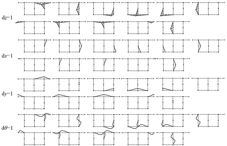
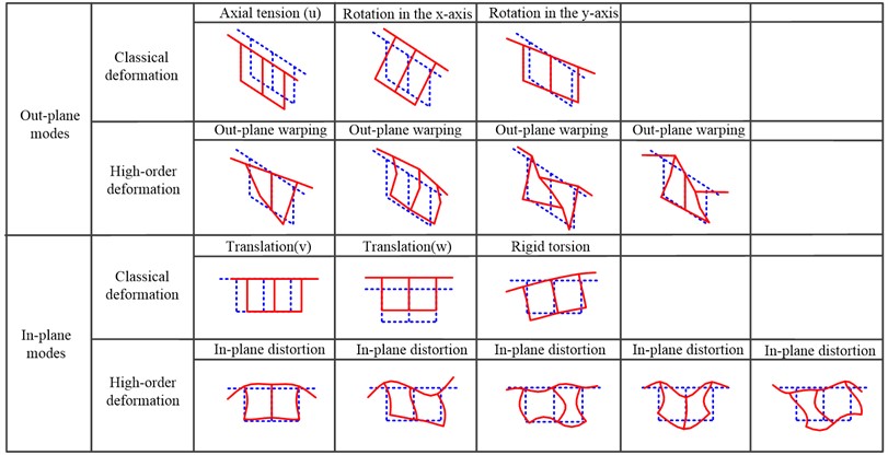
Under the premise of ensuring computational accuracy and reducing model complexity, high-order feature deformations with significant weights are used to reconstruct the initial high-order model. Since the classical deformation mode accounts for a large proportion of the first six modes, this paper directly selects modal vectors of the 7th-60th modes for pattern recognition. The fifteen sectional feature deformations were identified in Fig. 3. The first six modes are feature deformations in Timoshenko theory. The first three types of deformation outside the plane represent the axial extension, rotational displacement around the x-axis, and y-axis of the cross-section, respectively. The first three types of deformation in the plane represent the torsion of the cross-section and the translational displacement along the x-axis and y-axis. The nine feature deformations identified at the last represent the mechanical characteristics of the twin-cell box girder structure, such as warping and distortion. They represent high-order feature deformations introduced to improve computational accuracy.
Fig. 3Pattern recognition of in-plane and out-of-plane deformation modes
For the convenience of calculation, the one-dimensional high-order model and reconstructed model were both calculated using the finite element method, and eighty one-dimensional high-order elements were discretized axially by linear interpolation. Both ends of the twin-cell box girder were fixed, and then the natural frequency of the model was calculated. At the same time, a Shell 181 element model of twin-cell box girder was established in ANSYS software. The first fifteen natural frequencies were calculated through modal analysis.
In order to verify the accuracy of the one-dimensional high-order model considering cross-sectional deformation, the natural frequencies derived with the Timoshenko beam theory, the initial model, and the reconstructed model were compared with those of the ANSYS shell model. The results are shown in Table 1. The f1 is the solution of ANSYS shell element, and f2 is the result obtained from classical beam theory that only considers low order deformation. The f3 and f4 correspond to initial one-dimensional high-order models and the reconstructed one-dimensional high-order models herein, and u1, u2, and u3 represent the relative errors calculated based on the ANSYS shell model, respectively.
The relative error between Timoshenko beam theory and ANSYS shell element is relatively large after the second mode. Although it improves computational efficiency, the accuracy of the results is very low. The results of the initial high-order model is relatively more accurate, with relative error less than 2.42 % compared to the shell element.
The natural frequency of the initial high-order model is generally consistent with the results obtained by ANSYS software. The engineering calculation efficiency is improved while the accuracy is ensured. To further simplify the model and reconstruct the one-dimensional high-order model, the obtained natural frequencies are also well correlated with the shell element. The relative error of the first fifteen modes is controlled within 2.84 %, which greatly improves the accuracy compared to the traditional Timoshenko beam theory. This is due to the addition of four in-plane and five out-of-plane high-order feature deformations on top of the low order feature deformations. They weakens the stiffness of the twin-cell box girde, leading to a decrease in vibration frequency. The effectiveness and accuracy of higher-order elements have been verified through comparison. When engineering calculations are considered for second or higher order natural frequencies, it is evident that the deformation of higher-order cross-sectional features cannot be ignored.
Table 1The first fifteen natural frequencies and relative errors of the twin-cell box girder
Mode number | ANSYS | Timoshenko beam | Initial beam | Proposed beam | |||
f1 (Hz) | f2 (Hz) | u1 / % | f3 (Hz) | u2 / % | f4 (Hz) | u3 / % | |
1 | 8.9692 | 9.1964 | 2.53 | 8.7520 | –2.42 | 9.0650 | 1.07 |
2 | 12.746 | 13.423 | 5.31 | 12.485 | –2.05 | 12.916 | 1.33 |
3 | 16.292 | 22.224 | 36.41 | 16.146 | –0.9 | 16.541 | 1.53 |
4 | 21.141 | 25.194 | 19.17 | 21.028 | –0.53 | 21.736 | 2.81 |
5 | 23.876 | 30.782 | 28.92 | 23.523 | –1.48 | 23.982 | 0.45 |
6 | 24.209 | 38.362 | 58.46 | 24.017 | –0.79 | 24.273 | 0.27 |
7 | 26.802 | 42.155 | 57.28 | 26.381 | –1.57 | 26.59 | –0.79 |
8 | 28.271 | 46.813 | 65.59 | 27.905 | –1.29 | 29.073 | 2.84 |
9 | 32.744 | 51.369 | 56.88 | 32.326 | –1.28 | 32.713 | –0.09 |
10 | 33.383 | 56.214 | 68.39 | 33.055 | –0.98 | 33.287 | –0.29 |
11 | 33.422 | 60.71 | 81.65 | 33.329 | –0.28 | 33.952 | 1.59 |
12 | 36.371 | 73.449 | 101.94 | 35.522 | –2.33 | 35.849 | –1.44 |
13 | 37.328 | 75.114 | 101.23 | 36.698 | –1.69 | 37.166 | –0.43 |
14 | 38.104 | 79.819 | 109.48 | 37.357 | –1.96 | 37.542 | –1.48 |
15 | 38.374 | 93.639 | 144.02 | 37.755 | –1.61 | 38.046 | –0.85 |
4.2. Applicability verification
In order to further investigate the dynamic behavior of twin-cell box girders, a comparison is made between the 1st-9th vibration modes of the reconstructed one-dimensional high-order model and those of the ANSYS shell. The comparison was divided into nine pairs according to the order of the vibration modes, as shown in Fig. 4.
In each pair, the upper is derived using the reconstructed high-order model in Matlab software while the lower represents the ANSYS shell result. By comparing them, it can be observed that the good agreements between the reconstructed model and the ANSYS shell model. This indicated that the one-dimensional high-order model of twin-cell box girder, which took into account fifteen cross-sectional feature deformations, was able to accurately reproduce the three-dimensional dynamic behavior of the twin-cell box girder. At the same time, the identified in-plane and out-of-plane deformation modes were reflected in the vibration model, which strengthened the evidence linking deformation modes and structural behaviors. These findings further demonstrated the accuracy of the reconstructed high-order model.
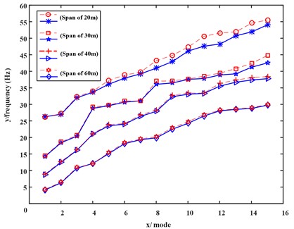
The slenderness ratio of thin-walled beams may affect the modeling accuracy. As shown in Fig. 5, twin-cell box girders with spans of 20 m, 30 m, 40 m, and 60 m are selected for analysis to investigate the dynamic characteristics of box girders with different spans. The blue lines represent the reconstructed model, and the red imply the results of the ANSYS shell.
The natural frequency of the box girder decreases continuously as the span increases. When the span of the box girder is 20 m, the overall span to width ratio of the box girder is 2.5, and the calculated relative error can also be controlled within 5.85 %. As the span of the box girder continues to increase, the relative error also decreases. It is worth mentioning that the reconstructed model achieves a high level of accuracy while utilizing only fifteen degrees of freedom. This significantly improves the computational efficiency. This suggests that the reconstructed model still exhibits a certain correlation with the shell model despite reducing the degrees of freedom of the initial model. The identified cross-sectional feature deformation is applicable to twin-cell box girder models with a span to width ratio of 2.5 or higher. The application scope is more broader than classical beam theory.
Fig. 4Comparison of vibration modes from reconstructed high-order model and ANSYS shell model
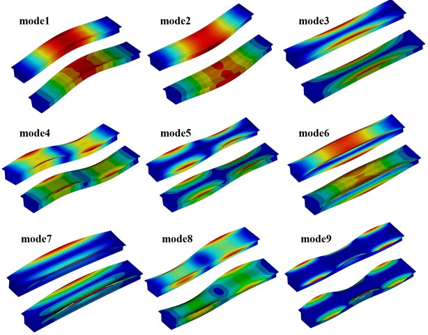
Fig. 5Comparison of the first fifteen frequencies between reconstructed model and ANSYS shell model
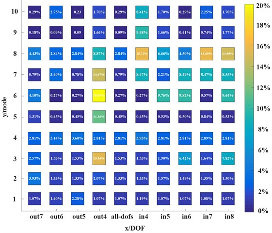
To further verify the effectiveness of higher-order deformations, the in-plane and out-of-plane high feature deformations were sequentially removed from the reconstructed higher-order model. The calculation results were shown in Fig. 6. The x-axis represents the one-dimensional higher-order model with fourteen degrees of freedom (remove in-plane or out-of-plane one in sequence), and the y-axis represents the1st-10th modes of the model. When the fourth out-of-plane warping higher-order deformation was removed, the natural frequency error solved by the model increased. Different results were obtained when other out-of-plane warping deformation results were removed. The fourth higher order warping deformation has a significant proportion of weight, while the latter three warping deformations have a smaller proportion of weight in the 1st-10th modes. It demonstrates the importance of accurately selecting significant cross-section deformations while ensuring accuracy requirements. When the cross-sectional deformation in the plane was removed, the frequency error changed greatly. It indicated that the weight of the selected in-plane cross-sectional deformation was relatively large in the calculation of the 1st-10th modes natural frequencies. This again demonstrated the accuracy and effectiveness of higher-order feature deformation.
Fig. 6Relative errors regarding natural frequencies with in-plane and out-of-plane feature deformations removed from the higher-order model in sequence
5. Conclusions
In this paper, a one-dimensional high order model of single-box twin-cell box girders was proposed with deformable cross-section. A set of shape functions was defined to capture cross-sectional deformation to construct the one-dimensional high-order initial model. The generalized eigenvalue problem of the governing equation was solved to uncouple the generalized displacements, and the combination of basis function weights were obtained involved with principal component analysis. In order to reduce the degree of freedom of the model and improve computational efficiency, a new shape function matrix was used to update the one-dimensional high-order initial model.
Numerical example analysis shows that the reconstructed one-dimensional high-order model can accurately describe the structural behavior of the twin-cell box girder. The calculated natural frequencies were much more accurate than classical beam theory and closer to two-dimensional shell elements. At the same time, the reconstructed one-dimensional high-order model had universal applicability to different constraint conditions and span to width ratios. It can also accurately reproduce 3D dynamic behaviours of the twin-cell box girder.
References
-
H. Cai and H. Lu, “Dynamic response of long-span continuous curved box girder bridge under seismic excitation,” Journal of Vibroengineering, Vol. 21, No. 3, pp. 696–709, May 2019, https://doi.org/10.21595/jve.2019.20345
-
Y. Wang, Y. Xu, Z. Luo, H. Wu, and L. Yan, “Spatial finite element analysis for dynamic response of curved thin-walled box girder bridges,” Mathematical Problems in Engineering, Vol. 2016, pp. 1–8, Jan. 2016, https://doi.org/10.1155/2016/8460130
-
L. Zhu, J.-J. Wang, M.-J. Li, C. Chen, and G.-M. Wang, “Finite beam element with 22 DOF for curved composite box girders considering torsion, distortion, and biaxial slip,” Archives of Civil and Mechanical Engineering, Vol. 20, No. 4, pp. 1–19, Sep. 2020, https://doi.org/10.1007/s43452-020-00098-y
-
C. Wang, Y. Zhang, X. Zhang, Y. Li, and X. Wei, “Coupled bending-torsion behaviour of single-box multi-cell curved composite box-girders with corrugated-steel-webs,” Journal of Constructional Steel Research, Vol. 196, p. 107411, Sep. 2022, https://doi.org/10.1016/j.jcsr.2022.107411
-
M. Luo, P.-Z. Lin, and L.-X. Sun, “Analysis of shear lag effect in twin-cell box girders,” in IOP Conference Series: Materials Science and Engineering, Vol. 563, No. 3, p. 032043, Jul. 2019, https://doi.org/10.1088/1757-899x/563/3/032043
-
J. Chithra, P. Nagarajan, and A. S. Sajith, “Investigations in twin-cell box girder bridges subjected to combined effects of bending and torsion,” Innovative Infrastructure Solutions, Vol. 7, No. 1, pp. 1–13, Dec. 2021, https://doi.org/10.1007/s41062-021-00719-2
-
A. Androus, H. M. Afefy, and K. Sennah, “Investigation of free vibration and ultimate behavior of composite twin-box girder bridges,” Journal of Constructional Steel Research, Vol. 130, pp. 177–192, Mar. 2017, https://doi.org/10.1016/j.jcsr.2016.12.017
-
Y.-J. Zhu, X. Nie, J.-J. Wang, M.-X. Tao, and J.-S. Fan, “Multi-index distortion control of steel-concrete composite tub-girders considering interior cross-frame deformation,” Engineering Structures, Vol. 210, p. 110291, May 2020, https://doi.org/10.1016/j.engstruct.2020.110291
-
X. Zhang, X. Yu, S. Du, J. Chen, and Y. Fu, “A box-girder bridge inspired by beetle elytra and the buckling and shear properties of a trabecular-honeycomb steel web,” Journal of Bridge Engineering, Vol. 27, No. 5, p. 04022, May 2022, https://doi.org/10.1061/(asce)be.1943-5592.0001855
-
X. He, Y. Xiang, X. Qiu, and Z. Chen, “Shear lag including axial balance of box beams by finite segment model,” Journal of Constructional Steel Research, Vol. 189, p. 107043, Feb. 2022, https://doi.org/10.1016/j.jcsr.2021.107043
-
C. Gao, L. Zhu, B. Han, Q.-C. Tang, and R. Su, “Dynamic analysis of a steel-concrete composite box-girder bridge-train coupling system considering slip, shear-lag and time-dependent effects,” Buildings, Vol. 12, No. 9, p. 1389, Sep. 2022, https://doi.org/10.3390/buildings12091389
-
P. Lu, D. Li, Y. Zhang, and Y. Zhou, “Bending characteristics of composite box girder considering all surfaces shear deformation based on Hamiltonian system,” Mechanics Based Design of Structures and Machines, Vol. 51, No. 5, pp. 2583–2606, May 2023, https://doi.org/10.1080/15397734.2021.1903919
-
S.-A. Sideris and C. Tsakmakis, “Consistent Euler – Bernoulli beam theories in statics for classical and explicit gradient elasticities,” Composite Structures, Vol. 282, p. 115026, Feb. 2022, https://doi.org/10.1016/j.compstruct.2021.115026
-
R. F. Vieira, F. B. E. Virtuoso, and E. B. R. Pereira, “Definition of warping modes within the context of a higher order thin-walled beam model,” Computers and Structures, Vol. 147, pp. 68–78, Jan. 2015, https://doi.org/10.1016/j.compstruc.2014.10.005
-
M. Epstein and R. Segev, “Vlasov’s beam paradigm and multivector Grassmann statics,” Mathematics and Mechanics of Solids, Vol. 24, No. 10, pp. 3167–3179, Mar. 2019, https://doi.org/10.1177/1081286519839182
-
S. Choi and Y. Y. Kim, “Higher-order Vlasov torsion theory for thin-walled box beams,” International Journal of Mechanical Sciences, Vol. 195, p. 106231, Apr. 2021, https://doi.org/10.1016/j.ijmecsci.2020.106231
-
W. Jrad, F. Mohri, G. Robin, E. M. Daya, and J. Al-Hajjar, “Analytical and finite element solutions of free and forced vibration of unrestrained and braced thin-walled beams,” Journal of Vibration and Control, Vol. 26, No. 5-6, pp. 255–276, Nov. 2019, https://doi.org/10.1177/1077546319878901
-
H. Kim and G. Jang, “Higher-order thin-walled beam analysis for axially varying generally shaped cross sections with straight cross-section edges,” Computers and Structures, Vol. 189, pp. 83–100, 2017, https://doi.org/10.1016/j.compstruc
-
M. Zhou, Y. Zhang, P. Lin, and Z. Zhang, “A new practical method for the flexural analysis of thin-walled symmetric cross-section box girders considering shear effect,” Thin-Walled Structures, Vol. 171, p. 108710, Feb. 2022, https://doi.org/10.1016/j.tws.2021.108710
-
L. Vieira, R. Gonçalves, D. Camotim, and J. O. Pedro, “Generalized Beam Theory deformation modes for steel-concrete composite bridge decks including shear connection flexibility,” Thin-Walled Structures, Vol. 169, p. 108408, Dec. 2021, https://doi.org/10.1016/j.tws.2021.108408
-
D. Henriques, R. Gonçalves, C. Sousa, and D. Camotim, “GBT-based time-dependent analysis of steel-concrete composite beams including shear lag and concrete cracking effects,” Thin-Walled Structures, Vol. 150, p. 106706, May 2020, https://doi.org/10.1016/j.tws.2020.106706
-
F. Cambronero-Barrientos, Aragón-Torre, J.-A. Martínez-Martínez, and G. Aragón-Torre, “Experimental verification of a beam element for thin-walled beams with torsion, distortion, and shear lag,” Engineering Structures, Vol. 261, p. 114249, Jun. 2022, https://doi.org/10.1016/j.engstruct.2022.114249
-
L. Zhang, W. Zhu, and A. Ji, “Application of pattern recognition to the identification of cross-section deformation modes of thin-walled structures,” IEEE Access, Vol. 7, pp. 169586–169598, Jan. 2019, https://doi.org/10.1109/access.2019.2954712
-
“Code for design of concrete structures,” (in Chinese), GB 50010-2010, 2010.
-
X.-X. Cheng, “Model updating for a continuous concrete girder bridge using data from construction monitoring,” Applied Sciences, Vol. 13, No. 6, p. 3422, Mar. 2023, https://doi.org/10.3390/app13063422
About this article

The authors gratefully acknowledge the financial support of National Natural Science Foundation of China (Grant No. 51805144), and Changzhou Sci and Tech Program (Grant No. CJ20220081 and CZ20190018).
The datasets generated during and/or analyzed during the current study are available from the corresponding author on reasonable request.
Yuhang Zhu was responsible for writing–original draft preparation and visualization. Lei Zhang was responsible for methodology and writing-review and editing. Tao Zeng was responsible for formal analysis and investigation.
The authors declare that they have no conflict of interest.
